
By RICHARD J. KAUFMAN
The folded dipole antenna is surely the most popular FM antenna there is, for almost every tuner and receiver ever made has been shipped with one. Surprisingly, every one of these antennas has an innate design flaw. This error in construction is easy to correct with only a soldering iron and a bit of wire.
A single half-wave length of wire, tapped at the center, is a dipole antenna (Fig. 1A). A dipole's impedance is approximately 75 ohms. Figure 1B shows a folded dipole antenna. It is made from two parallel wires, each one wavelength long, joined at the ends.
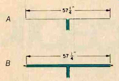
Fig. 1--A simple dipole antenna (A) and a typical folded dipole antenna (B) for
FM.
One of the wires is tapped in the center to feed the signal to a receiver by a transmission line. In theory, the folded dipole has greater bandwidth than the dipole.
In a folded dipole, two wires carry the same total current as the single wire in a dipole, but the current is di vided between them. Each wire has half the current, but the antenna delivers the same power to the receiver.
Since power is a function of the square of the current (P = R x I2), it follows that this results in a fourfold increase in the antenna's impedance. A folded di pole has an impedance of 300 ohms, which matches 300-ohm twin-lead antenna wire. It is very simple to build the whole antenna from twin-lead transmission line, and this is almost always done.
This doesn't give the intended results, however, because the speed of a radio wave in a transmission line is not the same as it is in free space. The presence of an insulator between the wires slows the radio wave, thereby making the line effectively longer than one-half wavelength.
To a radio wave in space, the folded dipole is the correct length, but to a radio wave flowing on the antenna, the folded dipole is also a transmission line--and too long. The result: Instead of feeding all their energy into the transmission line, radio waves bounce around in the antenna, interfering with reception in much the same manner as multipath reflections from buildings and mountains.
Correcting this innate mismatch between antenna length and transmission-line length is not difficult. Figure 2 shows the proper construction of a folded dipole antenna from 300-ohm twin-lead wire. The velocity factor of this kind of wire is 82%; thus, a quarter-wave length of transmission line is 82% of the length of a half wave in free space. The dimensions given in Fig. 2 are for 98 MHz, the center of the FM band, an acceptable compromise for general reception. However, if your interest lies at the high or low end of the FM band, you can scale the antenna for your needs. The formula for a half wavelength (in inches) is 5,616 divided by the frequency ( n megahertz).
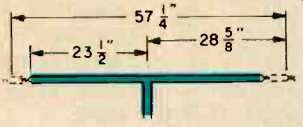
Fig. 2--Corrected twin-lead folded dipole antenna for FM.
Fixing Your Folded Dipole
If you already have a folded dipole antenna, modify it by shorting the wires on each arm, 23 1/2 inches from the center of the antenna. Carefully scrape the insulation off the wires with a sharp knife, and solder a piece of wire between them. Solder is necessary for a good connection; otherwise, you might introduce more noise and distortion than you are correcting.
How good is this antenna? I found it gave a noticeable improvement on stations that had been unlistenable because of noise. In the January 1983 issue of Audio, Len Feldman reviewed several outdoor FM antennas. As a point of reference, he measured a folded dipole antenna and found its standing-wave ratio to range between 2.5 and 1.5, depending on frequency. A perfect antenna would have a ratio of 1.0. In theory, measurements of a properly made dipole such as the one described here would be very close to 1.0 at the center of the FM band and would be much lower than 2.5 at the extremes.
Antenna Positioning
Even the best antenna will not work when it is improperly placed. A horizontal antenna should be at least half a wavelength above ground, or most of the signal will be lost. This is approximately 5 feet for FM. If your listening room is on ground level, you cannot simply place your antenna on the floor; on the second floor of a wood-frame house, putting the antenna under a rug will usually work. Be sure the transmission line to the receiver is at a right angle to the antenna for at least a quarter wavelength; a half wavelength is better, Note that if you live in a high rise building, floor placement of an antenna is rot a good idea. The floors of such buildings are made by pouring an inch or two of concrete into a metal pan; the pan is an effective ground. In such a building, the ceiling, is also a ground. Your best chance is probably with the antenna midway between floor and ceiling. Tacking the antenna to a wall is usually all right, but if there is metal in the wall, it could be a problem. Most houses have an aluminum vapor barrier on the exterior insulation. This, too, is a ground. Windows might work, but they often have screens.
To summarize: In a brick or wood-frame house, the best antenna position is probably on a second-story floor or an interior wall. In an older building with no vapor barrier, an exterior wall is probably best, while for a new high rise structure, an interior wall might be best. Putting the antenna outdoors, as on a balcony, will usually increase signal strength by several decibels, though outdoor placement is not al ways practical.
In any case, experiment with several locations for your antenna, and re member: It is not uncommon for a location that violates these rules to give the best reception in some unusual situations.
Collinear Antennas
If adding two small pieces of wire to a dipole antenna can improve FM reception, imagine what a better antenna design might do. Many different antennas can be fashioned from wire. The best of them offer such an improvement over the dipole that it is surprising they are not better known.
Figure 3 shows a collinear wire antenna. It consists of three half-wave sections, kept in phase with each other by half-wave phasing sections of transmission line. Lamp cord pulled apart into single wires can be used for the half-wave sections, and twin-lead wire for the phasing sections. The dimensions given for the phasing sections assume an 82% velocity factor, as found in standard 300-ohm twin-lead antenna wire. The dimensions in Fig. 3 are- for 98 MHz. Although you can scale the antenna for other frequencies, its bandwidth is even greater than the folded dipole so it is probably not worth changing the dimensions except in unusual situations. This antenna's impedance is slightly more than 300 ohms, so it can be used with 300-ohm transmission line with no difficulty. Another alternative is to place a balun transformer at the antenna's center and use coaxial cable to connect to a tuner's 75-ohm input. The gain of this antenna is 3.2 dB, so it delivers more than twice as much power as a dipole.
The pickup pattern is like a cylinder--running the length of the antenna, with nulls at the ends.
The length of this antenna is almost 10 feet, which can be awkward, especially in a small room. It is possible to bend the antenna at the center so that it forms a "V." The feed line can be run up the wall in a corner, with the antenna arms extending at right angles along the wall (although 15° is the theoretical optimum). Doing this eliminates the end nulls, increases the gain in the direction between the arms of the "V," and reduces gain in the opposite direction. Keeping the antenna basically straight, with only the last foot or two of each arm bent (up, down, or sideways) is another option.
If you want to try putting this antenna under a rug, keep the twin-lead phasing sections at right angles to the rest of the antenna. The feed line to the tuner should at right angles to the antenna, although departures from this ideal are not intolerable.

Fig. 3--Co/linear antenna.
The Sterba Curtain
Figure 4 shows another antenna, the Sterba curtain, named after its inventor, E. J. Sterba. This antenna has a little more than 6 dB of gain, which should be enough to satisfy anyone within 70 miles-or even more of a station. Like the three-section collinear antenna, it can be used with a 300-ohm feed line or with a balun and 75-ohm coaxial transmission line. The actual impedance is 400 ohms, which will not be a significant mismatch. The Sterba curtain's directionality is broad side to its plane. It cannot be used under a rug, unless the FM station you are seeking is on the moon or one of the nearer planets. The horizontal elements of the antenna can be bent in the center or symmetrically at the ends to eliminate the end nulls, as long as they remain horizontal. Do not bend the vertical elements.
Fig. 4--The Sterba curtain antenna.
FM radio enthusiasts who experience reception problems should consider alternative indoor antennas before spending the money and time to buy and install outdoor antennas. Better reception may simply require modifying or repositioning the folded dipole already in use--or, at most, constructing one of the simple antennas described here.
(adapted from Audio magazine, Jan. 1991)
= = = =