Manufacturer's Specifications
Circuit Design: Passive; dual mono, with separate volume controls and ground planes for each channel.
Grounding: Star grounding for hum and r.f. rejection; switchable connection to chassis ground.
Dimensions: 13 in. W x 3 1/2 in. H x 5 1/4 in. D (33 cm x 8.9 cm x 13.3 cm).
Weight: 9 1/2 lbs. (4.3 kg).
Price: $2,195.
Company Address: 833 Southwest Sunset Blvd., Suite L57, Renton, Wash. 98055.
Now here is a device after my own heart: A passive preamp/control center using switched attenuators. I have been using a similar unit, although one not nearly as carefully thought-out and crafted, for a number of years as my reference. I have reviewed various active preamps and line level stages over the years, and even though apparent detail and resolution have been improved over my passive reference in a number of cases, I have always preferred the overall musicality of my reference. Apparently, I am not the only person who thinks this way, as witness the component being reviewed here.
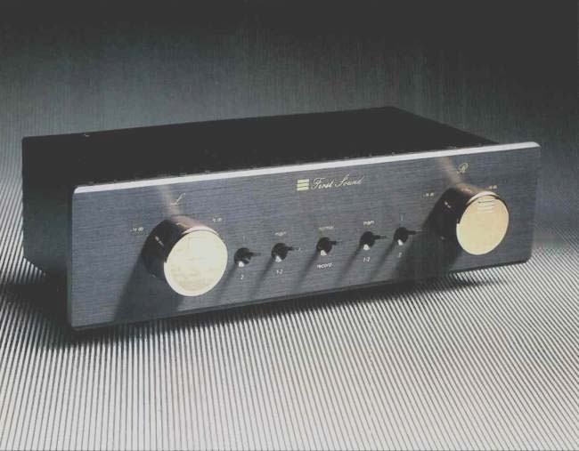
First Sound's Reference II (to shorten its formal title) functions like a standard preamplifier in providing input signal selection and control of volume and balance. Unlike a standard preamp, it doesn't have an active line-level stage for driving the cable to the power amp. Further, it does not have a phono preamp stage. The Reference II provides for three signal inputs and for two outputs, main and tape out.
For a simpler and purer signal path, there is no balance control per se, but rather two individual volume controls with big, gorgeous golden knobs. Balance is accomplished by setting the individual volume controls appropriately. This is a pain in the butt at first yet is fairly easy to get used to.
Other controls on the front panel are five toggle switches. The two outside switches select input "1" or "2," and the pair just inside of them switches between the "Main" input, muting, or the signal selected by the previous switch pair.
The switch in the center, "Normal/Record," enables or disables the tape output jacks. The input selector switches are separate for each channel, and the center switch is the only common physical point between the otherwise separated and shielded channels.
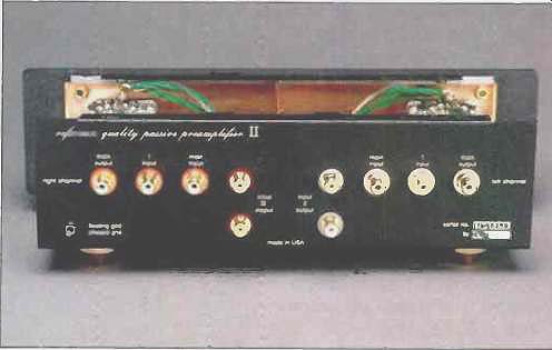
On the rear panel are the signal input/output connectors. Of these, the jacks for the "Main" signal input and output, and for input "1," on my sample were WBT phono connectors, while the jacks for input "2" and output "2" (tape) appeared to be Tiffany brand; current units, however, use Cardas jacks throughout. According to the manufacturer, the "Main" inputs are the purest or least "unhindered," so they should be used for your most favored source instead of input "1" or "2." A toggle switch on the lower right-hand corner connects or isolates the chassis ground and the grounds of both signal channels.
The Reference II's enclosure is made up of two U-shaped pieces. One piece is bent to form the front subpanel, bottom, and rear of the unit, while the other forms the top and sides. A '/4-inch-thick front panel completes the physical picture. The chassis is aluminum and lined with copper for maximum shielding against r.f. interference.
Circuit Description
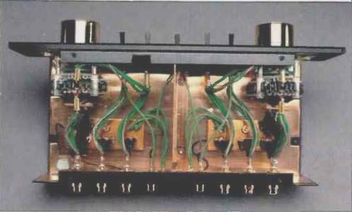
I can hear it now: Circuit description? How can he talk about a circuit without amplifying devices? Well, let me tell you, if manufacturers of active electronics paid as much attention to the passive circuitry of their products as was lavished on the Reference II, their products could sound considerably better. Of the many elements that make up the Reference II, I'll start with the selection of the volume-control attenuators. These are Shallcross step rotary switches that comply with MIL-S3786/40 Standard and are specifically designed to endure vibration and both physical and thermal shock. These switches have a contact rating of 10 amperes continuous at 115 V-most likely the highest contact rating ever used in the hi-fi industry for an attenuator. Solid silver alloy contacts are used in both the fixed and movable parts of the switch; the movable parts are double-leaf wiper arms.
This means that there is no plating to wear off, giving consistent contact quality over the life of the switch. These switches are really superior and quite costly. (I can attest to their high price, for I use a similar Shallcross switch in my own reference signal selector/switched attenuator. A number of years ago, I bought several switches for, I believe, $40 to $50 each.) The topology of the attenuator circuit is interesting and unusual. Instead of being a tapped voltage divider with as many resistors as attenuation positions, all in series, the attenuator is a ladder type that switches in individual pairs of resistors for each position. (I must say I also use this topology in my own reference unit, an idea originated not by me but by an associate, Tom Baldwin.) Two resistors in a circuit at a time is logically better than, say, 30 resistors, and the mechanical and solder connections to wire them, all in series. These resistors are made by Holco and use no steel or ferrous material in their construction. According to First Sound, they are superior to the "industry standard" Roden stein Resista units. The 20-gauge copper leads of the wires are looped twice through the solder lugs of the switch contacts to ensure mechanical contact integrity before soldering. In addition, WBT crimping sleeves are used on the toggle switches and the attenuator input and output joints to further ensure a stable positive mechanical contact for the joints. Copper solder is then applied to these joints.
A variety of Cardas Cable is used for the internal wiring. Each interconnection uses a number of these wires, some as large as 6-gauge, in parallel. First Sound felt that this wire's design, which is said to minimize internal signal induced vibration, was a factor in minimizing sonic degradation. The internal wiring topology, developed after much listening, includes such interesting touches as orienting the direction of each internal cable for best sound. Two types of solder are used for the various internal joints, a special copper type and Wonder solder.
First Sound makes a point in their technical description of paying as much attention to the ground side of the circuit as to the hot side. The signal common leads can be connected to the chassis, or isolated from it, by setting a rear-panel switch; the designers say that isolated operation is preferred, perhaps for better rejection of external fields, but that grounded operation may yield lower hum in some installations. The common point for all of the ground connections in each channel is a large, thick ground-bus plate, made of oxygen-free copper, at the bottom of the enclosure. These plates are electrically isolated from the chassis by insulated standoffs and are connected to each circuit point by a number of individual Cardas wires in parallel.
The descriptive literature for the Reference II states that just the right kind and amount of vibration damping has been applied, again determined by listening tests. Unwanted vibrations are handled by special damping material applied wherever First Sound considered it appropriate.
The feet of the unit are cone-shaped, mounted to the bottom of the chassis with large bolts but isolated with Navcom damping material.
The owner's manual and other descriptive literature supplied with the Reference II were very informative and make a good case for the techniques used in the unit's construction.
Measurements
Again, I can hear the muttering out there: What's to measure on something with no amplifying devices? One very measurable thing is the Reference II's effect on frequency response delivered to the power amplifier as a function of interconnect cable capacitance and volume control position. I also thought it would be interesting to see if the great resolution of my Audio Precision test gear could reveal any distortion added by this passive circuitry.
Figure 1 shows the effect on frequency and phase response of the Reference II, with two different loads, as a function of attenuation. In both figures, the knob positions used to produce the curves are the same except that an extra curve, for position 10, has been added to Fig. 1B. In Fig. 1A, the total capacitance is on the order of 400 pF, which includes my measurement cables plus the input capacitance of the Audio Precision analyzer. For Fig. 1B, the IHF load has been added. The effect of this load's extra capacitance in reducing high-frequency response is somewhat diminished by the load's 10 kilohms of resistance, which helps to lower the attenuator's effective series resistance at its highest output resistance points.
The curves in Fig. 1A show pretty reasonable high-frequency response and are more or less representative of what you would get with a pair of 1-meter interconnects used between the Reference II and a power amplifier. The response in Fig. 1B is obviously worse but, as a point of reference, is better than that of any CD player. (Note that the frequency scale here ends at 200 kHz.) In my opinion, this is a small price to pay for the otherwise superior sound possible with a passive preamp like the Reference II. Total harmonic distortion plus noise was measured as-a function of frequency at full volume and at approximately 6 dB down, using an input level of 10 V rms (Fig. 2). The plot is essentially that of the System One's residual noise level, as the results looked the same when not going through the Reference II. The top curve, for an attenuation setting of approximately -6 dB, appears to show more distortion because the relative input S/N ratio of the System One is not as good with the input level reduced.
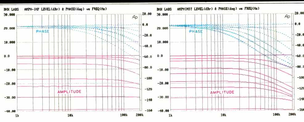
Fig. 1A--Phase and frequency response for volume settings
from 0 to 28, for instrument loading; see text. Frequency response curves,
from top to bottom, are for volume settings of 0, -1, -2, 6, -17, -22,
-25, and -28. Phase response curves, from top to bottom, are for settings
of 0, -28, -25, -1 and -22, -2 and -17, and -6. Fig. 1B--Same
as Fig. 1A but for IHF loading. Frequency response curves, from top to
bottom, are for volume settings of 0, -1, -2, 6, -10, -17, -22, 25, and
-28. Attenuation settings for phase response curves are same as for Fig.
1A except that bottom curve is for both -6 and -10.
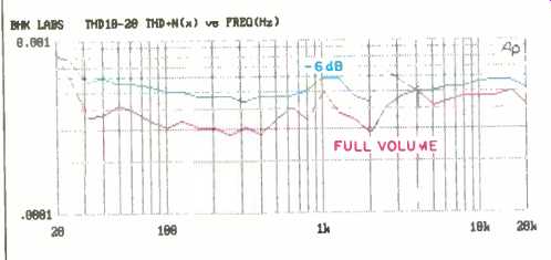
Fig. 2--THD + N vs. frequency, for attenuation settings of 0 (full volume)
and -6; see text.
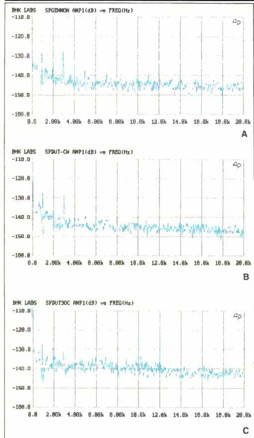
Fig. 3--Distortion spectra for test system generator output (A), Reference
II with volume control at maximum (B), and Reference II with volume control
at -6 (C). See text.
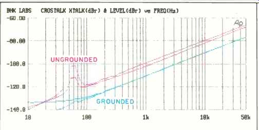
Fig. 4--Crosstalk vs. frequency, at full volume setting, with signal commons
grounded to chassis and ungrounded.
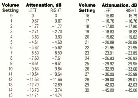
Table I--Volume-control attenuation and tracking vs. position, with instrument
load.
Next, a series of spectra was taken using a 1-kHz frequency and, again, a 10-V input. Figure 3A, the output of the Audio Precision System One's generator, is provided for reference. Figure 3B is the output of the Reference II with the volume fully clockwise. As can be seen, the distortion spectra of Figs. 3A and 3B are essentially identical regarding the amplitudes of the second and third hamonics, the only significant distortion products. In Fig. 3C, the volume is reduced about 6 dB. The noise level is higher, as in Fig. 2, and the second and third harmonics' amplitudes are different than in Figs. 3A and 3B. This difference may or may not be from the Reference II; it could be the System One's behavior with a 5-kilohm source. In any case, it's important to note that we're talking about one part per million here!
Crosstalk as a function of frequency is plotted in Fig. 4. The curves showing greater crosstalk, and a bit of 60-Hz hum, are with the chassis enclosure not grounded to signal common; the lower curves are with the chassis grounded to signal common. The performance here is quite good. Further, and this is not usual, the crosstalk shown for 0-dB attenuation with the enclosure grounded did not increase when the controls were set at about -6 dB. Table I shows both channels' tracking and actual attenuation values with a 100-kilohm load. Maximum tracking error is 0.03 dB. Is this accurate or what?!
Use and Listening Tests
Signal sources used to review the First Sound Reference II included an Oracle turntable fitted with a Well Tempered Arm and Spectral Audio MCR-1 Select cartridge fed to the Reference II through a Vendetta Research SCP-2B phono preamp. Magnavox's CDB-560 CD player, used as a transport, and Krell's MD-1 CD transport were paired with both Wadia 2000 and Krell SBP-64X decoding units. The remaining program sources were a Nakamichi 250 cassette recorder, a Technics 1500 open-reel recorder, and a Nakamichi ST-7 tuner. I hooked up and used the Reference II just as I do my own signal selector and switched attenuator unit-or any active preamplifier, for that matter. High-level sources, including the output of the Vendetta Research phono preamp, were connected to the inputs; the outputs drove the interconnect cables that went to the power amplifiers. These power amplifiers included a pair of Carver Silver Sevens, a pair of Luxman MB3045s modified to use EL-34 output tubes, a Jetf Rowland Model 1, a McIntosh MC2600, and a prototype 50-watt/channel switching amplifier designed by a friend of mine. Speakers used were the Spica Angelus, the Martin-Logan Monolith Ill, and an experimental pair of two-way systems that were loaned to me by Arnold Nudell.
When I first received the Reference II, I immediately put it in my system. First impressions were that it sounded just about like my own reference signal selector/switched attenuator. I then loaned it to a friend who has a great-sounding system consisting of a pair of Apogee Divas driven with EAR 549 200-watt tube amps. This friend has a phono preamp like my reference tube preamp and a signal selector/ switched attenuator like my own but with different kinds of attenuator and signal-selector switches. After using the Reference II for a while, he thought that it sounded about like his normal unit.
After measuring the Reference II, I set it back up in my system. Again, I thought it sounded about like my own unit but with a trace more openness due, perhaps in part, to its higher cutoff frequency when driving my interconnect cable.
I think the Reference II sounds absolutely outstanding and takes the passive preamp/control approach about as far as I can reasonably think of its going. There are some engineers who think driving an interconnect to the power amp with a passive volume control is just not right. They correctly cite variable frequency response (demonstrated by the figures here) and claim that you can't have high fidelity with a cutoff frequency that is so low and variable. I have heard good sounding line sections with low output impedance that bring a bit more detail and resolution to the music, but I generally have been happier with a setup using something like the Reference II. However, I am going to research this situation further with a tube preamp I recently heard that has the above-mentioned effect on the reproduction.
When I used the Reference II, the only objection I could think of was that the knobs are a bit hard to turn. I would have opted for softer switch detents for easier turning. The manual does say that the knobs will loosen up with use, although I haven't seen much change so far. The piece is somewhat front-heavy when not hooked up, but that works in favor of its not tipping backwards when the cable load weights it down from the rear.
In conclusion, I think that First Sound's Reference II is about as good as a passive volume-control system gets. If the prospective purchaser's tastes are at all similar to my hopefully clear biases, I would enthusiastically recommend this unit.
-Bascom H. King
(Source: Audio magazine, Jan. 1992)
Also see:
Kinergetics KPA-1 Preamp (Aug. 1986)
= = = =