Manufacturer's Specifications:
FM Tuner Section Usable Sensitivity: Mono, 10.8 dBf.
Fifty-dB Quieting Sensitivity: Mono, 16.2 dBf; stereo, 37.7 dBf.
S/N: Mono, 93 dB at 80 dBf; stereo, 86 dB at 80 dBf.
THD at 80 dBf: Wide-mono, 0.0095% at 100 Hz and 1 kHz; 0.01% at 10 kHz; stereo, 0.02% at 100 Hz and 1 kHz; 0.07% at 10 kHz; narrow-mono, 0.09% at 1 kHz; stereo, 0.5% at 1 kHz.
Frequency Response: 20 Hz to 15 kHz, +0,2 dB,-0.8 dB.
Stereo Separation: Wide -65 dB at 1 kHz, 50 dB, 20 Hz to 10 kHz; narrow -40 dB, 20 Hz to 10 kHz.
Capture Ratio: 0.8 dB (wide). Selectivity: 85 dB (narrow).
Muting Threshold: 25.2 dBf.
Audio Output Level: 650 mV at 100% modulation.
AM Tuner Section Sensitivity: 150 µV/meter.
S/N: 50 dB.
Audio Output Level: 150 mV at 30% modulation.
General Specifications
Power Requirements: 120 V a.c., 60 Hz, 14 watts.
Dimensions: 16-9/16 in. (42 cm) W x 2 3/8 in. (6.1 cm) H x 12 1/2 in. (31.7 cm) D.
Weight: 9 lbs., 15 oz. (4.5 kg).
Price: $300.00.
Company Address: P.O. Box 1720, Long Beach, Cal. 90801.
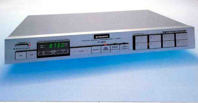
The most outstanding feature of this new AM/FM tuner from Pioneer is its Digital Direct Decoder, a unique system which decodes stereo directly from FM i.f. signals instead of having to decode the composite signal appearing at the output of the FM ratio detector or discriminator. The new circuit is said to improve overall sound quality of FM reception, particularly in the areas of stereo separation, distortion and signal-to-noise ratio.
Other features of the F-90 include "Auto Search," an electronic tuning circuit that searches for stations automatically, and preset selection for eight FM and eight AM stations. Narrow- or wide-band i.f. is selectable at the touch of a front panel button, too, so that listeners in differing r.f. environments (with many stations crowded together on the dial or with few stations widely separated in frequency) can select the optimum setting for best, interference-free reception. There's even a record-level check signal built into this tuner, which delivers a mid-frequency signal corresponding to about 50% modulation (of an FM signal) to help you set up tape recorder levels before beginning to record from FM. Control Layout A power on/off switch, its associated indicator light, and AM and FM band touch-button selectors are all located at the left end of this tuner's slim front panel. A multi-function display area just to the right of these pushbuttons shows tuned-to frequency (kHz for AM, MHz for FM), optimum tuning, reception of a stereo signal, and activation of the nearby "Memory" switch to store favorite AM or FM station frequencies. An up and down tuning switch, to the right of the display, is used for manual tuning; depressing the right half of the button moves frequencies upward, while touching the left half of the switch lowers frequencies. This tuning switch is also used for "Auto Search" -- touching it initiates the search action, which stops only when an acceptable signal has been tuned in.
The "Memory" switch comes next. It is followed by "Rec Level Check," "Manual Search/Mute-Off" and "FM IF-Band" switches, each with its own indicator light, and followed in turn by eight numbered "Station Call" buttons. By depressing any of these buttons, as many as eight AM and eight FM stations which have been previously stored can be recalled.
The "Manual Search/Mute-Off" switch is rather unusual in its operation. Though used primarily to choose between manual tuning and "Auto Search," it also turns interstation muting on and off. When FM muting is off (that's the same as when the switch is in the manual position), only mono transmissions can be received.
The rear panel of the F-90 is equipped with the usual AM and FM external antenna terminals. A true loop antenna (as opposed to the usual ferrite loopstick) is provided for AM reception. FM input connections include both a 75-ohm coaxial F-type connector and a 300-ohm twin lead. A slide switch determines AM channel spacing for the frequency synthesized tuning system (10-kHz spacing is used in the U.S., 9 kHz in other parts of the world). In addition to the usual left- and right-channel outputs, the tuner has an AM stereo output jack intended for connection to future AM stereo adaptors, if such products ever become available.
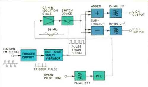
Fig. 1--Block diagram of Digital Direct Decoder.
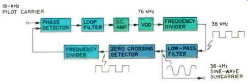
Fig. 2--Block diagram of phase-lock loop circuit used in the Digital Direct
Decoder.
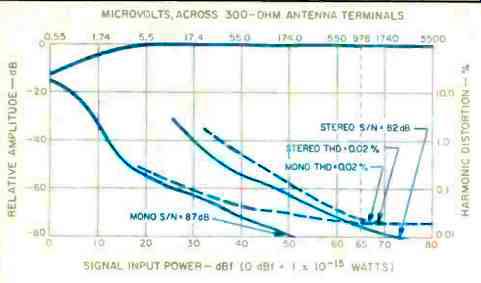
Fig. 3--Mono and stereo FM quieting and distortion characteristics, wide-band
i.f. mode.
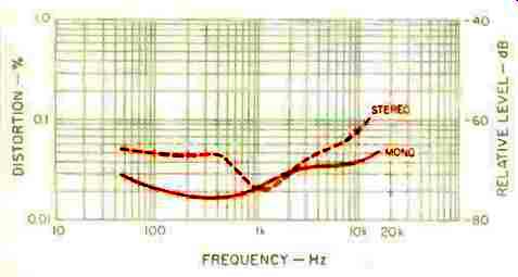
Fig. 4--Harmonic distortion vs. frequency, wide-band mode.
Digital Direct Decoder Circuit
In conventional FM tuners, the incoming radio frequency signal (at a frequency between 88.0 and 108 MHz) is converted to a 10.7-MHz intermediate frequency signal which is amplified and then demodulated by one of several available types of FM detectors. The composite signal recovered is then applied to a multiplex decoder circuit. This MPX decoder circuit usually re-creates a 38-kHz subcarrier by means of a phase-lock loop circuit. The composite stereo signal is then decoded by switching to produce separate left and right signals. In this conventional approach, it can be shown mathematically that certain undesired components appear in the decoded outputs. These cause a type of "beat" or interference generally referred to as "birdie" noise.
Most manufacturers attempt to counteract this problem by introducing filters between the output of the FM detector and the input to the stereo decoder circuitry. Such filters, however, introduce amplitude response irregularities as well as finite time delays. These filter imperfections, in turn, cause decreased separation at high frequencies. While it can be argued that separation need not be very great for frequencies above 8 or 10 kHz, distortion also rises rather rapidly when high-frequency audio is present in the trans mitted signals. Often, this distortion is in the form of lower frequency, audible "beats" or "birdies" rather than the more tolerable, pure harmonic distortion. Filters, in other words, can reintroduce the problem they're designed to prevent.
A block diagram of the direct stereo decoder is shown in Fig. 1. The 10.7-Mhz i.f. signal is first converted to 1.26 MHz.
A trigger circuit detects the zero-crossing point of the FM signal and generates a trigger pulse each time the axis crossing takes place. The trigger pulse, in turn, is used to fire a one-shot multi-vibrator which generates a constant width pulse train. So far, the description sounds a bit like that of a pulse-count detector (used by Kenwood and others in some of their FM products), but it is at this point that the major difference between pulse-count detectors and Pioneer's new Digital Direct Decoder occurs. In a conventional pulse-count detector, audio signals would now be reproduced by integrating the pulse train. In Pioneer's circuit, the pulse train is not directly integrated to form audio signals. It is first used as a control signal for a switch which "chops" a 38-kHz subcarrier sine wave, switching it on and off in sync with the pulses (which are variably spaced, as a function of the audio modulation in the original i.f. signal). This process effectively modulates the subcarrier with the audio information carried by the pulse train.
Adding this chop-modulated subcarrier and the original pulse train produces a left-channel signal; subtracting them produces a right-channel one. Because these signals were formed by combining squared-off pulse and sine-wave signals, they contain many undesired high harmonics, which are then filtered off by 15-kHz low-pass filters.
In examining the frequency spectrum generated by the pulse train and all the other signal components, composite signals are found in the low-frequency region; spurious signals exist at around 100 kHz, with the rest of the spectrum centered around 1.26 MHz and its harmonics. Because the pulse train is multiplied by the sinusoidal 38-kHz subcarrier, the spectrum around 1.26 MHz, with its harmonics and spurious signals, does not affect the audio signals, and beat noise is not generated. As a result, no amplitude or phase-altering filters need be inserted in the signal paths, and the measured separation remains extremely high even at the upper frequencies.
Since a sinusoidal subcarrier needs to be used in the new decoder (as opposed to a rectangular, switching waveform), the PLL circuitry needed to generate that subcarrier differs somewhat from the conventional phase-lock loop arrangement. A block diagram of this new type of PLL is shown in Fig. 2. The output frequency of the voltage-controlled oscillator is 76 kHz. This output is divided down to 38 kHz by a frequency divider. A band-pass filter converts the rectangular wave to a sinusoidal waveshape. The sine wave is again converted to a rectangular wave by a zero-crossing detector and is divided down to 19 kHz. The phase difference between the 19-kHz signal and the incoming pilot carrier in the pulse train is detected at the phase detector.
The phase-lock loop is completed by feeding the output of the phase detector through the loop filter and d.c. amplifier to the VCO. Any possible deterioration of separation due to phase error is eliminated, since any drift in the band-pass filter of the PLL .s corrected by this feedback loop.
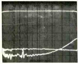
Fig. 5--FM frequency response (upper trace) and stereo separation (lower traces).
Note unusually uniform crosstalk in wide band mode, and increasing crosstalk
with rising frequency in narrow-band mode.
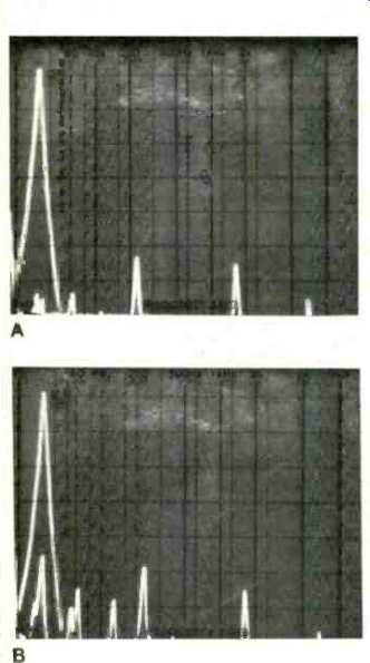
Fig. 6--Analysis of 5-kHz distortion and crosstalk for wide-band (A) and narrow-band
(B) i.f. settings.
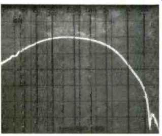
Fig. 7--AM frequency response.
Measurements
As so often happens with tuners that I am asked to test for Audio, the usable sensitivity of the F-90 sample I received was not quite as good as claimed by the manufacturer. I measured a mono usable sensitivity of 15.0 dBf (3.1 µV across 300 ohms), as opposed to 10.8 dBf claimed. Some of the discrepancy may be due to the matching transformer which I had to use between the output of my generator and the antenna terminals of the tuner. In any event, of far greater importance than usable sensitivity is 50-dB quieting, and here the tuner did very well indeed, reaching 50 dB of quieting with an input signal of only 16 dBf (3.5 µV across 300 ohms) in mono and 36 dBf (34.7 µV across 300 ohms) in stereo.
Even my Sound Technology FM generator is unable to confirm FM signal-to-noise ratios above 90 dB, as claimed (for mono) by Pioneer for this tuner, but I was able to obtain incredibly high S/N readings of 87 dB in mono and 82 dB in stereo--as high as I've ever read for any tuner. Harmonic distortion was a very low 0.02% in both mono and stereo (again, the readings may have been at the limit of my test equipment) when the "IF-Band" switch was set to the wide position. As I expected, when the narrow i.f. setting is selected, distortion rises somewhat, to 0.1% in mono and 0.15% in stereo, even at 1 kHz. Noise and distortion at 1 kHz are plotted as a function of input-signal strength in Fig. 3 for the wide setting. Very little difference in signal-to-noise performance was observed when switching to the narrow i.f. position; the chief differences observed were in selectivity, distortion, and high-frequency separation.
A significant benefit directly attributable to Pioneer's Direct Digital Decoder circuit is obvious from an examination of Fig. 4. Here, I have plotted distortion versus frequency, in mono and stereo, for the wide i.f. mode. Conventional tuners normally exhibit a steep rise in distortion at the high-frequency end of the spectrum when operating in the stereo mode. In the case of the F-90, harmonic distortion remained extremely low, measuring only 0.08% at 10 kHz.
Figure 5 is a spectrum-analyzer plot of frequency response and separation for the tuner. Response was flat from 20 Hz to 15 kHz, within 0.3 dB-even better than claimed by the manufacturer. The two lower curves of Fig. 5 are extremely interesting. The flatter, upper curve of these two is the crosstalk-plus-noise observed at the output of the un-modulated channel, in the wide-i.f. stereo mode. Separation remained well above 50 dB across the entire audio spectrum. While separation seems to be a bit higher in the narrow setting of the "IF-Band" switch for low and mid frequencies, it decreases rapidly at the high end, actually crossing the plot taken for the wide i.f. setting. This is the first time I have ever run into such a condition in tuners featuring wide and narrow i.f. settings. It is also the first time in my recollection that I have encountered a separation characteristic (in the wide setting) so uniform in its low crosstalk from one end of the spectrum to the other. Clearly, this, too, must be a direct result of the new multiplex decoder circuit pioneered by Pioneer (sorry about that!). I twice measured crosstalk and distortion components for a 5-kHz modulation, once for the wide i.f. setting and again for the narrow mode. Results are pictured in Figs. 6A and 6B. Notice how much lower in amplitude the crosstalk and distortion components are (all "blips" within and to the right of the tall, "desired output" blip at the left) in Fig. 6A (wide i.f.) compared with those shown in Fig. 6B (narrow i.f.). While I could not quite get a measurement of 0.8 dB for capture ratio (this is a tricky measurement to make, especially when results are such low numbers), I did manage to read 1.0 dB for this important characteristic. Alternate-channel selectivity measured exactly 85 dB, as claimed, for the narrow i.f. setting, decreasing to around 50 dB in the wide setting. Image, i.f., and spurious rejection, though not specified by Pioneer, were all safely above 90 dB, and I had no problems with such interference either during my bench tests or in subsequent listening tests.
As impressed as I was with the FM performance of this tuner, I was equally unimpressed with its AM section. The AM frequency response, plotted in the spectrum analysis 'scope photo of Fig. 7, tells about as much as one needs to know concerning this minimal AM section. Still, the F-90 is an excellent value--even if you never switch to AM; just think of it as a fine FM-only tuner.
Use and Listening Tests
I never cease to be amazed at what has happened to FM tuner technology in the past decade. Tuners costing five and 10 times as much as this one in the 1970s couldn't do as welt. The only fair way to do a listening test with a tuner such as this is to create a pure, "closed-circuit" signal, using digital program-source material fed directly to the modulation inputs of an FM generator, with the generator's output connected directly to the antenna terminals of the tuner. Under these closed-circuit conditions, it became possible to differentiate between the performance of the F-90 and the tuner that I keep as a "reference" (and which originally sold for around $500). The Pioneer won out in terms of clarity, low noise, and openness of sound. Only one station in my area comes close to duplicating these closed-circuit conditions, and when that station broadcasts CDs (as it occasionally does), I am also able to appreciate the superior performance of the Pioneer F-90. Clearly, it's a tuner ideally suited to the digital audio era that is upon us--at least until authorities in Washington provide us with a new FM service truly up to the task of handling the new digital program sources (if that ever happens).
-Leonard Feldman
=================
(Source: Audio magazine, Jan. 1984)
Also see: Pioneer Model TVX-9500 TV Audio Tuner (Nov. 1978)
Pioneer TX-9500-II AM/FM Stereo Tuner (May 1977)
= = = =