MANUFACTURER'S SPECIFICATIONS
Power Output: 65 + 65 watts at 8 ohms, 70 + 70 watts at 4 ohms, for 0.1% THD.
Power Bandwidth (IHF): 7 to 30,000 Hz.
Sensitivity: Phono, 1.2 mV; AUX, Tuner, Tape, 130 mV.
Signal/Noise: Phono, 70 dB; Others, 90 dB (weighted).
Frequency Response: 10 to 100,000 Hz +0,-2 dB.
Filters: Low, 6 dB/octave below 100 Hz; High, 6 dB/octave above 7,000 Hz.
Tone Controls: Bass, 100 Hz ± 10 dB; Treble, 10,000 Hz ± 10 dB; in ten 2 dB steps.
Dimensions: 15 3/4 in. W. by 12 7/8 in. D. by 5 7/8 in. H.
Price: $371.50 (plus applicable surcharge), wooden case: $24.50.
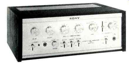
The Sony 1130 is an excellent example of the progress made in amplifier design over the past few years. It is quite small in size and not that expensive either, but the specifications were barely approached by top quality, highly expensive units only a short while ago. It has ample power for most purposes, distortion is almost immeasurable below its rated output, and just take a look at the facilities: Switched Low and HIGH filters, two PHONO inputs (useful for comparisons), provision for using the main amplifier or the preamplifier independently, auxiliary input sockets on the front panel, speaker switch, stereo mode selector, tape monitor level switch, and so on.
Step-type tone controls are used-these are a little expensive, but many people prefer the positive, repeatable action to the smoother control of the continuously variable kind. Certainly they stand up to hard use better-as a rule! The power switch is a separate lever type, and there are three outlet sockets on the rear panel, two of which are switched. Also at the rear are slide switches to disconnect the preamplifier from the power amp-nice for wiring in an equalizer or quadraphonic matrixer. Figure 1 shows the view inside-note the large power transformer and the big capacitors.
Circuit Details
The preamp section uses eight transistors per channel, four being FETs. Three of these are used for the feedback tone control stages, and one is at the input. Three silicon types are used in a muting circuit which effectively shorts the preamplifier output to ground for a short period after switching on. Thus any switching transients are prevented from reaching the loudspeaker. The main amplifier uses a differential input stage, an NPN-PNP complementary driver arrangement feeding the NPN output transistors. A dual positive-negative power supply is employed, thus the loudspeaker is directly connected without a capacitor. A total of 11 transistors are used for each channel, plus a number of diodes which are employed in protection circuits. Six more transistors are used in the regulated power supply and a protection circuit. There are actually two kinds of protection-one for the power transistors and the other for the loudspeakers. A short circuit at the speaker terminals will limit the input signal applied to the output transistors by means of a fairly conventional type of trigger circuit. The speaker protection circuit is similar to the one used on the larger TA-320OF (reviewed November, 1970) and is shown in Fig. 3. The output signal is take from the output terminal through a low-pass filter (R140 or R240, C313 and C314) and fed to a bridge rectifier (D307 through D310). Because of this filter, the only voltage applied to the bridge rectifier is the very low-frequency or d.c. component that might be caused by transistor faults. When this d.c. rectified voltage becomes large enough, it starts the Hartley oscillator (Q303 and Tosc). The oscillator output is rectified by D311 and thus provides trigger voltage for the SCR--D-317 when trigger voltage is applied to the gate of the SCR, the SCR turns on and shorts the base voltage to ground through D312, the SCR, and D315. The base voltage of the other driver transistor is also shorted to ground through D313, the SCR, and D314, stopping any current flow in the output stage and thus protecting the speaker system. Quite a complex arrangement-unusual in a unit in this price range!
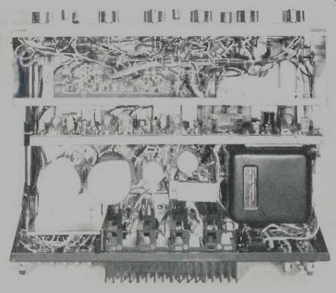
Fig. 1--Inside view.
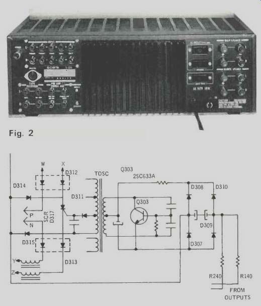
Fig. 2--Rear panel; Fig. 3--Partial schematic of speaker protection system. w,
x, Y, and z go to the driver transistor bases, P and N are connected to a power
limited or clamping circuit.
Performance Measurements
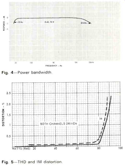
Fig. 4--Power bandwidth. Fig. 5-THD and IM
distortion.
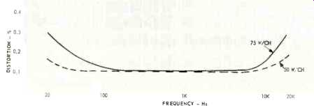
Fig. 6--Harmonic distortion versus frequency.
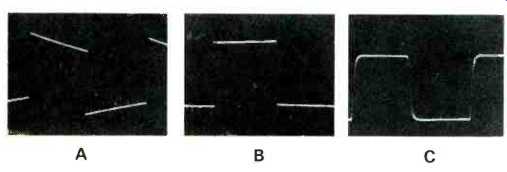
Fig. 7--Square wave response at A, 40 Hz; B, 1000 Hz, and C, 20,000 Hz.
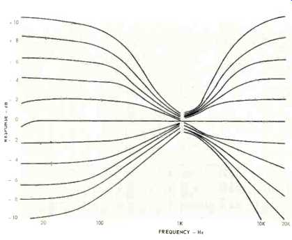
Fig. 8--Tone control curves.
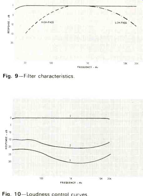
Fig. 9--Filter characteristics.
Fig. 10--Loudness control curves.
Power bandwidth curves are shown in Fig. 4, and it will be seen that half-power points are 17 Hz and just over 50,000 Hz--very creditable. Figure 5 shows the THD and IM characteristics. Rated output is given as 65 watts per channel into 8 ohms, but this was found to be a conservative figure. With both channels driven, we measured more than 80 watts per channel at the rated THD and over 90 healthy watts at the clip point. Perhaps more importantly, power was well maintained throughout the band, as can be seen from Fig. 6. In theory, the absence of a coupling capacitor improves the damping factor and this was found to be about 120 from 10 to 5,000 Hz, falling to 85 at 10,000 Hz. Phono sensitivity came out at 1.1 mV for full output and overload point was 86 mV. Input signal for the TUNER and Aux inputs was 160 mV. Signal/noise (unweighted, inputs terminated) was 66 dB for PHONO inputs and 86 dB for the others (referred to 80 watts). Residual noise, i.e. with the volume control at minimum, measured -87 dB. Crosstalk was -52 dB at 1000 Hz and -43 dB at 10,000 Hz. Frequency response, measured from the TUNER input, was 1 dB down at 10 Hz and 100,000 Hz. Figure 7 shows the excellent square-wave response at 40, 1000, and 20,000 Hz. Stability was checked with an electrostatic speaker load and was found to be completely satisfactory. Tone control response is shown in Fig. 8, high and low filters in Fig. 9, and loudness control in Fig. 10.
Listening Tests
How did the 1130 perform? Well, of course power output was ample for low efficiency speakers like the AR-3a or B&W 70, and in a fairly large room, there was no danger of amplifier overloading. Bass was clean and well defined, with smooth, effortless treble. The tone controls were effective and the step indents gave a certain professional feel. (Incidently, I particularly liked the spring-loaded speaker terminals, which are far better than the fiddling screw-connectors used on too many receivers and amplifiers these days. Not only are they a nuisance to use but they are placed too close together for safety! So, full marks to Sony on this feature.) One other thing--the protection circuits really DO work, as I found out when I accidently shorted the output leads at the ‘scope! No smoke, no fuss. The waveform (a square-wave at 50 watts!) just disappeared and came slowly back. Very comforting.
Summing up: the Sony 1130 can be recommended as a relatively inexpensive top-quality amplifier with solid performance and many refinements.
-T.A.
(adapted from Audio magazine, Feb. 1972)
Also see:
Sony TA-2000F Preamplifier (Equip. Profile, Nov. 1972)
Sony 1055 and 5055 amp and tuner (ad, Aug. 1973)
Sony Tuners and Amplifiers (ad, Mar. 1973)
Sony STC-7000 preamp/tuner (Jan. 1973)
Sony components (ad, Sept. 1975)
Sony X-series turntables (Nov. 1978)
= = = =