MANUFACTURER'S SPECIFICATIONS
Frequency Response: 10 to 50,000 Hz ± 1 dB.
Rated Output: 2 volts.
THD at Rated Output: 0.05 percent.
IM at Rated Output: 0.05 percent.
Signal-to-Noise Ratio: 70 dB re 10 mV phono input.
Phono Sensitivity: 2.7 mV.
Dimensions: 13 1/2 in. W x 11 3/4 in. D 4 3/4 in. H.
Weight: 13 lbs.
Price: $369.00 wired, $219.00 kit.
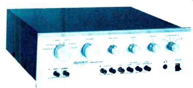
Dynaco's PAT-5 is a new solid-state design that super cedes as top of the fine their first transistor preamp, the PAT 4 which is still being made. Physically, the PAT-5 is quite similar to the PAT-4 but is deeper and uses push-button switches instead of rocker switches. The chassis is made up of three pieces: front subpanel, bottom plate, and rear panel. The top cover is a U-shaped piece which encloses the top and sides. Active circuitry is distributed among five PC boards: power supply, two output section amps, and two phono preamps. There is considerable hard wiring that interconnects back panel input and outputs to the selector switch, PC boards, and front-panel controls. An internal shield runs from front to back, separating the speaker selector switch, power supply, speaker input and outputs, and a.c. wiring from the rest of the unit. Rotary controls on the front panel are used for the selector switch, volume, balance, tone controls, and speaker selector switch. Push-button switches handle the tape monitor functions, mode, filters, tone control in/out, and "EPL" function. (EPL stands for External Processor Loop.)

On the rear panel are the signal input and output connectors, a.c. line cord, and convenience outlets, and six pairs of five-way binding posts for connection of the system power amp outputs and two pairs of speakers.
Circuit Description
As is fairly easy to see in Figs. 3 & 4, the PAT-5 has four amplifier blocks per channel: phono preamp, high-level-input voltage follower, high-cut filter amp, and tone control/output amp. The high-cut filter stage is completely bypassed when switched out. The high-level-input voltage follower, hereafter called the voltage follower, serves to present a constant input impedance (50 kOhms) for high-level inputs and to present a low output impedance to drive the parallel combination of the balance and volume control (10 kOhms).
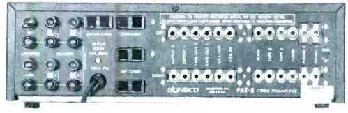
Fig. 1--Back panel view of the Dynaco PAT-5.
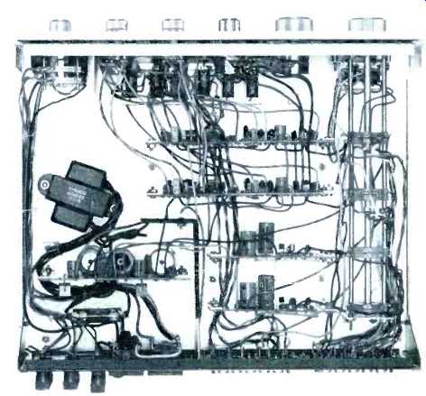
Fig. 2--Interior view.
From a signal flow standpoint, the input signal selected comes off of the selector switch and passes through the tape monitor and EPL switches to the input of the voltage follower. The EPL switch permits an external device, such as a frequency equalizer, to be switched in or out of the signal path at the input to the voltage follower. Coming out of the voltage follower, the signal passes in turn through the mode switch; low-cut filter, volume, and balance controls; high cut filter, and finally arrives at the input of the tone control/output amplifier. After passage through the output amp, the signal emerges at the main preamp outputs. From the foregoing, it is evident that a minimum of three amplifiers are in the signal chain when using the phono function. The phono preamp is a two-stage common-emitter circuit, with RIAA equalization accomplished in the feedback loop from second-stage collector to first-stage emitter.
Nominal 1-kHz equalized gain is 37 dB, although Dyna gives instructions in their manual for setting the gain from 34 to 43 dB in three dB steps. Further, one can wire the unit to have different gains for the phono 1 and phono 2 functions so that two different pickups can be used and have about the same output from the phono preamp.
The voltage follower is composed of a compound connection of opposite polarity transistors. The collector signal of Q301 drives the base of Q302, whose collector signal is all fed back to the emitter of Q301, thus forming a resultant emitter-follower with a voltage gain of about 1X. High-cut filter action is accomplished with an active lowpass filter, input emitter-follower Q303 presents a high-input impedance to the volume control and a low output impedance to the actual filter, which is a three-pole (three resistors and three capacitors) circuit involving emitter-follower Q304. Overall gain of the filter amp is slightly less than one.
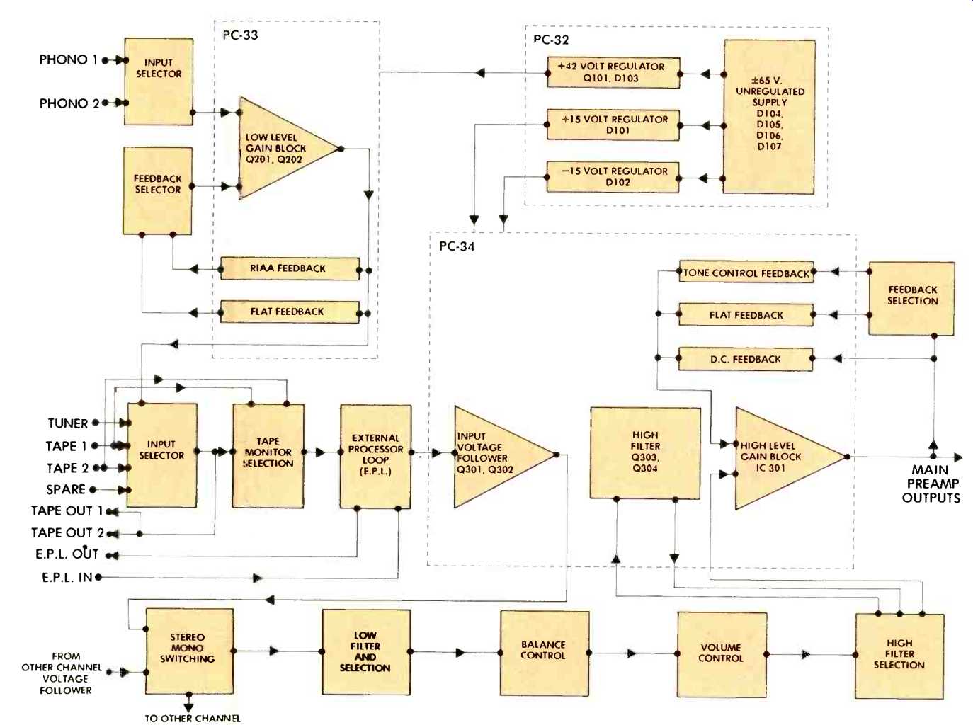
Fig. 3--Block diagram.
The final 20 dB of total preamp gain is generated by the output/tone control amp. This output amp is a LM301 operational amplifier connected in a tone-control circuit that so far has been used in three other firms in two preamps and an integrated amplifier. It has the advantage that output amplifier gain and tone-control action is accomplished in one circuit block, rather than two as is the common practice. Further, the circuit is noninverting and has high input impedance, allowing it to be driven directly from the volume control. The circuit arrangement of resistors, capacitors, and bass and treble control potentiometers is similar to the Baxandahl circuit used in many preamps but is different in two major respects. First, the control potentiometers are log taper, having 10 percent of total resistance from end to wiper at 50 percent mechanical rotation, and second, one of the two ends of the control pot divider string is grounded rather than being the signal input. The signal input for this circuit is the noninverting input of the op amp.
With the control pots at 50 percent rotation, these pots and associated resistors and capacitors form two frequency insensitive, 10/1 voltage dividers off of the amplifier output, with the wipers resistively summed into the inverting input of the op amp. This forms a closed-loop, noninverting, flat gain of 10X. Rotating either pot from center unbalances the frequency insensitivity of the associated divider and results in the closed-loop gain of the circuit giving a boost or cut in the associated frequency range. The tone control in/out switch, when out, substitutes a flat-resistive 10/1 divider for the feedback network around the output amplifier. An overall d.c. feedback loop is around the op amp, causing it to have a d.c. gain of one for good d.c. operating stability.
The power supply delivers Zener-regulated plus and minus 15 volts to the output amp and voltage follower and decoupled plus 15V to the filter amp. The raw, rectified plus d.c. is regulated by a Zener diode and emitter-follower to provide plus 42.5 volts to the phono preamps.
An interesting departure from conventional practice is used in the primary a.c. wiring of this unit. The circuit is always powered when plugged in, and the power switch merely controls the switched a.c. outlets. This makes good sense as the unit draws about 12 watts and, being continuously on, keeps the internal environment of the unit at a reasonably constant temperature, extending the life of components. Further, no annoying and potentially speaker damaging thumps occur when the entire system is powered on and off. Dynaco makes a concession to energy conservation purists by giving instructions for wiring the unit so that the preamp power is also switched by the power switch!
Listening Tests
The PAT-5 was first listened to as a phono preamp only, with output signal taken at the tape-out jacks, followed by a dual 50K volume control directly into the power amp. A Supex SD-900 and Fidelity Research FR-1 MK II were the cartridges used through the reviewer's own pre-preamp and into the phono 1 inputs of the preamp. Listening was done with Dahlquist DQ-10 loudspeakers on loan from the maker for these tests and Stax SRX MK2 phones.
This preamp has an open sound with good overall definition, though, like other transistor preamps, it has some high frequency edginess and irritation. Bass reproduction is solid and well defined and generally on a par with other top-quality solid-state preamps. Switching in the output section of the PAT-5 caused a noticeable decrease in definition and some increase in high frequency edginess. All controls operated well and with no noticeable switching pops or transients. The tone controls were judged particularly effective in making small corrections to the overall frequency response with different records and other program sources.
Kit Builder Comments
Although the PAT-5 was much easier to assemble than the ST-400 basic power amplifier (reviewed in Audio, p. 47, May 1975), it is not a kit I'd recommend to the beginning kit assembler because of the considerable amount of point-to-point wiring between the large selector switch assembly and the many input and output terminals (due to the unusually flexible input/output switching, as well as the EPL). The 35-page manual is Dynaco's usual thorough job of presentation, and it has a circuit diagram as well as a detailed functional block diagram, both necessary for complete understanding of the extra features. Also included is a 17-by-22 in., full-size wiring and assembly diagram, showing every wire and component, which I taped to the wall over my work bench. At the bottom of the diagram, there's a 16-in. scale for measuring wire cut from the four hanks supplied.
Most of the circuitry is on the four preassembled PC boards-two identical audio boards and twin preamp boards. The audio boards are connected to the rest of the components via 27 edge-mounted solder eyelets, while the preamp boards have nine eyelets each. Only the board for the regulated power supply required assembly. Its seven capacitors, six diodes, and three resistors took 20 minutes to mount and solder in place.
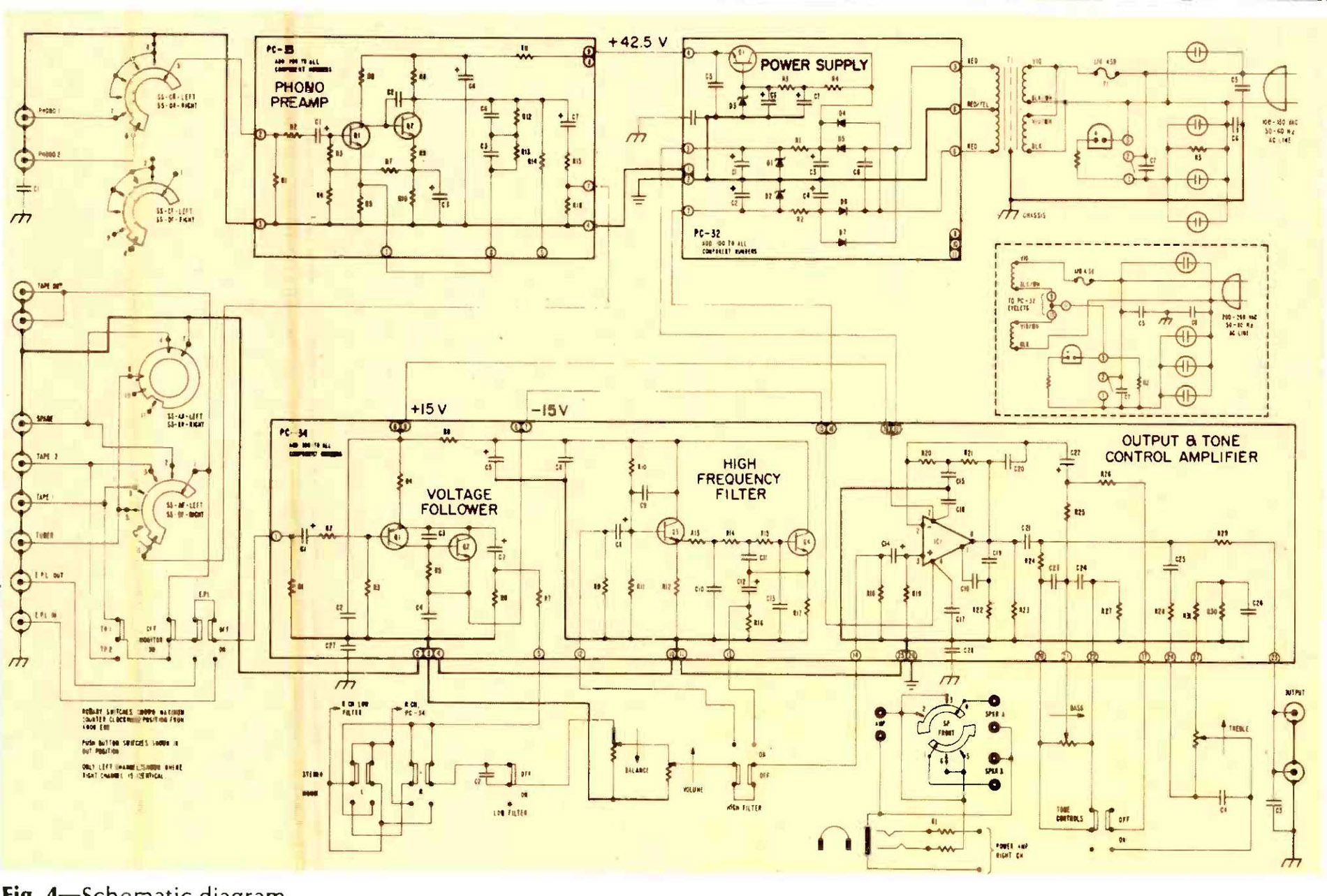
Fig. 4--Schematic diagram.
Dynaco divided the wiring and assembly into six sections which are listed below with the number of steps and the time required to finish each:
Because I made a couple of mistakes when I assembled the ST-400, I was especially careful in wiring the PAT-5. Either because it's a simpler kit or perhaps because I was more careful with this kit, it worked perfectly the first time I connected it to the system. If there'd been trouble, however, I probably would have been able to clear it up by using the information in the four pages of troubleshooting aids Dynaco supplied in the manual. These include pictorial layouts of the components on each board, with voltage tables for each board and for each transistor, diode, and the two ICs.
-Charles Graham.
Phono Preamp Measurements
Gain of the phono preamp at 1kHz measured 78X and 74X in the left and right channels respectively, which works out to 37.8 and 37.4 dB. Input noise with shorted inputs in a 400Hz to 20kHz band was 0.26 µV for left and right channels and with the measurement bandwidth extended to 20 Hz to 20 kHz band was 0.6 and 0.7 µV for both channels. The 20Hz to 20kHz noise was largely "1/f" or lower frequency noise and was relatively free of 60 Hz line harmonics. These are excellent noise figures and represent a phono signal-to-noise ratio of 83 to 84 dB below 10 mV at 1 kHz.
The 20 kHz THD, standard SMPTE IM, and CCIF IM for equal amplitude 10 and 11 kHz output levels are plotted in Fig. 5 vs. phono preamp rms output level. The data shown is for a high impedance measurement load at the tape-out jacks of the preamp. This presents the normal load to the phono preamp output, which is the 50-kOhm input impedance of the voltage follower. Loading the phono preamp output with 10kOhms increased all the distortion levels somewhat and reduced the maximum output before clipping, which can be seen most easily in the phono overload measurements shown in Table 1.* Standard SMPTE IM is quite low up to 7 V output. The 20-kHz THD is low up to about 3.5 volts and then climbs rapidly beyond 4 V. This rapid increase in THD above 4 V output is caused by the relatively low impedance reactive load of the RIAA feedback network upon the output stage of the phono circuit. Since the impedance of this network decreases with increasing frequency, it becomes more difficult for the output stage to swing to the lower frequency, lightly loaded voltage clipping level. This distortion in the region of rapid increase with output level is mainly even harmonic due to the output stage cutting off on the plus half cycle of the output voltage waveform. Since, due to the reactive nature of the load, the transistor output current is out of phase by some 60 to 80 degrees with the output voltage, the current cuts off when the output voltage goes past zero on the way to the positive peak of the sine wave. When this happens, the output transistor has lost control of the situation and the collector load resistor continues to pull the output positive but in a non sinusoidal manner. This same effect causes first-order difference tone generation in the CCIF IM test.
All of the above simply means that the output voltage deliverable at low distortion decreases as frequency increases.
This is not unique with the PAT-5 phono preamp but is characteristic, more or less, of all the two-stage, feedback-equalized phono preamps on the market. More sophisticated complementary output stage circuits can reduce this kind of distortion but don't necessarily sound better. The Dyna PAT-5 phono stage has enough high frequency input signal acceptance to not be in trouble with most all high-quality magnetic cartridges.
RIAA equalization error with a noninductive source is shown in Fig. 6. The broad rise between 50 and 500 Hz in the left channel plotted is enough to be audible as a slight upper bass heaviness. The right channel was considerably flatter in this region. The low-frequency rolloff with 10 kOhm loading is mainly due to the relatively small 1 NF output coupling capacitor. The effect of nonideal 47-kOhm input resistance and possible interaction of reactive sources on the feedback equalization was checked using representative low- and high-inductance cartridges. With the high-inductance cartridge source, the response was found to rise with frequency being up about 0.8 dB at 5 kHz, +1.6 dB at 10 kHz, +1.8 dB at 15 kHz, and +1.6 dB at 20 kHz. This is in contrast to other preamps tested which have tended to roll off the last octave by 1 to 2 dB. This characteristic would tend to make the PAT 5 sound slightly brighter than other preamps when using most magnetic cartridges which are high inductance types.
With the low-inductance source, the effect was much less pronounced and more like other preamps tested which, in general, tend to be up 0.3 to 0.6 dB from 3 to 20 kHz.
Phono overload vs. input frequency is shown in Table 1 below for an open circuit and 10-kOhm load at the tape-out jacks. Overload was judged visually on a scope and was either onset of peak clipping at low frequencies or the positive slope distortion at high frequencies discussed under distortion observations.
*Dynaco specifies 15 kOhms as the load.
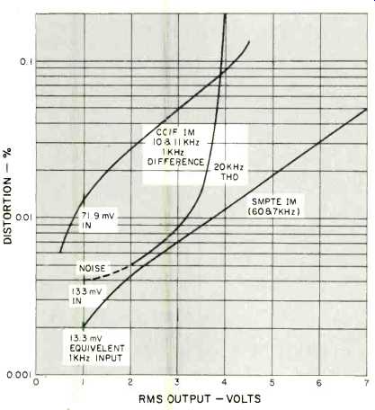
Fig. 5--Output voltage vs. CCIF and SMPTE IM and 20-kHz THD.
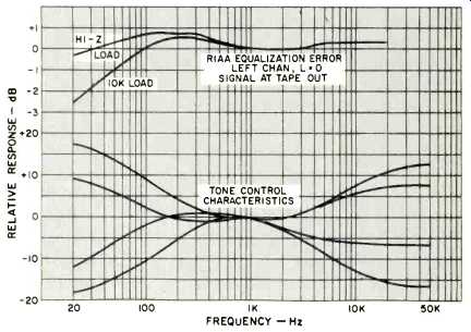
Fig. 6--RIAA equalization error and tone control characteristics. Dynaco specifies
15 kOhms as the load.
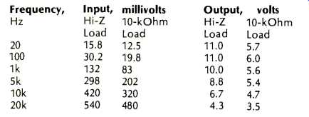
Table 1--Frequency and load vs. phono overload. Dynaco specifies 15 kOhms as
the load.
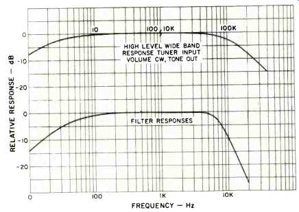
Fig. 7--Filter responses (lower curve) and high-level response (upper curve;
note break at 100 Hz/10 kHz).
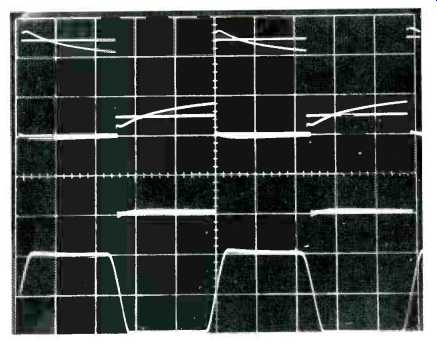
Fig. 8-Pre-equalized square-wave responses from phono preamp. Top, 40 Hz;
middle, 1 kHz; bottom, 10 kHz. (All outputs, 0.5 V/cm; inputs adjusted to overlay
outputs; top, 5 mS/cm; middle, 200 µS/cm; bottom, 20 µS/cm.) Scope photos of
pre-equalized square waves are illustrated in Fig. 8 for test frequencies of
40 Hz, 1 kHz, and 10 kHz. The rise time of the input signal is limited to 7
E6 to give an equivalent input bandwidth of 50 kHz. With a 10-kOhm load, the
low-frequency tilt shown for 40 Hz about doubled.
Channel-to-channel crosstalk of the phono preamp was measured on a pre-equalized basis and found to be down 80 dB or more from 100 Hz to 5 kHz, decreasing to-49 dB at 20 Hz and-68 dB at 20 kHz. These are quite good measurements for this test.
Output Section Measurements
Except where otherwise noted, the measurements of the output section are made with the filters and tone controls switched out. Signal input was into Tuner, output taken at main output with volume control at maximum.
Output section voltage gain was found to be 9.8X and 10.2X for left and right channels respectively, which works out to 19.8 and 20.2 dB. IM distortion was low indeed, being less than 0.002 percent for output levels of 7 V rms or below, with load resistances of 10 kOhms or higher. Harmonic distortion was also very low, being less than 0.01 percent for 20 Hz to 20 kHz at rated output of 2 V rms with a 10-kOhm load or higher. THD was highest at 20 kHz and was just under 0.01 percent. At 9 V rms output with a 10-kOhm load, THD was still under 0.01 percent from 20 Hz to 10 kHz and was 0.025 percent at 20 kHz. To get an idea of how low THD really was at mid frequencies, a wave analyzer was used to measure the distortion products at 2 V output at 1 kHz with a 10-kOhm load. The technique is to feed the wave analyzer from the distortion output of the Sound Technology 1700A THD meter. This keeps the fundamental out of the wave analyzer, reducing its own spurious responses to very low values and extends the percentage measurement range to the residual of the Sound Tech oscillator. This measurement yielded 0.0005 percent second, 0.0005 percent third, 0.00013 percent fourth, and less than 0.0001 percent fifth.
Extremely low measured distortion levels to say the least! High-level frequency response, along with filter responses, are plotted in Fig. 7. Tone control characteristics for maximum boost and cut and for boost and cut settings of plus and minus 6 dB at 50 and 19 kHz are shown in Fig. 6. The characteristics of this type of tone-control circuit are nicely revealed here, showing that the turnover frequency for bass boost and cut is clearly variable with amount of control rotation and that the treble turnover frequency is lower for cut than boost.
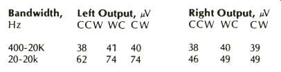
Table 2--Output section noise vs. volume control rotation and bandwidth. Notes:
CCW is counterclockwise; WC is worst case, usually about 6 dB down from maximum
position, and CW is clockwise.
A comment is in order here on the relation between mechanical and electrical center of the tone control pots. This type of circuit is sensitive to the accuracy of 10 percent resistance at 50 percent rotation in the control pots and to the tolerance in the associated resistors and capacitors. It was noticed that this factory wired unit didn't have equal rotation of the tone control knobs on either side of center, i.e. the knobs were adjusted on the shafts so that the response was flat with the tone controls engaged and the slots in the knobs were at 12'oclock. The kit instructions* tell the builder to put the knobs on so that the amount of mechanical rotation is equal on either side of center. When that was done with this unit, response was down 3 dB at 20 Hz and 2 dB down at 10 kHz. The effect of this on a 100-Hz square wave is shown in the middle trace of Fig. 9. If the kit builder wants flattest response with the tone controls engaged and knobs set at 12 o'clock, it would be wise to use an a.c. VTVM and oscillator and set the shafts for flattest response and then put the knobs on with slots straight up. Square-wave response at 20 Hz and 20 kHz is shown in Fig. 9. The 20-Hz tilt with a 10-kOhm or higher load was about the same, a good feature especially when driving a 10-kOhm input impedance power amplifier.
*Ed. note: Dynaco tells us that the first kit manuals were in error on this point. Subsequent printings describe approximate knob positioning correctly, so the knob rotates clockwise from 6 o'clock to 4 o'clock.
Output noise vs. bandwidth and volume control rotation is in Table 2. The higher noise level in the 20-Hz to 20-kHz measurement bandwidth was mainly due to line harmonics.
Switching the high-cut filter in caused the 20 Hz to 20 kHz noise be 75 and 72 µV in left and right channels respectively and was dominantly a high-frequency hiss increase due to the added noise of the filter amplifier. These output noise levels are in the area of possible audibility at the speakers if the speakers are high efficiency and the power amplifier used has higher than usual (28-32 dB) voltage gain.
Channel-to-channel crosstalk in the output section was measured and found to be greater than 80 dB down from 20 1500 Hz, decreasing to -70 dB at 4 kHz, -60 dB at 12 kHz, and-56 dB at 20 kHz.
In summary, the Dynaco PAT-5 offers good sonic performance and control features and would appear to be a good value for the money, especially if purchased as a kit.
-Bascom H. King
(adapted from Audio magazine, Feb. 1976)
Also see:
Dynaco Stereo 400 Power Amplifier (May 1975)
Dynaco AF-6 AM/FM Tuner (Equip. Profile, Sept. 1974)
Dynaco A-25XL Loudspeaker (Nov. 1976)
Dynaco Stereo 70 Series II Tube Amp (Nov. 1992)
= = = =