by W. Marshall Leach
Input and output jacks are grounded to the chassis at their mounting holes.
The maximum output power that a power amplifier can supply is limited by the peak voltage swing that it can produce with a given load impedance.
With a sine wave signal, the relation between the output power P, the peak output voltage swing VP, and the load impedance R1 is given by the equation:
P=V_p2 / 2Rt (eqn. 1)
For a fixed load impedance, it can be seen from this equation 40 that the maximum power is determined by the maximum peak voltage swing the amplifier is capable of. If this maximum peak voltage swing could be doubled, the power output from the amplifier would be quadrupled. This may seem academic, however, for the peak voltage swing that a given power amplifier is capable of cannot exceed the d.c. voltage on its power supply. (This assumes a direct-coupled amplifier for which positive and negative power supplies are used. In the case of a capacitively coupled amplifier with a single power supply, the peak voltage swing is limited to one-half the power supply voltage.) A simple technique for theoretically doubling the peak voltage-swing capability and thus quadrupling the power output of an amplifier is called strapping.
There is one catch, however. A strapped stereo amplifier becomes a mono amplifier. Thus two stereo amplifiers are required if a strapped stereo system is desired. This article describes a simple strapping circuit which can be used to strap any stereo amplifier for mono operation. The circuit has extremely low distortion and will in no way effect the sound quality that an amplifier is capable of.
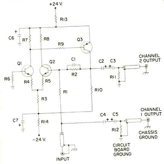
Fig. 1--Circuit diagram of the strapping circuit.
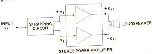
Fig. 2--Block diagram of the strapping circuit connected to a stereo power
amplifier. The loudspeaker is connected between the "hot" or positive
outputs of the amplifier. The loudspeaker ground connections for the amplifier
are not used.
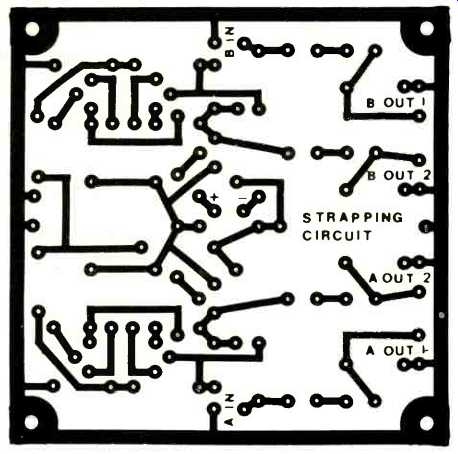
Fig. 3--Circuit board foil patterns for a two-channel version of the strapping
circuit. The view is from the copper side of the board.
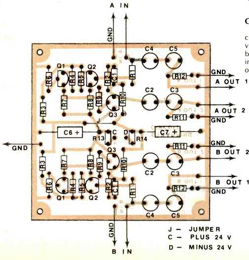
Fig. 4--Parts layout for the recommended foil patterns. The view is from the
side opposite the copper side of the board.
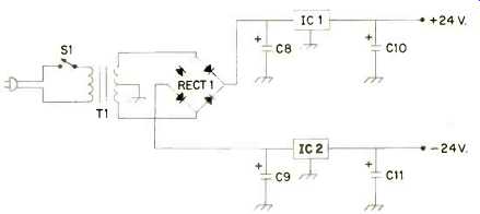
Fig. 5--Regulated power supply circuit diagram for the strapping circuit.
See text for proper grounding instructions.
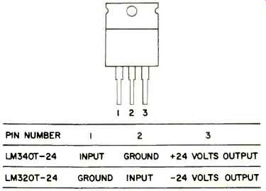
Fig. 6--Pin configurations for IC1 and IC2.
Circuit Description
The diagram for the strapping circuit is given in Fig. 1. The circuit is a three transistor discrete operational amplifier which is operated in a unity gain inverting mode. The input signal is split into two paths, one which feeds the channel one output and one which feeds the channel two output.
The channel one output is identical to the input signal with the exception that it is fed through the d.c. blocking capacitors C4 and C5.
The channel two output is derived from the input signal by the operational amplifier. The amplifier is connected so that its gain is unity, but it reverses the polarity of the input signal. Thus the channel two output is an inverted replica of the channel one output.
Let the strapping circuit be connected to a stereo amplifier as shown in the block diagram of Fig. 2. The speaker load impedance RI is connected between the two "hot" or positive outputs of the amplifier. It does not connect to the ground or negative outputs. Suppose a signal v1 is applied to the input of the strapping circuit. The power amplifier would then have a signal +v, applied to its channel one input and a signal-v1 applied to its channel two input. If the gain of each channel of the amplifier is K, it follows that the voltage across the speaker load is given by:
v = Kv1-K(-v1) = 2Kv1 (eqn. 2)
which is exactly twice what it would be if the amplifier were operated conventionally. Since the speaker voltage is doubled, the power is quadrupled. However, is the maximum power output capability also quadrupled? The answer is yes because the maximum peak voltage swing capability across the load is doubled.
The preceding discussion assumes the amplifier has a perfectly regulated power supply so that the d.c. supply voltage does not change when the amplifier load is changed. Since this is not true in practice, the maximum power output of a strapped amplifier will not equal four times its rated power into an 8-ohm load. However, it can be shown that a strapped amplifier will deliver to an 8-ohm load a power that is twice its rated per channel power into a 4-ohm load. For example, an amplifier may be rated at 100 watts per channel into 8 ohms and 175 watts per channel into 4 ohms. When strapped it will deliver 350 watts into 8 ohms. A strapped amplifier should not be used with a 4-ohm load, since this presents an equivalent per channel impedance of 2 ohms which may damage the amplifier or cause the protection circuit to trigger.
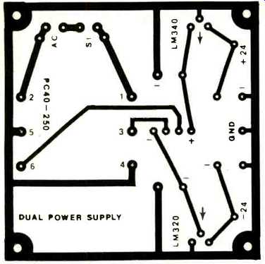
Fig. 7--Circuit board foil patterns for the regulated power supply. The view
is from the copper side of the board. The primary of transformer T1 solders
to terminals 1 and 2 on the circuit board. The d.c. resistance of this winding
is approximately 70 ohms.
The arrows point in the direction that the tabs on IC1 and IC2 face.
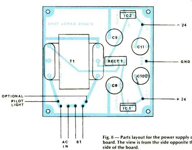
Fig. 8--Parts layout for the power supply circuit board. The view is from
the side opposite the copper side of the board.
Construction Details
The recommended circuit board foil pattern for a two-channel version of the strapping circuit is given in Fig. 3. The view in this figure is from the copper side of the circuit board. The corresponding parts layout for the circuit is given in Fig. 4. The view in this figure is from the side of the board opposite the copper foil pattern. To insure good continuity between circuit board ground and chassis ground, the circuit board should be mounted on metal standoffs with inside star lockwashers installed on each end. The mounting screws should be tightened securely so that the lockwashers make good electrical contact. To prevent ground loops, the input and output coaxial cables are grounded at only one end as shown in Fig. 1. Thus the signal ground connections are made through chassis ground.
The power supply for the strapping circuit is shown in Fig. 5. It can be used to power both the strapping circuit and the wide bandwidth preamplifier, which was the subject of a construction article in Feb., 1977, PROVIDED D1 through D4 are removed from the preamp and R31 through 34 are changed to 100 ohm, 'h watt resistors. Other recommended changes in the wide bandwidth preamplifier are R3 = 82 ohms, R9 = 3.9 Megohms, R21 = 3.3 Kilohms, C1 = 0.0022 microfarads, C8 = 220 picofarads, C9 = 5 picofarads, and C20 = 5 picofarads. These changes improve both the RIAA equalization and the transient response of the circuits.
The recommended circuit board foil pattern for the power supply is given in Fig. 7. The view in this figure is from the copper side of the circuit board. Figure 8 gives the corresponding parts layout. The view in this figure is from the side opposite the copper side of the board. The circuit board should be mounted on metal standoffs with inside star lockwashers installed on each end. This will insure good continuity between circuit board ground and chassis ground.
The mounting screws should be tightened securely so that the lockwashers make good electrical contact. IC1 and IC2 are installed vertically on the power supply PC board. It is not necessary to heat sink these if the power supply is used to power only the strapping circuit alone. However, if the power supply is used for other circuits requiring a ±24 volt regulated supply, the IC regulators may have to be heat-sinked. If the regulator metal tabs become too hot to continuously hold the little finger against, a metal heat sink of the spring clip-on variety or a screw-on type should be installed on both IC1 and IC 2.
Final Checkout and Turn-On Procedure
After the circuit is constructed, it should be checked out before using it with a power amplifier. First turn on the power and measure the d.c. voltages on C10 and C11. These should be plus and minus 24 volts, respectively. Next measure the d.c. voltage at the collector of Q3 on each channel.
This should be less than one volt. If these tests are positive, the circuit is operational and can be connected to the power amplifiers to be strapped. However, it is preferable that the unit be checked out with a signal generator and oscilloscope if these are available. A 1000-Hz signal connected to the in put should produce equal signal levels at the channel one and channel two outputs. With a dual trace oscilloscope, the inversion of the channel two output can be verified.
The strapping circuit should ALWAYS be turned on before the power amplifier in order to prevent any turn-on thumps from reaching the speakers. Similarly the power amp should be turned off before the strapping circuit. If desired, the strapping circuit can be left on at all times to prevent both turn-on and turn-off thumps. As a final precaution, do not strap a power amplifier that cannot drive the rated loudspeaker impedance. Low impedance loudspeakers should not be used with strapped amplifiers.
References:
1. W. M. Leach, "Construct a Wide Bandwidth Preamplifier," Audio, Vol. 61, No. 2, Feb., 1977, pp. 38-48.
Parts List:
Parts listed here are for a single strapping circuit and the regulated power supply. Resistors should be 1/4 watt carbon film units unless otherwise noted.
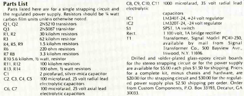
Q1, Q2 2N5210 transistors Q3 2N5087 transistor R1, R2 30 kilohm resistors R3 62 kilohm resistor R4, R5, R9 R6 R7 R8 R10 5.6 kilohm, R11, R12 R13, R14 C1 C2, C3, C4, C5 C6, C7 1.5 kilohm resistors 220 ohm resistors 3.3 kilohm resistors 1/2 watt, resistor 100 kilohm resistors 100 ohm,'h watt resistors 2 picofarad, silver-mica capacitor 100 microfarad, 25 volt radial lead electrolytic capacitors 100 microfarad, 25 volt axial lead electrolytic capacitors C8, C9, C10, C11 electrolytic IC1 IC2 51 Rect.
1000 microfarad, 35 volt radial lead capacitors LM340T-24, +24 volt regulator LM320T-24,-24 volt regulator SPST, 1A switch 1 100 volt, 1A bridge rectifier
T1--Transformer, Signal Model PC40-250, available by mail from: Signal Transformer Co., 500 Bayview Ave., Inwood, N.Y. 11696.
Drilled and solder-plated glass-epoxy circuit boards for the stereo strapping circuit or for the power supply are available for $5.00 each plus $1.50 for shipping. Prices for a complete kit, minus chassis and hardware, are $20.00 for the strapping circuit and $30.00 for the regulated power supply plus $2.50 shipping per order. Order from Custom Components, P.O. Box 33193, Decatur, GA 30033.
(Source: Audio magazine, Feb. 1979)
Also see: Link | --Build a Stepped Volume Control (Feb. 1979)
Build a moving coil phono pre-preamp (Feb. 1978)
= = = =