MANUFACTURER'S SPECIFICATIONS:
FM Tuner Section
Usable Sensitivity: Mono, 11.2 dBf (2.0 uV ); stereo, 19.2 dBf (5 uV).
50-dB Quieting: Mono, 17.2 dBf (4 uV); stereo, 37.2 dBf (40 uV).
S/N: Mono, 65 dB; stereo, 60 dB.
Frequency Response: 30 Hz to 15 kHz, +0.5, -2.0 dB.
Capture Ratio: 2dB.
Image Rejection: 45 dB.
I.f. Rejection: 80 dB.
Spurious Rejection: 80 dB.
AM Suppression: 50 dB.
THD: Mono at 1 kHz, 0.2 percent; stereo, 0.4 percent.
Stereo FM Separation: 37 dB at 1 kHz, 30 dB at 100 Hz and 10 kHz.
Muting and Stereo Threshold: 14.7 dBf (3 uV).
AM Tuner Section
Usable Sensitivity: 25 uV.
Image Rejection: 45 dB.
I.f. Rejection: 30 dB.
S/N: 40 dB.
THD: 0.8 percent.
Amplifier Section
Power Output: 40 watts per channel, 8 ohms, 20 Hz to 20 kHz.
Rated THD: 0.1 percent.
Rated IM: 0.3 percent (0.1 percent at 1 watt).
Damping Factor: 40.
Frequency Response: 20 Hz to 30 kHz ±1.0 dB.
Sensitivity: Phono, 2.5 mV High Level, 150 mV.
Phono Overload: 150 mV at 1 kHz.
S/N: Phono, 85 dB (re: 10 mV input "A" weighted); High Level, 95 dB (IHF "A" weighted).
Bass Control Range: ±12 dB at 100 Hz.
Treble Control Range: ±10 dB at 10 kHz.
High-Filter Cutoff: 6 kHz (6 dB/ octave)
General Specifications
Power Consumption: 130 watts, 120 V, 60Hz.
Dimensions: 19 in. (48.3 cm) W x 6 5/16 in. (16 cm) H x 14 5/8 in. (37.1 cm) D.
Weight: 25.3 lbs. (11.5 kg).
Price: $319.95.
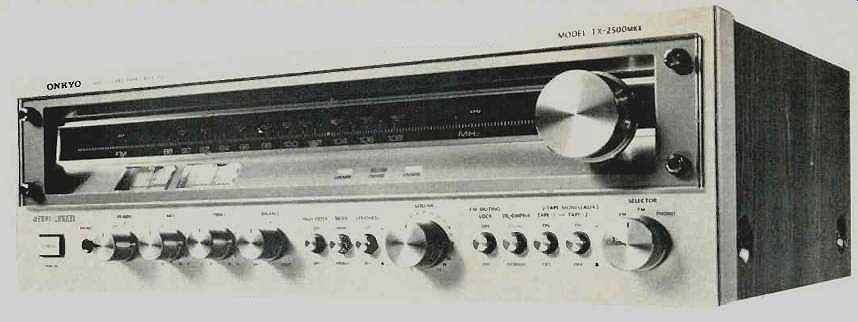
While some audio manufacturers tend to append their product model numbers with a "Mark II" or even a "Mark III" to justify a price increase or minor cosmetic change, that is not the case with the Onkyo mid-powered TX-2500-II stereo receiver. Compared with the earlier RX-2500, the new model's power output has been increased from a rated 27 watts per channel to 40 watts per channel and rated THD has been lowered from 0.5 percent to 0.1 percent. Onkyo's novel "servo-lock" tuning system has been carried over into this model and, although it operates in much the same way as their more expensive "quartz locked" tuning circuitry, it does not utilize a more expensive quartz reference oscillator.
The front panel of the TX-2500-II features a recessed pair of dial scales on a dark background with accurate calibration marks for FM frequencies at every 200 kHz. Signal strength and center-of-channel tuning meters are located on a sloped surface just below the frequency scales, as are three illuminated bars which are designated as "stereo," "tuned," and "locked." When the tuning knob is rotated to a frequency close to correct tuning, the "locked" light comes on. Releasing the knob at that point causes the AFC-like circuit to pull in the signal more accurately and the "tuned light" illuminates.
The remaining controls are located along the lower section of the panel and include a power On/Off switch , speaker selector switch, step-type bass and treble controls, balance control, step-type master volume control, and a three-position selector switch for AM, FM, or phono program sources.
A 'phone jack is positioned near the speaker selector, and two additional groups of pushbutton switches handle the high-cut filter, loudness, mono/stereo mode, FM muting (which, in its Off position also cancels the "servo-lock" tuning circuit), 25/75 microsecond de-emphasis selection, and two tape monitor circuits, which include dubbing capability from one tape deck to another. There is no AUX setting on the selector switch and therefore any high level program sources to be used must be connected via one set of tape inputs and the appropriate tape button must be depressed to listen to such auxiliary program sources.
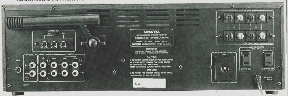
The rear panel of the receiver has screw-type connecting terminals for two pairs of speakers, one switched and one unswitched a.c. convenience outlet, antenna terminals for external AM and 300-ohm FM antennas, phono inputs, the two pairs of tape inputs and outputs, a chassis ground terminal, and the usual pivotable AM ferrite-bar antenna. Speaker protection fuse holders are also located on the rear panel.
Circuit Highlights
The FM front end of the TX-2500-II employs a dual-gate MOS-FET in the r.f amplifier. The i.f. stages contain four-element ceramic filters followed by a quadrature detector.
Stereo decoding circuitry is of the now-familiar phase-lock loop type. The power amplifier section is direct-coupled and equipped with thermal protection circuitry as well as speaker-line fusing. A complete schematic diagram was supplied with our test sample. Many of the circuit configurations include multi-purpose integrated circuits as, for example, the AM tuner section, the FM i.f. section, the multiplex decoder section, the phono pre-amp-equalizer, and the tone control amplifiers. The auto-lock circuit also utilizes an IC amplifier which results in an amplified or more sensitive AFC scheme.
While this auto-lock circuitry is not of the supremely accurate crystal-controlled variety found in Onkyo's top-of-the-line receivers, it does the intended job with more than reasonable accuracy and is a welcome addition at this price level.
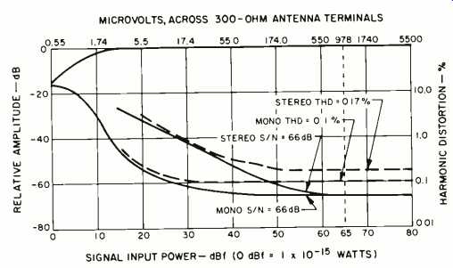
Fig. 1--Mono and stereo quieting and distortion characteristics in the FM
section.
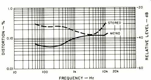
Fig. 2--Distortion vs. frequency in the FM section.
FM Performance Measurements
Usable sensitivity for the FM tuner section of this receiver measured 11.8 dBf (2.1 pV) in mono and 19.2 dBf (5 pV) in stereo. Reaching 50-dB quieting required signal strengths of 15.6 dBf (3.3 pV) in mono and 38.3 dBf (45 pV) in stereo. Best S/N in mono reached only 66 dB in mono with the same figure obtained in stereo. For a 1-kHz test signal, at 100 percent modulation, THD measured 0.1 percent in mono and 0.17 percent in stereo. Quieting and THD curves for a 1-kHz modulating signal are plotted against incoming signal strength in Fig. 1. Capture ratio measured a bit better than claimed, at 1.8 dB. Image rejection was 45 dB, the level Onkyo claims. The i.f. and spurious rejection both measured very close to the 80 dB claimed, while AM suppression measured 52 dB, a bit better than claimed.
Fig. 3--FM frequency response (upper trace) and the stereo separation. (Each
vertical division equals 10 dB.)
Fig. 4--AM frequency response.
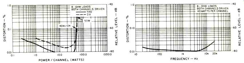
(left) Fig. 5--Distortion vs. output at 1 kHz. (right) Fig. 6--Distortion
vs. frequency.
Figure 2 is a plot of stereo and mono FM harmonic distortion at different frequencies. Counter to the usual situation, THD at low audio frequencies proved to be higher in mono than in stereo. Frequency response of the FM section, along with channel separation in stereo, is graphed in Fig. 3. The high-end response tended to rise a bit at around 10 kHz, but was perfectly flat (taking into account pre-emphasis and de-emphasis) at the 15-kHz audio extreme. Response was down some 2.5 dB at the 30-Hz low frequency extreme. Separation measured 44 dB at mid-frequencies, a slightly higher 46 dB at 100 Hz, and 38 dB at 10 kHz. Rejection of sub-carrier products was 39 dB, and the previously mentioned THD and noise measurements were measured, as shown, only with appropriate filters inserted between the outputs and the measuring equipment, as authorized by the IHF/IEEE Tuner Measurement Standards. Used with a stereo cassette deck, the amounts of high-frequency content (19 kHz and 38 kHz) in the output might affect Dolby recordings of FM programs adversely unless your tape deck is equipped with an MPX filter switch position. Muting threshold as well as stereo switching threshold were set at a satisfactorily low 14.7 dBf (3.0 uV).
AM frequency response of the tuner section of the Onkyo TX-2500-II is plotted in the spectrum analyzer 'scope photo of Fig. 4 and is essentially like the AM response of most stereo receivers we have tested, with rare exceptions. That is, roll-off begins below 100 Hz and above 2.0 to 3.0 kHz.
Amplifier Performance Measurements
The power amplifier section of the receiver delivered 50 watts of power at 1 kHz into 8-ohm loads before the rated harmonic distortion of 0.1 percent was observed. IM distortion reached its rated value of 0.3 percent when power output was increased to 53 watts per channel. At the published rating of 40 watts per channel, using a 1-kHz test signal, THD measured only 0.01 percent, while IM distortion measured 0.022 percent. These results are plotted in Fig. 5. As can be seen from the curve of Fig. 6, rated power output was easily obtained at the frequency extremes as well, with THD readings of 0.015 percent at 20 Hz and 0.027 percent at 20 kHz.
Our sample might well have carried a wattage rating of 43 watts plus and still conform to FTC power disclosure rules.
Power band (the frequency extremes at which rated power can be delivered at or below rated THD) extended from 12 Hz to 50 kHz.
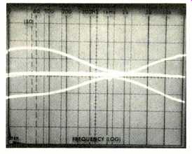
Fig. 7--Bass and treble control range.
Dynamic headroom of the power amplifier section measured 1.58 dB above rated continuous power output, while clipping headroom measured 1.18 dB above rated output.
Damping factor, measured at 50 Hz, was 40.
Frequency response, measured from the high level inputs to speaker outputs, was flat within 1.0 dB from 10 Hz to 30 kHz and within 3.0 dB from 7 Hz to 55 kHz. RIAA equalization of the phono preamp section was accurate to within a very fine ±0.1 dB from 30 Hz to 15 kHz. Phono input sensitivity (based upon the new reference level of 1-watt output) measured 0.35 mV, while high-level input sensitivity measured 24 millivolts for the same 1-watt output level. Phono overload, for a 1-kHz input signal, measured 175 millivolts.
S/N using the phono inputs, measured in accordance with the new amplifier standards, was 78 dB, "A" weighted, (re: 5-mV input, 1-watt output), while for the high level inputs, "A" weighted noise was 83 dB below 1.0 watt output, using a reference 0.5 volts of input.
Tone control range is plotted in the spectrum analyzer sweep photo of Fig. 7, and we noted that the turnover points for this tone control arrangement were set fairly high (at around 1.5 kHz to 2.0 kHz). The result of this (evident in our subsequent listening tests) is that when one attempts to add a moderate amount of bass boost to reproduced program sources, much of the mid-range is also affected. However, the treble controls affect less of the mid-range region as con figured in this design. The moderately sloped high filter response almost duplicates the action available in the treble-cut position of the treble control.
Use and Listening Tests
The amplifier section of the Onkyo TX-2500-II is, to our mind, the best part of this unit, and while the tuner section does come off second best in this internal match-up, it is no slouch either. To our ears, tonal quality of the amplifier section, when using good disc program sources or high quality tapes, was excellent. It seemed capable of delivering far more than its rated 40 watts under actual music listening conditions--this despite the modest dynamic headroom observed on the bench tests. Our listening tests were performed using a pair of relatively low efficiency bookshelf acoustic suspension speakers such as might logically be used in a medium priced component system using this receiver as its electronic section. In using FM signals as a program source, we did occasionally have some difficulty in separating weaker signals from close-in stronger signals that were nearby on the frequency scale, so if you plan to do any DXing of FM with this unit, a good directional outdoor FM antenna should be part of your system.
Considering its price and performance, plus the amount of upgrading that Onkyo has included in this revised version, the TX-2500-II gets a pretty fair grade overall.
-Leonard Feldman
-----------
(Audio magazine, Feb. 1979)
Also see:
Onkyo TX-61 Tuner Amplifier (Feb. 1983)
Onkyo T-9090II FM Tuner (Jul. 1988)
Onkyo Model A-7 Integrated Amplifier (Jan. 1978)
Onkyo DX-G10 Compact Disc Player (Mar. 1989)
Panasonic Model SA-5800 AM /FM Stereo Receiver (Aug. 1972)
= = = =