by B.-E. EDVARDSEN, P. W. MITCHELL, and J. JANDA
[Bjorn-Erik Edvardsen is Director of Research at the London headquarters of NAD International. Jifi Janda, responsible for the conception and development of the "floppy" tonearm, is a consultant to the Tesla Research Institute in Prague, Czechoslovakia. Peter W. Mitchell is an American technical writer and a consultant to NAD in Massachusetts. ]
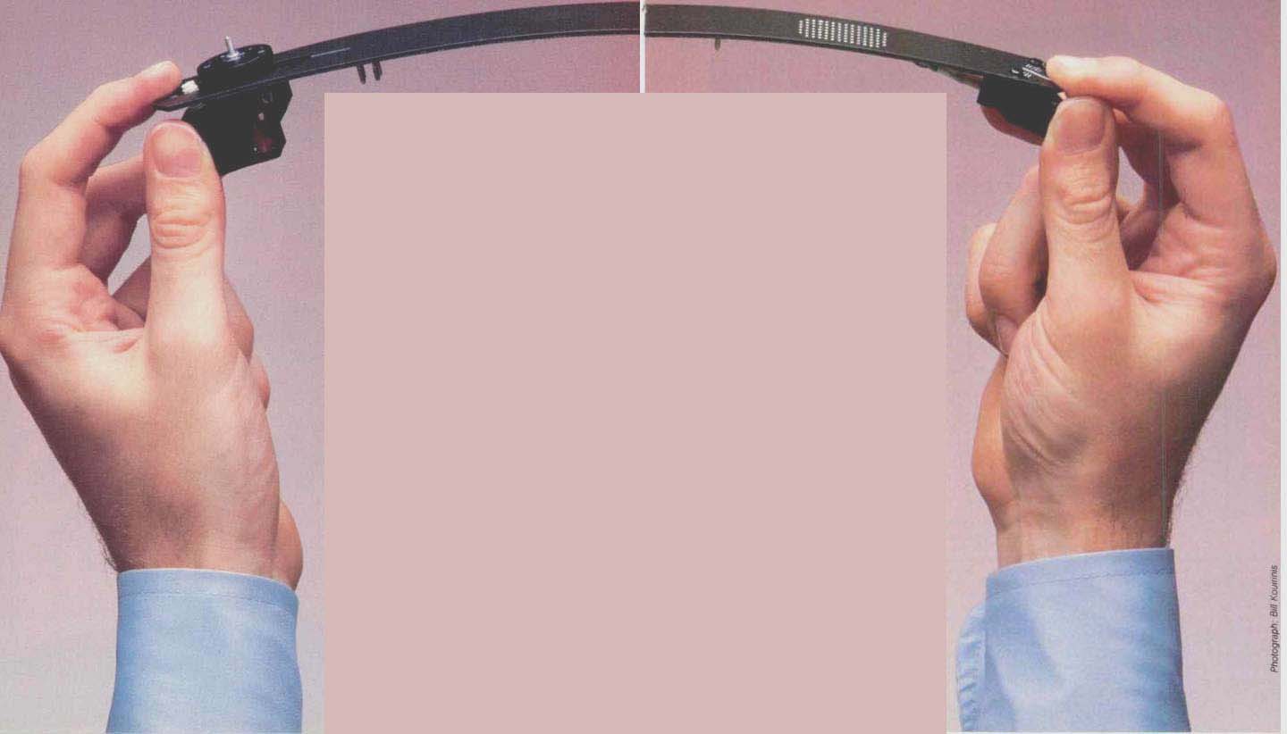
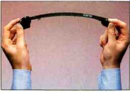
Not as limp as linguine al dente, the arm on NAD's 5120 still has raised quite a few eyebrows because of its highly-unusual flexibility. Many other aspects of the turntable are also the result of unconventional design approaches.
When the 33-rpm LP disc was developed at CBS Labs 35 years ago, , the word "microgroove" was introduced to describe it--meaning that the modulation in the grooves was microscopic in size, in contrast to the older, coarser shellac 78-rpm records. But in recent years it has become evident that many of the finer groove details in modern records are not merely microscopic, they are actually sub-microscopic in size. This is especially true in records with a particularly wide dynamic range. Since the maximum practical groove modulation is established by playing time and phono cartridge tracking limitations, an increased dynamic range can only be obtained by using smaller groove modulations for the quietest passages.
Groove modulation levels are expressed in terms of velocity, and any magnetic cartridge produces an output that is directly proportional to the velocity of the stylus tip. The velocity depends on the signal frequency, f, and on the groove modulation amplitude, A (the size of the wriggles, i.e. the distance that the stylus tip moves from side to side while tracing the groove), according to the equation: V = 2 π f A. Therefore, the size of the groove modulation is: A = V/(2 f). In record cutting, the standard reference level, corresponding to 0 VU on a tape recorder, is a lateral velocity of 5 cm/S at a frequency of 1 kHz. It turns out, therefore, that the groove modulation for this standard 0 VU level is only:
(5 cm/S) / (6.3 x 1000 Hz)
= 0.0008 cm, or 8µm,
where 1 µm is a millionth of a meter. The highest modulation velocities on a record, corresponding to the loudest peaks in music, are typically 15 dB above this 5-cm/S reference level [1]. The quietest passages can be more than 50 dB below the reference [2], for a total dynamic range of 65 dB, but this is an exceptional case. A more typical figure for the smallest modulations is 40 dB, which corresponds to a velocity (and amplitude) that is 1/100th of the reference level, i.e. 0.08 µm. Sub-microscopic indeed!
Visible light has a wavelength of approximately 0.5 µm, so this means that quiet passages in an LP record can have groove modulation amplitudes even smaller than a wavelength of light. Using an optical microscope, it is physically impossible to resolve anything shorter than the wavelength of the light being used, so it is easy to understand why the first really detailed photographs of record grooves were not obtained until the scanning electron microscope became available.
Obviously, in order to reproduce the quietest passages in modern LPs, the record playing system must be sensitive to extremely small stylus motions. But that means that the system will have virtually seismographic sensitivity to any vibration reaching the stylus. In addition to playing the music encoded in the groove, the "phonograph as seismograph" also "plays" the vibration spectrum of its environment, including the resonant vibrations generated in the player itself. Therefore, the fundamental problem in turntable design is the control of unwanted vibrations, whatever their source or path of propagation.
If the comparison to a seismograph seems inappropriate, recall that the record-playing system is a motion detector (the phono cartridge) whose low-frequency output is amplified by a factor of approximately 10,000 (for moving-magnet cartridges) or 100,000 (for moving-coil cartridges). This is the typical voltage gain from phono input to loudspeaker terminals, including RIAA equalization of + 17 dB at 50 Hz and assuming a volume control setting 15 dB below maximum.
Arm-Cartridge Resonance
In every tonearm there is a characteristic infrasonic resonance produced by the interaction between the compliance of the stylus assembly and the effective tonearm-cartridge mass. The resonance typically produces a peak of 8 to 15 dB in the frequency response of the system, somewhere between 6 and 15 Hz [3]. The amplitude of the peak indicates how much the cartridge and arm are overreacting, acting as a mechanical amplifier for any stimulus; a 12-dB peak means that the amplitude of the arm-cartridge motion is four times greater than the amplitude of the stimulus. Of course, normal musical signals on records are not low enough in frequency to stimulate this arm-cartridge resonance, but other stimuli are common: Warps and ripples in the surface of the record, and all of the external vibrations that pass through the turntable's suspension to the platter and tonearm.
Recall that the stylus is held in the groove by the vertical tracking force, which bears down against the upward restoring force supplied by the spring-like compliance of the stylus assembly.
Thus-in theory-the arm-cartridge mass is suspended at a constant distance above the record surface by a delicate balance of force and counter force. In fact, this precise balance is constantly disturbed by external vibration and by the undulations of the imperfectly flat disc surface. These cause the deflection of the cantilever to change, altering the balance of forces, and, once set in motion, the suspended mass will resonate up and down on its springy supporting compliance.
Thus, at a microscopic level (and sometimes at a plainly visible level), the arm/cartridge system is perpetually shaking up and down at its resonant frequency.
The effects of this resonance have been widely documented, notably by P. Ladegaard at Bruel & Kjaer [4]. Note that, while the arm and the cartridge body are vibrating up and down, the stylus tip normally stays in the groove.
So, as the height of the cartridge body above the disc surface varies, the vertical tracking angle and stylus rake angle change-and this is an immediate source of distortion.
Next, as the cantilever's deflection varies, the effective tracking force on the stylus is rapidly changing; it alternately digs into the groove with too much tracking force (creating the possibility of accelerated record wear) and nearly flies free with insufficient tracking force to hold the stylus in contact with the groove-and the result is mis tracking, with high distortion on musical transients and peaks. This rapid variation in effective tracking force, due to resonant arm/cartridge oscillation on a warped disc, is seen in Fig. 1 (reproduced from [4]). Since no cartridge is a perfectly linear transducer, any strong infrasonic vibration of the stylus will intermodulate with the musical signals in the audio frequency range, muddying the sound and producing further intermodulation in the loudspeaker if not filtered out. This is a common cause of muddy bass sound.
Finally, any up-and-down motion of the cartridge relative to the record surface produces a back-and-forth "scrubbing" motion of the stylus along the groove, causing frequency modulation of the recorded signal [5]. With a vertical tracking angle of 22° (typical of today's pickups), the scrubbing motion of the stylus along the groove is 40% as large as the vertical vibration. The audible result is flutter, and it occurs most strongly at a frequency of 10 Hz or less, where the ear is most sensitive to flutter.
Minimizing the influence of the infrasonic arm/cartridge resonance is, obviously, a desirable objective that has received inadequate attention from turntable designers. Of course, the severity of this resonance will be reduced if cartridge manufacturers include damping in their cantilever suspensions, but that can be done only to a limited degree, as it tends to degrade the tracking ability of the cartridge [6]. The "dynamic stabilizer" brush which is affixed to many of the Shure Brothers pickups provides effective damping, but a solution is still needed for other cartridges.
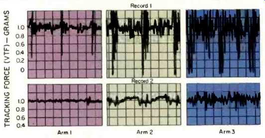
Fig. 1--Dynamic variation of the effective vertical tracking force during
two revolutions of a warped record (upper curves) and of a visibly flat disc
(lower curves), with three tonearms differing in effective mass. After Poul
Ladegaard's "Audible Effects of Mechanical Resonances in Turntables."
The Floppy Tonearm
A tonearm must be a stable carrier for the cartridge, must hold it in a level position tangential to the groove (as nearly as possible), should be low in mass, should be reasonably free of resonances, and must have wiring to carry the signal. The usual design solution involves a low-mass plug-in head shell; a rigid, precision-tooled tube of anodized aluminum, carbon fiber, or more exotic materials; an even more precisely machined set of pivots and bearings, and some flexible wires.
The most novel element in NAD's new tonearm is its construction. Not tubular, it is a flat arm made of the copper-clad fiberglass material used for printed circuit boards. The wiring from the cartridge to the pivot is etched on the underside of the arm, and the wide copper-clad area surrounding the signal wiring forms a ground plane that provides electrostatic shielding against hum pickup. The 1-inch width of the flat arm makes it extremely rigid in the lateral plane, more rigid than a thin-walled metal tube can be. However, since it is only 1.5 millimeters thick, the fiberglass arm is relatively flexible in the vertical plane, a characteristic which is both interesting and controversial.
All tonearms have some flexure. With tubular metal arms, the primary flexure mode typically occurs at upper-bass and lower-midrange frequencies, and if the material of the arm is not well damped, the energy absorbed in the flexure mode may emerge as resonant ringing. It is this potential ringing in metal tonearms which has led to the common assumption that all tonearm flexure must be minimized. The vertical flexure of this floppy arm is therefore likely to prove controversial. But unlike metal, the fiberglass material has high internal damping at midrange frequencies.
Tonearm flexure produces a notch in the frequency response of the cartridge. Because of the new arm's flexibility in the vertical plane, the primary notch occurs not in the midrange but in the deep bass-around 25 Hz in the early prototype arms, in which the counterweight was fairly rigidly coupled to the rear of the arm. A mathematical analysis by James V. White (formerly of CBS Labs) showed that this low-frequency flexure mode could be put to good use. By making the mount for the counterweight more compliant (actually suspending the counterweight on a spring), the notch was moved down to around 10 Hz, where it coincides with-and tends to cancel-the resonant peak in the arm cartridge response.
In other words, the flexure of the arm-counterweight system provides a new way to control the problematic resonance of the arm-cartridge system. The flexible tonearm and spring loaded counterweight function as a "dynamic vibration absorber" (DVA). Mechanically, what happens is that unwanted vibrational energy from the arm-cartridge resonance propagates up the length of the flexible arm, where it is transformed back into kinetic energy, setting the counterweight into vibration at the same frequency.
In essence, energy from the resonance is subtracted from the front of the arm (where it produces unwanted cantilever flexing and other difficulties) and is transferred to the back of the arm, where it is relatively innocuous.
Another beneficial effect is that the arm's vertical flexure partially decouples the front end of the arm (with the cartridge) from the remainder of the arm and the counterweight, thus lowering the effective inertial mass of the arm. A cartridge mounted in the flexible arm will therefore resonate at a higher infrasonic frequency than in a conventional rigid arm of the same static inertial mass.
Fundamentally, this is not a new idea. A counterweight often is mounted via a rubber decoupling sleeve, rather than being bolted rigidly to a tonearm, and the compliance of the sleeve produces DVA properties in the counterweight at some frequency. However, this phenomenon usually occurs in the 30 to 100 Hz range, where it cannot be of any benefit.
The DVA system designed for the flexible tonearm is illustrated in Fig. 2.
The counterweight is pivoted from a hinge point at its front end. The main mass of the counterweight (its rear portion) is free to move vertically, suspended on a coil spring whose stiffness is adjustable. Its resonance frequency is tunable in the 7 to 14 Hz range by means of a screw attached to the top of the spring, aligning with a frequency scale on the counterweight.
Thus, the DVA is tunable by the user to match the frequency of the arm-cartridge resonance. The large infrasonic resonance peak that occurs in a rigid tonearm becomes a pair of smaller peaks which straddle the notch produced by the flexible arm and tuned counterweight assembly.
To stabilize the infrasonic behavior of the system still further, a viscous damping mechanism has been incorporated into the counterweight assembly, consisting of a vial of silicone oil and a threaded rod. The damper is essential, since it absorbs the vibration of the counterweight and thus dissipates the energy that was subtracted from the arm-cartridge resonance by the floppy arm and DVA. The damping effect is adjusted by varying the depth of the rod in the oil, turning it until its tip aligns with scale gradations from 0 to 3 on the side of the counterweight, representing the range from no damping to heavy damping.
The damping blends the DVA notch and the resonance peaks into the smooth, controlled response illustrated in Fig. 3. In the vertical direction, where disc warps occur (upper curves), the result is a weakened resonance. In the 45° direction of the stereo groove modulation axes (lower curves), the resonance virtually disappears! Incidentally, in the 45° curves a 1-dB dip in response can be seen in the response of the floppy arm at about 140 Hz. This is present only in the right channel, and it is due to torsional flexure of the arm, caused by the fact that the center of gravity of the cartridge is not on the arm's central axis. This minor flexure mode could be eliminated, but it is not clear that the cost of doing so would bring any sonic benefit. As noted above, the fiberglass arm does not ring the way a metal arm does.
The tonearm for the new turntable is assembled from commonly available materials and easily manufactured parts. To obtain an effective arm mass of less than 8 grams, no headshell is provided. The entire arm is a plug-in unit, with its hardware located at the pivot where it contributes nothing to the effective mass of the system. In fact, the entire vertical pivot assembly is just a standard DIN socket, mounted in a sleeve on a pair of screws whose conical tips, precisely machined and hardened, function as low-friction cone bearings. Four metal pins on the tone arm fit the DIN socket, providing at once both the electrical connection and the mechanical installation of the arm. An audiophile who uses multiple cartridges can install each pickup in its own arm and can preset the tracking force and other adjustments; swapping cartridges is as simple as unplugging one arm and plugging another in.
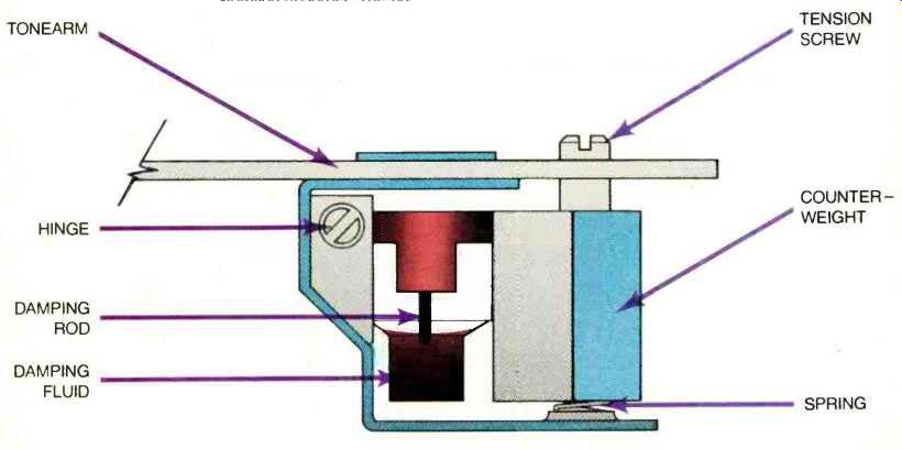
Fig. 2--A counterweight assembly that functions as a dynamic vibration absorber.
The counterweight is mounted on a hinged bracket, with its weight supported
on a spring whose tension is user-adjustable to set the resonant frequency.
The tip of a threaded rod is inserted into a vial of silicone fluid to provide
viscous damping.
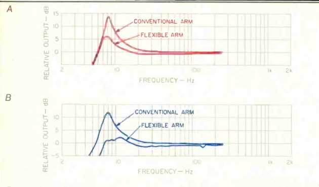
Fig. 3--The infrasonic response of a cartridge in a straight low-mass tubular
tonearm, and the same cartridge measured in the floppy tonearm. The upper graph
(A) shows the response to vertical modulation; the lower graph (B) shows pure
left or right-channel modulation.
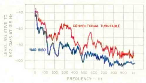
Fig. 4--The "microphonic" response of two turntables, which were
measured by placing the stylus in the groove of a non-rotating record and exposing
the turntables to a sound field of 95 dB SPL white noise. The NAD 5120, whose
platter and tonearm are isolated on a floating subchassis, is 10 to 20 dB less
sensitive to acoustic feedback than the conventional turntable, the NAD 5025,
which relies on compliant feet for isolation.
Suspension as Filter
The human ear is extremely sensitive at mid-treble frequencies, with hearing thresholds approaching 0 dB SPL. But at low frequencies the ear is very insensitive; at 30 Hz the threshold of audibility is about, 60 dB SPL, and at still lower frequencies only large vibrations are either heard or felt.
The shelf or cabinet that the turntable rests on is a sounding board. At a microscopic level it is continually stimulated by structure-borne vibrations from street and rail traffic, furnace blowers, refrigerator and air-conditioner compressors, and even loudspeaker-cabinet vibration. But since human hearing is completely oblivious to this perpetual low-frequency rumble, we can easily forget how sensitive the record-playing system is to such vibration, and how important it is to prevent it from reaching the record and stylus.
There are two ways to minimize the influence of structure-borne vibration on a turntable. One is to assemble the entire turntable as a rigid unit; make it heavy (so that it will resist being set into vibration), employ non-resonant materials wherever possible, and mount the assembly on compliant feet (made of springs and soft rubber) for isolation. The other approach is to mount the platter and tonearm together on a subchassis that floats on compliant springs, isolated from everything--including the exterior parts of the turntable itself.
In either case, it is the compliance of the system that determines how well isolated the .record and stylus are from structure-borne vibration. Any suspension or compliant support has a resonance frequency, related to its compliance and to the mass it is supporting.
Above its frequency of resonance, the suspension is an effective mechanical filter, preventing the transmission of vibration. Vibrations below the resonance frequency will pass freely through the suspension, shaking the record and stylus. Logically, then, the suspension resonance ought to be placed at the lowest practical frequency in order to narrow the range of the vibrations that can possibly reach the stylus.
Depending on the amount of damping employed, the suspension resonance may actually increase the amplitude of vibrations at or near the resonant frequency. For this reason the suspension resonance should not be located at or near the frequency of the stylus-tonearm resonance (usually between 7 and 15 Hz), where any unwanted vibration will be doubly amplified. If these resonances do coincide or overlap, the user is likely to experience frequent problems with acoustic feedback or resonance-induced flutter, and may be forced to install additional vibration absorbing or damping materials beneath the turntable.
Turntables that employ compliant feet for isolation usually have a resonant frequency of 10 Hz or higher, because a more compliant suspension would make the entire turntable too unsteady-rocking or bouncing when any of the operating controls were touched. In a floating subchassis design, however, there is no obstacle to placing the suspension frequency below 4 Hz, and this is the approach taken in the AR, Linn Sondek, and Oracle turntables, as well as the new NAD turntable discussed here. The platter and tonearm are mounted together on a rigid platform so that if any infrasonic disturbance does get through the suspension, the platter and stylus will tend to move together, minimizing the unwanted stylus deflection [7]. The platform is supported on three springs whose compliance allows the platter to move freely in any direction by at least 3 millimeters before encountering significant resistance.
There is, however, one disadvantage to a very low suspension frequency. Wooden floors often have a springy resonance at a similarly low frequency, so that footfalls or dancing may cause groove-jumping. As annoying as this may be, it has the advantage (unlike other suspension-induced problems) of being an obvious flaw that the user can take steps to correct.
One immediate advantage of the floating subchassis approach is that it isolates the stylus from the base and dust cover. Every turntable is "micro phonic" to some degree-responding directly to sounds in the room (including the output from the loudspeakers). The dust cover, being a large but thin and stiff object, is especially efficient at intercepting airborne vibrations and coupling them into the platter.
The importance of this is easy to demonstrate. Place the stylus tip in a record groove with the platter stationary, and play pink noise through a loudspeaker located several feet away. Set the volume so that the sound level measured near the turntable is about 90 dB SPL (measured on the "C" scale, i.e., without A-weighting), and connect the output of the cartridge to an oscilloscope or spectrum analyzer. Typically, in a turntable without a floating subchassis the microphonic pickup will be only 30 to 40 dB below normal musical signal levels. This coloration can be reduced by 10 dB or better, simply by placing a pillow on the dust cover to deaden it or by completely removing the cover.
Figure 4 illustrates the acoustic sensitivity of two turntables, measured as described above. Over a broad frequency range the NAD 5120 turntable, with its floating subchassis, is 10 to 20 dB less microphonic than a conventional turntable (the NAD 5025) that relies on compliant feet for its isolation.
Motor and Platter Vibration
Of course, the vibration of the drive motor is an important problem in any turntable. In principle, excellent performance can be obtained with either a direct-drive or a belt-drive system, but only a belt drive fits our requirements for low cost, easy manufacturability, and compatibility with a floating sub chassis suspension. This choice avoids both the cogging (torque pulsations) of inexpensive direct-drive systems and the complexity (which translates into high cost) of the more refined, high-performance direct-drive mechanisms. An inexpensive, a.c. synchronous motor provides accurate speed and is bolted to the turntable's base, where its slight vibration is inconsequential. Its torque is coupled to the floating platter via a thin neoprene belt that is taut enough to carry power to the platter at its desired rotational frequencies (0.55 and 0.75 Hz, i.e., 33 and 45 rpm), but is far too flexible to transmit higher frequency vibrations with any great efficiency. A suitable belt/platter resonance frequency is therefore around 2 Hz.
The floating suspension is so compliant that even the slight tension of the drive belt was enough to pull the platter off-center, toward the left-rear corner of the turntable where the motor is located. A spring was added in the right-front quarter to keep the floating subchassis in the correct centered position.
It has become traditional in turntable design to use the flywheel inertia of a massive metal platter as a mechanical flutter filter, in order to minimize the influence of bearing irregularities, torque pulsations in the drive, etc.
There are well-known disadvantages to this approach, however. One is the need, in many cases, for dynamic balancing of the platter after it is cast, in order to avoid an eccentric mass distribution that would increase wow and bearing wear. Another is the bell-like resonance of the metal platter itself; the greater the platter's mass, the more mechanical energy it can store when stimulated into vibration, and the more difficult it becomes to damp this ringing with a vibration-absorbing rubber platter mat. The importance of this problem is testified to by the widespread marketing of specialized platter mats.
These problems can be eliminated at their source. With a belt drive to filter out motor-induced flutter and rumble, and with the smooth platter rotation provided by a highly polished, hardened steel spindle shaft rotating in a close-fitting, self-lubricating sleeve bearing, there simply is no need for the flywheel effect of a metal platter. Instead, the new turntable employs a rubber platter, 7 millimeters thick.
In addition to having no resonance of its own, the rubber platter damps the vibrations which arise in the LP record itself. LPs are large, thin, and rigid, and so they are naturally microphonic, picking up sound from the air and coupling it to the stylus. Additional vibration is induced in the disc by the inertia of the stylus vibrating in the groove, as a consequence of Newton's Third Law of Motion (action produces reaction). Critical listeners may wish to obtain maximum damping of disc vibration by purchasing a spindle clamp to press the disc down, forcing discs with slight dish warp into uniform contact with the rubber platter.
To guarantee a flat contact surface for the LP, the rubber mat is supported by a lightweight aluminum disc that is curved up at the rim for stiffness. That disc has its own potential for resonance, of course, so the rubber platter increases to 9 millimeters thick near its rim and wraps around the edge of the disc, helping prevent any ringing.
In the course of developing the 5120 turntable, new solutions were found for the vibration-control problems that every turntable manufacturer must face.
One of these solutions (the stiffened rubber platter) effectively eliminates the minor but common problem of metallic platter resonance. Another-the use of a flexible tonearm and a tunable, spring-suspended, viscous damped counterweight functioning as an adjustable dynamic vibration absorber--effectively tames the infrasonic arm-cartridge resonance, which has been a major unresolved problem in real-world turntable performance. In addition, the traditional floating sub chassis suspension proved to be an economical and effective barrier to both structure-borne and airborne vibration.
As analog LP discs continue to improve in quality, thanks to better mastering and pressing techniques, it becomes increasingly important to eliminate subtle flaws in turntable performance. We hope that the ideas described here are a useful step in that direction.
References
1. Anderson, Roger, et al., "Phonograph Reproduction--1978," Audio, Vol. 62, No. 5, May 1978.
2. Pruitt, Robert L., "Macro Microgroove Model," CAS '80 Conference (Discwasher Inc.).
3. Happ, L. and F. Karlov, "Record Warps and System Playback Performance," Journal of the Audio Engineering Society, Vol. 24, No. 8, Oct. 1976.
4. Ladegaard, Poul, "Audible Effects of Mechanical Resonances in Turntables," B & K Applications Note 17-233, 1978.
5. Anderson, Roger, "A Vibration Stabilizer System for Phonograph Reproduction," AES Preprint No. 1356, May 1978.
6. Lipshitz, Stanley, "Impulse Response of the Pickup Arm-Cartridge System," JAES, Vol. 26, No. 1/2, Jan./ Feb. 1978.
7. Villchur, Edgar, "A New Turntable Arm Design," Audio, "Part 1," Vol. 46, No. 9, Sept. 1962; "Part 2," Vol. 46, No. 10, Oct. 1962.
Editor's Note: An "Equipment Profile" on the NAD 5120 turntable appears in this issue. In his abbreviated report, Edward M. Long paid particular attention to the tracking and isolation qualities of the turntable. -E.P.
Also see: NAD 5120 Turntable (Equip. Profile, Feb. 1984), Understanding Tonearms (June 1980)
(adapted from Audio magazine, Feb. 1984)
= = = =