by JOHN H. ROBERTS
[John H. Roberts is President of Phoenix Systems, Manchester, Conn.]
Taping from high-quality disc pressings routinely tests the dynamic range of even the highest-tech cassette decks, and CDs are even more of a challenge to tape adequately. All the new, top-line decks come with such powerful noise-reduction (NR) systems as dbx or Dolby C, which help recordists handle today's very dynamic program material. But for those whose decks have no noise reduction or only Dolby B NR, I've devised a low-cost, add-on companding noise-reduction system with which their decks can handle the hottest signals, just like the best new equipment.
The theory behind companding NR stems from the observation that tape hiss is effectively masked by loud music, and is only audible during quiet passages. Companding NR (like dbx and the two Dolby systems, which work on similar principles) is a two-part, encode/decode process. A compressor circuit in the record encoder reduces gain for signals above a certain level (the circuit's unity-gain threshold, or 0-dB level), and increases it for signals below that level.
This brings loud passages down below the limits of the tape deck's headroom and lifts quiet passages above the deck's noise floor. A complementary circuit in the playback decoder expands the signal back to normal, boosting the loud passages and cutting back on the soft ones. In the process, it also cuts back noise (Fig. 1). Thus, companding not only reduces tape noise but increases headroom, for cleaner and louder musical peaks.
The P-522 Noise Reducer
The Phoenix Model P-522 noise reducer, for which plans are given here, contains two simultaneous encode/decode channels (Figs. 2 and 3), allowing off-the-tape monitoring with natural dynamics when recording with three head decks. Its operation is based on wide-band, 2:1 compression/expansion, and will deliver the same order of S/N improvement as the dbx systems (although no attempt has been made to make the two compatible).
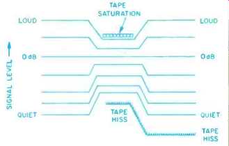
Fig. 1--How companding works.
Most companding NR systems rely on identical but inverse distortion in the playback expander to cancel out the third-harmonic distortion caused in the compressor by the audio signal modulating the gain-control voltage. The P522 electronically cancels out this modulation at the compressor. Reducing this distortion at the source is advantageous, since imperfections in the tape record/playback process can affect the ability of conventional systems to cancel out this distortion. However, crossing the P-522 with a conventional compander, by using one system to decode tapes made with the other, will yield higher distortion than will either system decoding its own tapes. Also, this new approach to modulation-distortion control uses different optimum attack/release time constants, so some dynamic mistracking could also occur.
For anything but noncritical applications, I do not suggest mixing different types of noise reduction. If you have an older-type NR (such as Dolby B) in your deck, just switch it out when using the new compander. Do not use them both at once, as you will get no further improvement in S/N, but you may over compress the highs and produce a loss of frequency response.
I have, however, found that playback of P-522 tapes in the car with no decoding at all can be quite acceptable, becoming less acceptable as the car system's frequency response and dynamic range begin to approach those of a good home system.
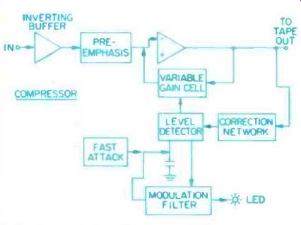
Fig. 2--Block diagram of the compressor section.
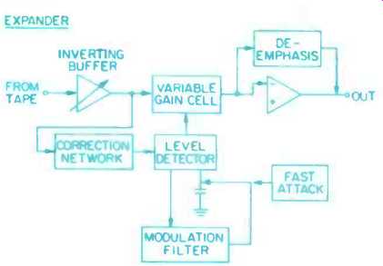
Fig. 3--Block diagram of the expander section.
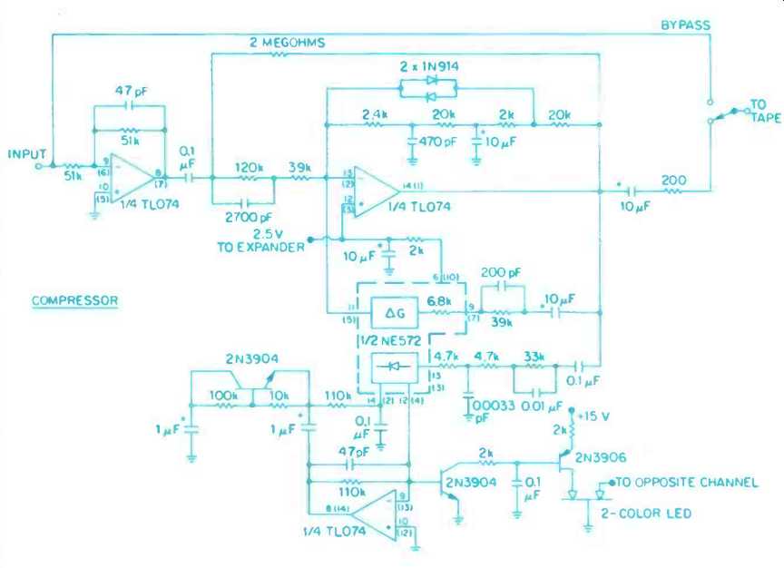
Fig. 4--Schematic diagram of the compressor section. Pin numbers shown on
ICs here and in Figs. 5 and 6 are for left channel; numbers in parentheses
are for right channel.
Power connections (not shown) are: +15 V to each NE572 pin 16 and TL074 pin 4,-15 V to each TL074 pin 11, and ground to each NE572 pin 8.
The P-522 uses high-frequency pre- and de-emphasis to reduce the audibility of tape hiss when only low-frequency signals are present. A correction network at the input to the level sensing port prevents solo high-frequency signals from being over-recorded. In fact, the network intentionally overcorrects, so high-frequency signals when present alone will be recorded slightly cooler than low-frequency signals. This reduces tape saturation and frequency response problems commonly experienced with unprocessed cassette recordings. Dynamic tracking errors can occur if the frequency content at the input to the playback expander is much different than the output of the record compressor.
An adaptive high-pass filter in the compressor attenuates low-level, low frequency signals caused by warped record and rumble, before they can get encoded. This is important because tape recorders generally have limited frequency response in the low bass and would not reproduce the warp signal, which has peak energy in the 5-Hz region. To further reduce this sensitivity to signals that the tape recorder can't reproduce, the input to the gain-control detector is rolled off below 38 Hz and above 20 kHz. (Note: As Dolby NR does not reduce noise at low frequencies, it will not be tricked by low-frequency response errors; however, it shows the same sensitivity to high-frequency errors as do all companding systems.)
Using the P-522
The P-522 is designed to hook up between a control preamp and a tape deck. Its only front-panel controls are on/off and in/out (bypass) switches.
Without noise reduction, setting record level is a juggling act between distortion, high-frequency saturation, and tape hiss. As the noise reduction gives you more than 20 dB of hiss reduction, the optimum 0-dB record point moves down quite a bit below meter 0 dB. I have found-6 dB to be a good setting on a few two-head machines I've worked with, but it's better (and fairly easy) to find the best recording level settings for your tape and machine by ear.
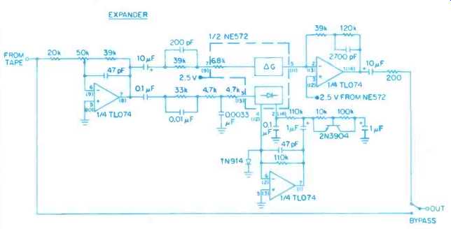
Fig. 5-Schematic diagram of the expander section.
===============
PARTS LIST:
Resistors, ¼-Watt, 5%
Value, Ohms Quantity
Semiconductors:
1N9' 4 diode 6 10 8 1N4002 diode 4 200 5 2N3904 NPN transistor 6 2k 6 2N3906 PNP transistor 2 2.4k 2
Two-color LED 1 4.7k 8 78L15, +15 V regulator 1 10k 4 79L15, 15 V regulator 1 20k 6 TL074CN op-amp 3 33k 4 NE572 compander IC 2 39k 10 51k 4
Capacitors:
100k 4 Value Quantity 110k 8 120k 4 47 pF, 10%, ceramic disc 8 2M 2 470 pF, 10%, ceramic disc 2 0.1 µF, 20%, ceramic disc 9 0.02 µF, 500 V, ceramic disc 1
Miscellaneous:
200 pF, 5%, polystyrene 4 2700 pF, 5%, polystyrene 4 DPDT push-push switch 1 0.0033 µF, 5%, polyester 4 4PDT push-push switch 1 0.01 µF, 5%, polyester 4 Phono jacks 8 0.1 IF, 5%, Mylar 12 50-kilohm trim pot, 3/8-inch, square, single-turn 1 1 µF, 25 V, aluminum electrolytic... 10 µF, 35 V, aluminum electrolytic.. 8 18 28-V center-tapped transformer 1 1000 µF, 35 V, aluminum Line cord and miscellaneous hardware electrolytic 2
The following are available from: Phoenix Systems, P.O. Box 628, Manchester, Conn. 06040. Prices in effect through April 15, 1985. ( Connecticut residents must add 7.5% sales tax.)
Complete kit of parts with instructions, P-522-NR $79.00 Etched and drilled p.c. board, P-522-B $9.00 TL074 quad low-noise, high-speed op-amp (three required), P-TL074 6 $2.50 NE572 dual compander IC (two required), P-NE572 (' $4.50 28-V, c.t. transformer, P-10-T $6.50 Instruction set (including stat of p.c. board), P-522-INST $2.50
===============
To do this, use a familiar disc with a good, clean top end (cymbals, snare drum, etc.) and record at progressively higher levels until you notice a loss of sheen or edge. Back off your recording level until full sound quality returns.
You then have your optimum 0-dB level. Interstation FM hiss can also be used as a test signal for these comparisons, but it may have a bit more high frequency content than typical discs.
When making these listening tests, be sure you are playing back at similar loudness levels. Your ear is more sensitive to high frequencies at louder levels, so don't be tricked by simple volume mismatches. Also, with two-head decks be sure to listen to the playback from the tape because the deck's output during recording will not reveal tape saturation losses.
Once you've optimized your record level, you can calibrate the P-522's internal playback gain trim. With a three head machine, which allows monitoring off the tape, you can make this adjustment while recording. With a two-head deck, you'll have to first record a track, then make the gain-trim adjustment while listening to playback.
Adjust the gain trim so there is no loudness change between the original source material and the tape playback when you toggle the tape-monitor switch on your control preamp. As a result of the new, reduced record level, some two-head decks may return a louder signal when monitoring record than during actual playback.
The P-522 has a transient-overload indicator, a two-color LED that flashes red when the right record-channel overloads and green when the left one does. It is normal for this LED to flash on momentary overloads, but it should not stay lit or flash more than a few times per second.
To record or play back tapes without companding, just switch the P-522 into bypass, and the tape deck will be connected to your control preamp. Al though the P-522 uses a hard-wire by pass, the inputs to the compressor are always connected-so it may be a good idea to leave the unit powered up whenever signal is flowing in the tape monitor circuit. Otherwise, if your preamp's tape outputs aren't buffered, the slight resulting change in impedance might introduce distortion in your main signal path. (The same is true of tape recorders, which should also be turned on whenever connected to unbuffered tape outs.)
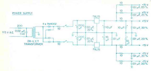
Fig. 6--Schematic diagram of the power supply. Note separate power feeds for
each channel, to reduce crosstalk.
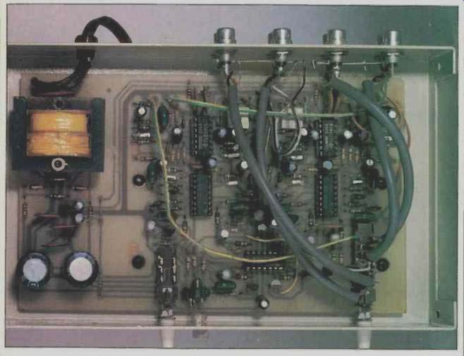
Fig. 7--Interior of P-522 noise-reduction unit, showing parts layout.
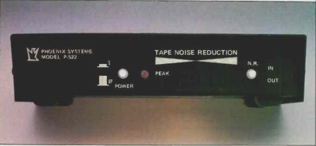
Fig. 8--Exterior of the completed unit.
Building the P-522
Schematic diagrams for the P-522's compressor, expander, and power supply sections are shown in Figs. 4, 5 and 6, respectively. While I recommend use of the p.c. board I've made available (see Parts List), you should be able to realize acceptable performance with other construction techniques. Do try to follow the layout in the photo (Fig. 7) as closely as you can, especially the grounding scheme. Use care when substituting parts; wider-tolerance parts can affect frequency response and dynamic tracking errors.
Substituting tighter-tolerance parts won't hurt anything but your pocket book.
========================
(adapted from Audio magazine, Feb. 1985)
= = = =
Also see:
Noise Reduction--Side Benefits & Side Effects (Apr. 1983)
The DNR Noise Reducer: How it Works and How to Build it. (Feb. 1985)