by Ken Kantor--Ken Kantor is Vice President, Technology, for NHT loudspeakers in Benicia, California.
If I were to give you 1,000-to-1 odds on a bet, you probably wouldn't take me up on it; it's quite a long shot. And designing something that can work over a range of 1,000 to 1 is a long shot, too: a motorcycle that can stay balanced at 1 mph and then zoom effortlessly to 1,000 mph, for example, or a pair of socks that will fit a 6-foot man, a small child, or a flea. Clearly, it's not easy for something to work over such a wide physical range. Yet that is exactly what a loud speaker designer who's seeking a frequency range of 20 Hz to 20 kHz is trying to do: build a device that can massage the air in long, slow strokes and vibrate it 1,000 times faster, all at the same instant. If truth be told, it can barely be done at all. That's one reason why speakers remain the weakest link in an increasingly accurate audio chain.
To ease the task, more often than not speaker designers decide that reproducing anything even close to the full range of audio frequencies requires two or more dedicated drivers, each assigned to a specific frequency range.
A 20-Hz tone has a wavelength in air of roughly 50 feet; even a tone as high as 100 Hz has a 10-foot wavelength. Thus, the kind of transducer, or driver, that will best radiate these long wavelengths must have a large surface area (so it will be relatively heavy) and a long excursion (because it must pump lots of air). By contrast, a 10-kHz tone's wavelength is just over an inch, and 20 kHz is half that; the radiation of high frequencies thus requires a very nimble, lightweight transducer that can move rapidly and accurately. Moreover, the diaphragm must be small to avoid directional beaming of very high frequencies. The intrinsic contradictions in these design goals are obvious.
For the speaker designer, the decision to use multiple drivers is not one to be taken lightly. When you split up the audio spectrum before it reaches the loud speaker or divide it up inside the speaker, it must be recombined in the air, which can cause interference between sound waves and other aberrations.
Consequently, not all speaker designers choose this route. Indeed, there are excellent, albeit expensive, speakers that use a single, full-range radiator, typically a flat or planar diaphragm. Such speakers' sound can be very coherent and subjectively transparent, but often at the sacrifice of dynamic range and with some limitation in frequency response at the upper and lower extremes. As a result, the vast majority of hi-fi speakers on the market today have multiple drivers. The advantages of a multi-driver speaker can be very compelling, and, with good engineering, the disadvantages can be minimized.
CROSSOVER TYPES
Now to the subject at hand: crossovers. A crossover is nothing more than an electrical circuit that splits the in coming audio signal into different frequency bands, each of which is sent to its own driver. Sometimes called a "net work," a crossover can be made up of a tangle of resistors, capacitors, and inductor coils, or it may be simple and elegant, with few component parts. A crossover is at the heart of virtually every multi-driver speaker, and there are two general types to consider: active and passive.
Active crossovers are electronic filters that reside in the signal chain between the preamp and power amp. They divide the line-level signal into different bands of frequencies and require each driver to have its own dedicated power amplifier.
Such crossovers are both precise and easily adjustable (if desired) but are fairly complex and rather costly to implement. On the other hand, having individual amplifiers for each driver enables those amps to be tailored to the power limits and response ranges of their loads. Active crossovers are commonly found in powered speakers, better-quality subwoofers, and in large, professional sound-reinforcement speaker systems.
By far the most common type of crossover used in hi-fi speakers is the passive network, which is usually housed within the speaker's en closure, either glued to the input terminals or mounted on its own p.c. board. This crossover type uses the frequency characteristics of passive components to create filters for example, capacitors that progressively block lower frequencies and let the highs pass through (high pass filters) or inductors (coils) that filter out highs and pass the lows (low-pass filters). Resistors-well, they resist them all. By using these parts in different combinations, the de signer can tailor frequency response and driver output level very precisely.
In a simple example of a passive crossover (Fig. 1), placing a capacitor in series with the tweeter of a two-way speaker will prevent the bass frequencies from reaching the tweeter. A 2-micro-farad (2-µF) capacitor might let only the highest frequencies in, while an 8-µF capacitor would extend the range of the tweeter down to ward the midrange.
(The 3.3-µF capacitor shown is a suitable value for this particular crossover design.) A similar selection of inductors in series with the woofer would block high frequencies. A large inductor-say, a coil of 6 millihenries (6 mH)-would aggressively attenuate upper frequencies more than a smaller inductor, such as the 1-mH inductor used on the woofer in Fig. 1. (Incidentally, the rate of attenuation of high or low frequencies by a filter, be it aggressive or gradual, is called the crossover slope.) To complete the crossover's design, we might add a resistor in series with the tweeter to better match its level to the less efficient woofer.
Although this seems simple enough in theory, a crossover's resistors, capacitors, and inductors interact electrically in mathematically complex ways, both among themselves and with each driver's frequency-varying impedance. The result is that almost no desired response curve is easy to achieve, yet almost anything is possible! All you need is a big pile of parts, a soldering iron, a lot of time, and an effective computer modeling program. That's it.
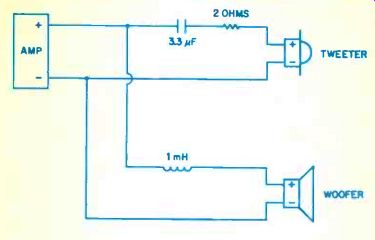
Fig. 1--A simple passive crossover network in a two-way speaker. The resistor
reduces the tweeter output level to match that of the less efficient woofer.
Take a look at Fig. 2, however, which compares the frequency response of a theoretical high-pass filter to the actual response for the simple high-pass network we attached to the tweeter in Fig. 1. And this doesn't even include the tweeter's acoustical behavior.
OBVIOUS AND UNSEEN CROSSOVER DUTIES
Most people are familiar in a general way with the role a crossover plays in dividing up a loudspeaker's frequency spectrum. Unquestionably, that is its single most important job, but it's not the only role it plays. Indeed, the crossover is thought by many contemporary designers to be as important as driver selection in determining a speaker's sound quality.
A crossover is, first and foremost, a kind of electrical filter, removing the unwanted signals from each driver and allowing the appropriate band of frequencies to pass through.
Midrange and treble tones are blocked, and the remaining bass frequencies are sent to the woofer; bass and treble are excised from the midrange path; and bass and midrange frequencies are kept out of the tweeter. Not only is the cross over dividing up the spectrum appropriately, but unwanted frequencies-those that could damage a particular driver or cause it to distort-are also tamed.
Not long ago, this job of allocating frequency bands to their appropriate drivers was all that crossovers were considered good at doing. Designers sought to achieve crossover responses that looked like textbook filters, i.e., with flat passbands and simple, steady rolloffs. It was assumed that if the crossover did the best job it could and the driver did the best job it could, then their combined frequency response would be optimal. In fact, that seldom occurred.
With computer simulation increasingly used in loudspeaker development, it be came possible to predict and optimize the electrical and acoustical behavior of speakers more accurately and in more detail. As this approach evolved, it became obvious that a crossover network's electrical behavior could be tailored to complement a particular driver's acoustical response, at least to some extent. So today, engineers no longer aim for a theoretically perfect cross over response and ignore the driver's acoustical behavior. Instead, modern crossovers are designed with synergy between their electrical properties and drivers' acoustical characteristics. Thus, a speaker's total response is the result of the crossover's electrical traits and the drivers' natural acoustical responses. If, for example, a woofer excels in deep bass output but its upper-bass response sags a little, a crossover can be designed to correct the woofer's acoustical response. Typically, a computer does the grunt work of picking a crossover's general topology-the type of parts and roughly what values are required for each. After that, it's time to build it, measure the response, and listen.
EQ IN DISGUISE
Okay, so you got the hint. The cross over can be an equalizer in disguise. If you are alarmed that an equalizer has crept into what you thought was your purist high-end system, well, you're right. Offhand, I can't think of a multidriver speaker less than a decade old that wasn't designed this way.
It's unavoidable. Any way you try to do it, the crossover's electrical behavior is going to affect the driver's acoustical response.
Why not be smart about it? Even after the drivers are integrated as well as possible, the final stage of any loud speaker development program is always a period of fine-tuning. No matter how care fully a system is planned on paper, its real-world performance requires a fair amount of tweaking, by ear and by microphone.
This is often called "voicing" or "balancing" the system. How is this final tweaking done? Drivers are almost impossible to modify quickly and repeatably. Moreover, a designer doesn't necessarily know if a change he's made in the lab will be carried over to the production line in the driver factory. And the enclosures take too much time to adjust once they are built; they are certainly not suited to the back-and-forth listening, five-changes-an-hour game. But the crossover is. Changing electrical parts is easy and predictable; the designer can even put a switch on the network to readily compare and decide between options.
So far, we've covered how crossovers slice up the audio spectrum to allocate chunks of it to multiple drivers, how they work electrically with the drivers to help the designer obtain a desired response, and how they are used in the final voicing of the finished system. But crossovers have one additional role that is critical to a speaker's final performance. The crossover's electrical circuits can modify signal delay and phase of the sound in each band so that the drivers' acoustical outputs will combine correctly in the listening room. By judiciously manipulating crossover phase response and properly selecting driver sizes and crossover points, the designer can alter a speaker's radiation pattern.
Thus, he can control to some extent such perceptually important factors as imaging and direct-versus-reverberant spectral response.

Fig. 2--Frequency response of a theoretical high-pass crossover, and of the
actual high-pass filter in Fig. 1 with the tweeter connected.
CROSSOVER POINTS
Now that we've covered the point of crossovers, let's move on to the crossover point. As you may know, this is the specific frequency at which the musical spectrum is split between drivers. Normally, it is stated as the frequency that is-3 dB (half the power output) for each of the two drivers in question, so that in theory, the two drivers' outputs will sum to produce flat response in the region where they overlap.
What you may not know is that published crossover frequencies are usually only vague approximations. With an actual loudspeaker, stating a precise crossover point tends to involve quite a bit of guess work. Real-world filter responses zig and zag, and the frequency that is -3 dB for the midrange low-pass filter might fall far from the -3 dB point of the tweeter's high-pass.
Combining the drivers' acoustical responses makes this even more complex, since response overlap will vary with the drivers' individual locations on the speaker baffle as well as with listener position. Experienced designers know that the effective response of the crossover, including the crossover points and slopes, is a combined function of the crossover network's electrical response and the drivers' acoustical response.
So designers work to make the system perform properly, then pick a frequency that seems like a reasonable approximation of the effective crossover point to list in the owner's manual or spec sheet. Nevertheless, the published crossover points can be informative. For example, pushing them down can be advantageous sonically, as lower crossover frequencies make wavelengths in the transition region longer and thus less likely to suffer from off-axis aberrations. I like to see a midrange or mid/woofer cross over to the tweeter in the vicinity of 2.5 to 3.5 kHz. A transition from midrange to woofer ideally should be at 250 Hz or be low, and from woofer to a true subwoofer at about half that frequency. Avoiding crossovers in the range from 300 Hz to 2 kHz is a good idea, because the ear is very sensitive to anomalies in this region, especially on voice reproduction. On the other hand, greater power handling is obtained by pushing crossover points up wards. This tends to direct more energy to the larger, more robust drivers. In a system optimized for output power rather than refined sound quality, you will probably find higher crossover frequencies than my choices. Bear in mind that these opinions are generalizations.
Every situation is a bit different, and there aren't even any standards for measuring and specifying crossover points.
SLIPPERY SLOPES
The second important specification for a crossover is its slope. This parameter, expressed in decibels per octave, indicates how rapid the cutoff is beyond the specified cross over frequency, i.e., how quickly the response is attenuated beyond the crossover point. Typically, the slope is described as first order (6 dB per octave), second order (12 dB per octave), and so forth.
Higher-order crossovers, which have steeper slopes, will improve power handling and reduce driver overlap, yielding cleaner polar response. Any driver misbehavior at frequency extremes is also cleaned up. Lower-order crossovers produce more gradual slopes and better transient response. Choose your poison--depending on philosophy, system goals, and driver quality.
Some designers are convinced that speakers with first-order crossovers offer sonic benefits that outweigh associated problems with radiation pattern and driver overlap, even though true first-order response is maintained only at frequencies near the crossover point. Other designers espouse very high-order networks and intentionally place crossover coils so that they will interact with each other and thereby achieve ultra-steep slopes, similar to those of tuner IF filters.
Just as with crossover points, however, slopes can be difficult to define accurately. Slope changes with frequency, as a result of the network's interaction with both a driver's impedance and its acoustical response. Many novice designers develop crossovers they believe are, say, first order, only to discover that they actually behave more like second- or third-order systems because of the acoustical slopes of the driver responses. Similarly, a slope may start off quickly yet not provide as much attenuation as expected far from the cutoff point. Fashions come and go, and opinions are often polarized, but over the years, no one approach has proved universally superior in terms of sound quality.
Odd-numbered crossover orders-first, third, fifth, and so on offer the theoretical benefit of correct, in-phase summation of two drivers' output at the transition frequency. But things in the real world are not so cut and dried. For example, because drivers are located at different positions on the speaker baffle, their outputs can never blend perfectly at all listener locations.
The resulting spatial pattern of energy peaks and nulls is called lobing.
One partial solution is to place drivers as close together as possible on the speaker baffle-particularly at high-frequency crossover points, where wavelengths are short. Another is to apply more sophisticated filters to the signal, which compensate for the aforementioned acoustical anomalies.
Easily the most well-known advanced crossover technique is the Linkwitz-Riley approach. This method is a means of calculating crossover filter response to optimize the summation of two drivers' on-axis acoustical output while minimizing off-axis errors. Here is Siegfried Linkwitz, of Audio Artistry, Inc., on crossover design:
In the '70s, it was common practice to place tweeter, midrange and woofer drivers at various locations on the front panel of a loudspeaker.
When I asked a speaker manufacturer how they came up with their driver arrangement, I was told that it was based on what sounded best. This somewhat ambiguous design practice led me to investigate the influence of driver positioning and cross over circuitry upon sound radiation.
In collaboration with my colleague, Russ Riley of Hewlett-Packard, I eventually came up with the now well-known Linkwitz-Riley cross over. Up to this time, the influence of driver placement and crossover-circuit selection upon the polar radiation pattern of a loudspeaker had not been appreciated.
When you have, for example, a two-way speaker, then there is always a frequency region where you have sound coming to you both from the tweeter and the woofer. Depending upon your listening position, your distance from the tweeter might be different from the distance to the woofer. Such difference causes a relative phase shift between the acoustic waves coming to you from the two drivers and affects how well the two waves add or cancel. In addition, the electrical crossover network introduces phase shift of the amplifier signal going to each driver. Correspondingly, there are also wave cancellations, which could occur at angles not far from the listening axis if the driver spacing is large.
We were looking for a crossover filter function that would give the maximum addition of sound waves from the two drivers when listened to on-axis and where the output would never be larger at any other angle.
Linkwitz's comments touch on many fundamentals of modern crossover design. The art and science of multiway loudspeaker design has progressed far beyond a simplistic division of lows, mids, and highs.
Designers must consider both on-and off-axis response if a speaker is to sound properly neutral, which is not a trivial balancing act. Factor in the usual requirements for great stereo imaging, high power handling, and a broad sweet spot, and you begin to see just how crucial a speaker crossover design is in deter mining the sound you hear.
===============
A CROSSOVER--Case Study
The NHT VT-1.2 is a three-way speaker developed for home theater use. Figure B1 shows the frequency responses c f its tweeter, one of its two mid ranges, its woofer, and the enclosure's port without any crossover in place. It is obvious that while each driver has a good response in its intended region of operation, the midrange driver and the woofer, in particular, have responses that deteriorate beyond their passbands. Also, there is much overlap of spectrum coverage between the drivers. Though quite typical of even the best drivers, these problems would lead to poor imaging, distortion and tonal coloration if they found their way into a finished product.
Figure B2 shows he electrical response of the crossover network developed for the VI-1.2. Crossover points are specifies at 120 Hz and 2.2 kHz, with a combination of first- end second-order electrical slopes These curves attenuate out-of-bald information, match the driver output level:, and correct for some minor deviations in driver frequency response (such as a slight hump in the midrange response just below 2 kHz). Not seen, but still important, are the high levels of distortion that would be present if low frequencies reached the midrange drivers and the tweeter.
Figure B3 illustrates the electrical circuit used to achieve the desired response curves. (Note t this system is bi-ampable, so it sets of input terminals are shown. Also, the woofer is wired out phase, to compensate acoustical for phase shifts introduced in various parts of the crossover network; the final output of all drivers will sum in phase.) For a good three-way loudspeaker, this is not a complex network. Among the advantages of working with good raw drivers, ones developed specifically for the application, is that a simpler crossover can be used. This not only saves cost, it also reduces the electrical impedance the audio signal encounters between the amplifier and the drivers, raising sensitivity and improving transient-response damping.
Figure B4 shows the VT-1.2's total system frequency response, measured at 1 meter, in a room.
Perfect? No way. But it's a far cry tom the raw driver responses, thanks to the crossover.
--KK.
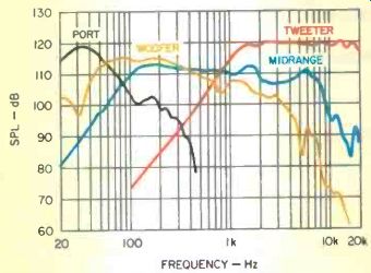
Fig. B1--Near-field frequency responses of the NHT VT-1.2's port and drivers without any cross-over in place.
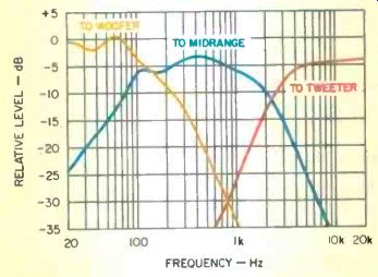
Fig. B2--Electrical response of the crossover net work designed for the VT-1.2.
The speaker's cross over points are specified at 120 Hz and 2.2 kHz, with
first- and second-order electrical slopes, respectively.
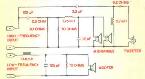
Fig.
B3--Electrical circuit used in the VT-1.2's crossover to achieve the desired
frequency response. The speaker is bi-ampable, so two sets of input terminals
are shown.
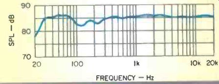
Fig. B4--Total system frequency response of the VT-1.2 speaker, measured
at 1 meter in a room.
(adapted from Audio magazine, Feb. 1997)
= = = =