MANUFACTURER'S SPECIFICATIONS:
Tuner Section: IHF Sensitivity: 1.8 µV. Image Rejection: over 45 dB Stereo FM Separation: over 38 dB @ 1 kHz. AM Sensitivity: 10 µV for 20 dB S/N.
Amplifier Section: Power Output: 50 watts total IHF Music Power, 8-ohm load. Power Bandwidth: 20 to 20,000 Hz. Frequency Response: 15 to 50,000 Hz ±1 dB. Tone Control Range: ±15 dB at 50 Hz (Bass) and 10 kHz (Treble). THD: Less than 0.8% at rated output; less than 0.3% at 10 watts, less than 0.2% at 0.5 watts. Input Sensitivity: Mag Phono: 2.8 mV; Tape Head: 1.8 mV; AUX: 1.2V into 250K ohm load. Hum and Noise: Tape Head:-55 dB; Mag Phono:-60 dB; AUX:-65 dB.
General: Dimensions: 15 1/4" W x 12 3/4" D x 4 3/4" H.
Weight: 17.7 lbs.
Price: $189.95.
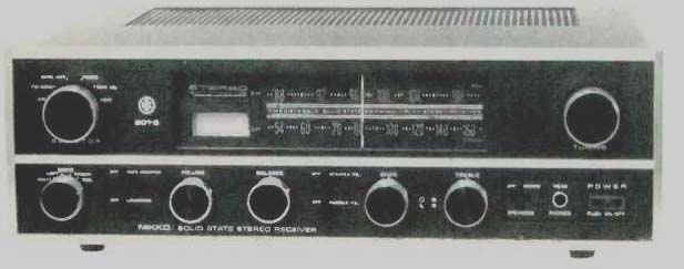
Fig. 1- Nikko Sta-501S stereo FM/AM Receiver
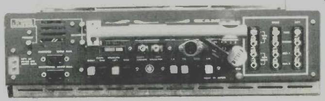
Fig. 2. Rear Panel View
For an integrated receiver in the "under $200.00" price class, this Nikko receiver offers a full measure of amplifier power and specifications, but somewhat less performance and quality in the FM tuner section. Getting away from the traditional brass or gold look of so many of its competitors, Nikko offers a front panel in matte black and silver trim, with highly legible white control markings. The dial-scale area offers only about five inches of actual calibration for AM and FM frequencies, the rest of the opening being devoted to a large tuning meter surmounted by a long red stereo-indicator lamp. No logging scale is provided. The balance of the upper half of the panel consists of two huge knobs-one for tuning (coupled to a very minimal flywheel which, however worked very well) , the other for signal-source selection.
The lower portion of the panel contains, starting at the left, a mode switch for listening to right or left channels through both speakers and for stereo or stereo-reverse operation.
Next come two slide switches for tape monitor and loudness-contour insertion. Volume and balance controls are next, followed by scratch-and rumble filter slide switches. Bass and treble controls are of the dual-clutch-action type, enabling individual channel tonal compensation, if desired. A remote-speaker switch is next, so arranged that the main speakers are always operative unless a pair of headphones is plugged into the adjacent headphone jack. The power on-off switch is of the push-push type and becomes illuminated in bright red when power is applied to the receiver.
A photo of the front of the receiver is shown in Fig. 1 and, although there seem to be no more controls than on similar products, the panel does tend to look a little crowded although this is a purely personal view.
Surprisingly, the rear panel, shown pictorially in Fig. 2, is a model of thoughtful organization. No less than three circuit-breaker buttons are provided, for instant re-set in the event of power-supply or speaker-line overload. One switched and one unswitched a.c. receptacle are followed by spring-loaded speaker-connection terminals. These terminals accept the stripped ends of speaker leads with no wrapping or tightening of screws required. When the terminal head is depressed, a small hole appears into which the end of the exposed wire is inserted. Releasing the terminal head results in a tight and permanent connection with virtually no possibility of shorted speaker leads from then on.
FM and AM antenna terminals are similarly constructed, although for some reason the remote-speaker connection is made by means of phono tip plugs, which would have to be soldered to the speaker cables in question. A DIN tape-recorder socket in addition to the usual input jacks and a ground terminal completes the rear panel layout. The built-in AM antenna can be pivoted 90 degrees for best AM reception, a very welcome innovation for those who must position the equipment on the "wrong" wall.
Removal of the metal cabinet in which the STA-5018 is supplied discloses a rather crowded parts layout, with most components mounted on p.c. boards of varying size and description. Interestingly, the metal cabinet has a permanent inter-lock power cord attached to it, which detaches from the unit whenever the cabinet is removed to prevent accidental shock when servicing the unit. This technique is often used with "hot chassis" designs, in which one side of the line voltage is electrically connected to the chassis itself. This is definitely not the case here, but because of exposed a.c. voltage points within the set, the designers thought best to provide this protection. An "inner" view of the chassis layout is shown in Fig. 3.
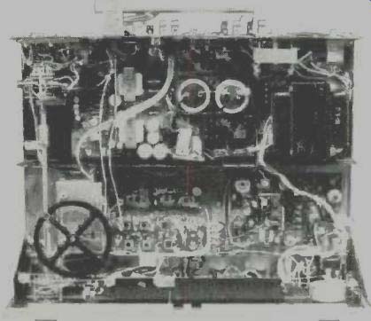
Fig. 3--Internal component layout.
Measurements
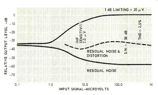
Fig. 4--FM characteristics.
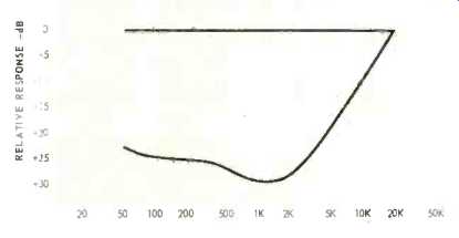
Fig. 5--Stereo separation.
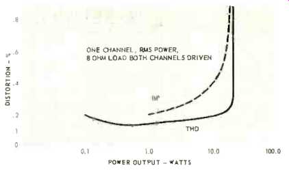
Fig. 6-THD and IM characteristics.
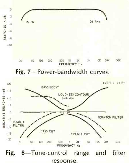
Fig. 7--Power-bandwidth curves.
Fig. 8--Tone-control range and filter response.
The significant FM performance measurements of the STA-501S are shown graphically in Fig. 4. Note that the IHF sensitivity which we measured was 7µV, Ultimate signal to noise ratio was 58 dB, while THD in mono was 2.3% for full modulation, measured at 1000 µV. In stereo, this figure increased to 2.8%. Signal strength meter readings were found to be quite meaningful on this set, unlike most such meters which reach full scale at only a few microvolts of input signal and are therefore of little use in gauging signal strength. In the case of this unit, a reading of 80% of full scale was reached with 1000 µV signal input.
Stereo FM separation is plotted in Fig. 5 and is considered acceptable at low and mid frequencies, though it does fall off rather sharply above 5 kHz.
Although no statement is made by the manufacturer regarding rms power output capability, we measured 1% THD at an output of 20 watts rms per channel with both channels driven. This seems reasonable in view of the music power figure of 25 watts per channel listed by the manufacturer. Of greater significance than the high power-output figures is the fact that there is little tendency for the distortion to rise at low power outputs either--a malady often found in today's less expensive equipment. At no power output below 15 watts did the THD exceed 0.2%. Results of these measurements are plotted in Fig. 6, along with IM distortion measurements which reached 1.0% at an output power of 17.5 watts, rms.
Power bandwidth, based upon an rms power output of 20 watts, was found to agree nicely with manufacturer's claims, as shown in Fig. 7.
Figure 8 is a graphic plot of tone-control action, loudness compensation and high- and low-frequency filters. The loudness-compensation curve was plotted at-30 dB from full volume settings and conforms well to accepted practice in this feature. The filters, on the other hand, are very gentle, since they are of the 6-dB-per-octave type and do not significantly cut response within the passband desired.
Hum and noise in the phono position was-60 dB, as claimed, while hum and noise in tape head and aux positions exceeded published ratings, measuring 60 and 72 dB respectively.
Listening Tests
As might be expected, the FM portion of this receiver did not quite come up to the more expensive models, this fact was confirmed when we tried to use the dipole supplied with the receiver. Whereas we normally are able to get between 35 and 40 acceptable signals in our near-city suburban location, this receiver picked up some 32 signals, of which about 12 were in acceptably noise-free stereo. With the application of a good outdoor antenna, the number of acceptable stations was increased to 40, of which 15 were broadcasting in stereo FM. One obvious deficiency noted was the rather poor limiting exhibited by this unit.
"1 dB" limiting, as noted in Fig. 4, is achieved at a signal input level of about 30 µV. As a result, weak stations were received at considerably lower audio level than stronger stations, necessitating constant readjustment of the volume control when tuning from station to station. With the outdoor antenna in use, however, this condition was minimized, since nearly every signal received was greater than 30 µV. Gain and power output of the amplifier are such that the unit was capable of delivering ample power to a pair of inefficient air-suspension speakers in our medium-sized listening area. The addition of a second pair of speaker systems of similar construction, however, resulted in noticeable distortion when we tried to push the sound levels to what we consider "concert hall levels." If medium- or high-efficiency speaker systems were to be used, however, the STA-501 would be able to provide more than enough sound for just about anyone's listening tastes. Control action was smooth and effective and transient response was good. Levels, too, were correctly set, so that switching from phono to FM resulted in almost equal levels. AM, however, was a bit "heavy" sounding, and seemed constricted in bandwidth even beyond that normally expected of the AM section of a receiver. Sensitivity of AM was excellent, however, considering the minimal circuitry employed.
When one considers this receiver in terms of price, one cannot overlook the fact that not too long ago an integrated amplifier, at 20 watts per channel, used to cost as much as this entire receiver. For metropolitan-area installations where reasonably efficient speakers are to be used, the Nikko STA-5015 represents very good value for the price. Extended use did not disclose any undue heating of components, so that trouble-free service can be anticipated from this model.
As for the aesthetics, they are, after all, a matter of taste.
-----------------
(Audio magazine, Mar. 1970)
Also see:
Nikko Gamma I Stereo FM Tuner (Equip. Profile, May 1979)
Nikko Gamma 30 Tuner (Jan. 1987)
Nakamichi Model 730 Stereo FM Receiver (Dec. 1978)
= = = =