MANUFACTURER'S SPECIFICATIONS
FM TUNER SECTION:
IHF Sensitivity: 1.8µV. S/N: 65 dB. THD: (Mono), 0.4%; Stereo, 0.8%. Selectivity: 65 dB. Capture Ratio: 1.5 dB. IF Rejection: 90 dB. Image Rejection: 80 dB. Spurious Response Rejection: 90 dB. Stereo Separation: 36 dB @ 400 Hz.
AM TUNER SECTION:
IHF Sensitivity (Internal Antenna): 200p, V. Selectivity: 35 dB. S/N: 45 dB. Image Rejection: 60 dB. IF Rejection: 60 dB. Bandwidth (-6dB): 7 kHz.
AMPLIFIER SECTION:
Power Output: 60 watts per channel, Stereo Mode; 30 watts per channel, 4-channel mode, continuous power at 1 kHz.
Rated THD: 0.5%. Rated IM: 0.5%. Power Bandwidth: 10 Hz to 40 kHz. Frequency Response: High Level: 15Hz to 25kHz+ 1 dB. Damping Factor (8-ohms): 35. Input sensitivity: Phono 1 & 2, 2.5/4.5 mV; High Level, 250 mV; Microphone, 1 mV. Tape Output: 350 mV.
GENERAL SPECIFICATIONS:
Dimensions: 7 in. Fix 18 1/2 in. W x 17 1/2 in. D.
Power Requirements: 120 V 50/60 Hz.
Weight: 44 lbs.
Price (Includes walnut enclosure): $499.90.
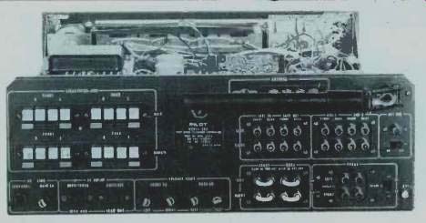
Fig. 1--Rear panel layout.
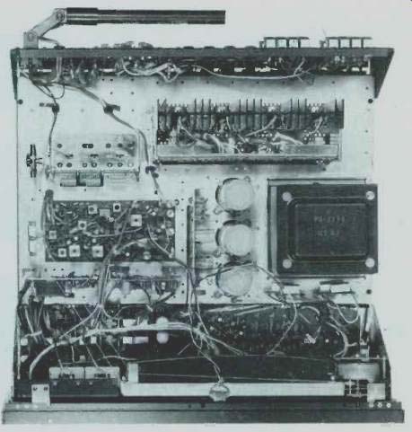
Fig. 2--Internal chassis layout.
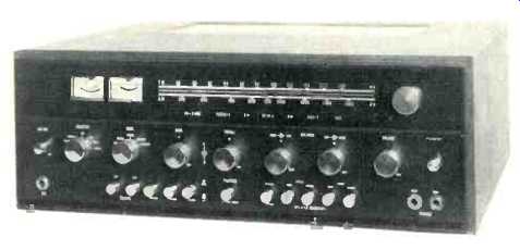
The Pilot 366 4-channel receiver is a large, imposing unit, laden with control features and control flexibility which will appeal to the audiophile who wants quadraphonic sound mixed in with a bit of a recording facility. We're referring to the fact that in addition to the features you would expect, the Model 366 has a pair of microphone inputs located 'right on the front panel, above which is a dual level control knob which enables the user to "mix" mic or instrument inputs together with any other program source. Unfortunately, the mixing control affects both mic inputs, thereby limiting its flexibility. As for the front panel, it is black epoxy-coated aluminum, screened with white letters of good, readable size and equipped with silver colored knobs and pushbuttons. Major front panel controls include a SELECTOR switch (with two PHONO) and two AUX positions plus AM and FM), a five-position mode switch (Mono, STEREO, MATRIX-4, SQ and DISCRETE), separately operated dual-concentric clutch type BASS and TREBLE controls, a pair of BALANCE controls (front-back and left-right), also clutch operated for individual channel balance, and a master VOLUME control. There are twelve push buttons for secondary control functions such as LOW and HIGH FILTERS. TAPE MONITOR. LOUD NESS, MUTE. speaker NORMAL-REVERSE (Which affects rear speakers only), speaker selector switches for MAIN and REMOTE (duplicated for stereo power mode or quadraphonic power mode) and a POWER on/off push button. The previously referred to MIC level control and input jacks are located at the lower left of the panel while a matching pair of PHONE jacks are symmetrically located at lower right. Upon application of power, the upper portion of the panel is illuminated either by a single word, denoting selector switch position or, in the case of AM or FM selection, by a green dial scale and a yellow pointer tip. At the left of this portion of the dial are two meters, a center-of-channel meter which is illuminated only when FM listening is selected and a signal strength meter, illuminated during AM listening. This area of the panel also has illuminated lights to tell the user whether the mode switch is in mono, stereo or 4-channel settings. In our view, the separate buttons for two-speaker and four-speaker mode (with "double power available in stereo") is a bit confusing, though not dangerous, for Pilot's instruction manual cautions against pushing, say, a "main speaker" button for both 2-channel and 4-channel operation at the same time! These buttons would have been better off combined as a single rotary selector switch, much as other manufacturers of "strapped" four-channel receivers have done.
Figure 1 is a view of the rear panel layout of this receiver.
Sixteen black and red color coded spring loaded terminals make speaker connections simple. Stripped wire ends are merely inserted in holes that are accessible when each button is depressed and are firmly retained in place when the button is released-no twisting or turning of screws required. In addition to screw-type antenna terminals for 300 ohm FM and external AM antennas, there is provision for a coaxial connector for 75 ohm FM transmission lines. Each pair of phono inputs is accompanied by a slide switch which varies phono input sensitivity from 2.5 mV to 4.5 mV. Jumpers installed in four pairs of PHONO jacks permit separation of each preamplifier channel from its associated main amplifier section. Sixteen additional phono jacks take care of AUX 1, AUX 2, TAPE IN and TAPE OUT circuits. (It's amazing how the number of jacks multiplies when you double everything for four-channel applications!) An FM detector output jack is located at the extreme right of the rear panel, and there is a switch which turns off this facility (for the next couple of years until discrete FM broadcasting begins) and we are at a loss to understand why this jack must be disconnected when not used, since it is simply a connection point to the FM detector output. In fact, we could detect no difference in FM performance with the switch "on" or "off." Four speaker line fuses, a power line fuse, a switched and un switched convenience a.c. receptacle, a ground terminal and the usual ferrite bar AM antenna complete the rear panel arrangement.
A view of the internal layout of the Pilot 366 chassis (Fig. 2) discloses that it is constructed of individual p.c. board modules, although there seems to be an inordinate amount of inter-wiring required. The sealed and shielded front-end utilizes a four section variable capacitor for FM and a three section unit for AM. Three dual-gate FET's are used in the circuitry of the FM front-end. The relatively small i.f.-MPX module contains three IC's in the FM i.f. section as well as ceramic filters. An IC does most of the job of stereo decoding as well, while the AM circuitry consists of bi-polar transistor circuits. Preamplifier. voltage amplifier and tone control stages are constructed using conventional circuitry and separate transistors rather than IC's while NPN power output transistors are powered by dual positive and negative 33 volt supplies, eliminating the need for coupling capacitors between outputs and speakers. The SQ decoder module employs minimal phase shift networks, which are switched out of the circuit when the MATRIX-4 decode position is selected. This setting is recommended by Pilot for listening to conventional stereo records and extracts ambience or out-of-phase information in the now familiar way. A novel additional circuit is a locally-generated 1 kHz oscillator which is used as a test signal to balance sound levels from all four speakers. A central PILOTONE button, not previously mentioned, is located on the front panel for this purpose. This test signal presumes that program sources as well as internal amplification in the receiver, are equal, which may or may not be the case.
Power supply voltage is obtained by means of a bridge rectifier arrangement with 6800 mfd capacitors used for primary filtering of both negative and positive output stage voltages.
Each basic amplifier section has a differential amplifier stage as an input and coupling is direct from this stage to output transistors.
Tuner Section Measurements
IHF sensitivity in FM, as measured on our sample, was exactly 1.8 µV as claimed. A 50 dB S/N ratio was obtained with an input signal of only 3µV, but ultimate S/N was 63 dB in mono, as opposed to the 65 dB specified. Both mono and stereo THD were considerably better than claimed by the manufacturer, measuring 0.2% and 0.4% respectively, at mid frequencies of audio modulation. Results of these measurements are plotted in Fig. 3. Muting and stereo switching threshold occurred at an input signal strength of about 10 microvolts. For stereo reception, ultimate S/N was 63 dB, a value obtained for all input levels above about 100 microvolts.
Stereo FM separation and distortion versus frequency in FM are plotted in Fig. 4. At mid-band frequencies, separation exceeded manufacturer's claims by roughly 3 dB, measuring 39 dB. Separation decreases gradually to about 30 dB at 100 Hz and 27 dB at 10 kHz-figures which are more than adequate for this parameter. Mono THD remains less than 0.5% for all frequencies from 50 Hz to 4 kHz rising to an acceptable 0.7% at high audio frequencies. Stereo THD hovers around the 0.5% mark until "beats" appear at higher frequencies, resulting in a spurious output reading of about 2.3% at 5 kHz. Selectivity measured 65 dB as claimed, while capture ratio fell a bit short of published claims, measuring 1.8 dB. Spurious response rejection measured 93 dB, a bit better than claimed, while i.f. and image rejection conformed almost exactly with Pilot's published specifications. The AM section proved to be quite good, with sensitivity reading of 150 u V as opposed to the 200 u V claimed. Using an external dummy antenna, sensitivity was just under 20 microvolts, while selectivity measured 38 dB..
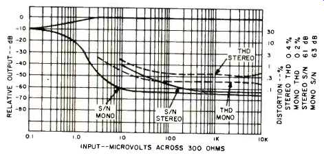
Fig. 3-FM quieting and distortion characteristics.
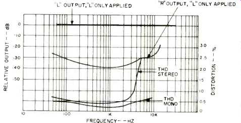
Fig. 4-Separation and distortion vs. frequency.
Amplifier Measurements
In the four-channel mode, maximum continuous power output obtained for rated THD (0.5%) equaled 28 watts per channel. At the rated value of 30 watts per channel, THD was 0.7%. IM distortion measured 0.8% at rated output under the same conditions. Distortion at lower power levels remained at or near 0.5%, while IM decreased to roughly 0.4% for lower power output levels. These values are plotted on a continuous basis in Fig. 5. It should be noted that no plot is made for the strapped condition (stereo operation), however, results were essentially the same using a reference of 60 watts continuous power per channel. All readings were taken with all channels driven into 8 ohm loads.
Power bandwidth, plotted in Fig. 6, extends from 10 Hz to 40 kHz as claimed. It should be noted however that the 0 reference point in this plot is 30 watts per channel and since actual power output for rated THD is slightly lower than 30 watts, mid-band points on the curve also fall below the 0 dB reference. If Pilot had chosen to rate the unit more conservatively (say, 25 watts per channel), power bandwidth on that basis would have extended somewhat beyond the limits of 10 Hz and 40 kHz.
If the amplifier section of the Model 366 is driven to 30 watts at 20 Hz, THD rises to about 2%, as shown in Fig. 7.
At half power, however, distortion remains fairly constant over the entire audio spectrum. Action of preamplifier section controls is plotted in Fig. 8. Bass boost action is a bit extreme and this control should therefore be used in moderation to avoid overloading the amplifier at low frequencies. The low frequency filter has a slope of 12 dB per octave, while the high-cut filter behaves much like the treble cut control, at a slope of only 6 dB per octave. Loudness contour (measured at 30 dB below maximum volume control setting) is typical of this circuit and Pilot's designers have chosen to emphasize treble as well as bass when the loudness control is activated, though the treble boost is more moderate as it should be.
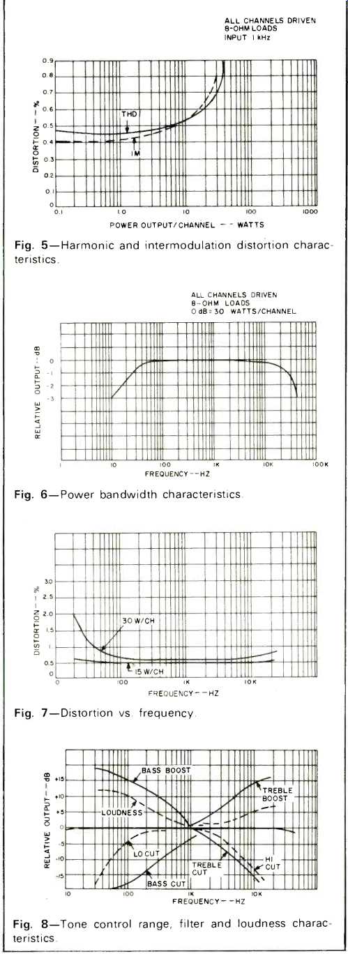
Fig. 5--Harmonic and intermodulation distortion characteristics.
Fig. 6--Power bandwidth characteristics.
Fig. 7--Distortion vs. frequency.
Fig. 8--Tone control range, filter and loudness characteristics.
Listening Tests
In the course of listening to the Pilot 366. we discovered and used a couple of additional features which we had not noticed up to that point. For example. the illuminated pointer, we found, changes color from yellow light to red light when a station is precisely tuned in on FM. It takes a fairly strong signal to make the light color change, however, and under those circumstances, the "window" of color change is fairly broad and we still preferred setting accurate tuning by means of the center-of-channel meter. Still, it's an interesting feature. We also found that the MATRIX-4 setting of the mode switch worked well with some stereo discs but worked to our satisfaction even on some quadraphonic-encoded discs--sometimes better than when the same discs were played in the SQ position.
The built in SQ decoder circuit in the Pilot 366 is the simple non-logic type and in certain instances this type of SQ decoding results in some ambiguities, particularly when a "stage front and center" soloist is involved in the recorded performance. It was with such recordings that we found the MATRIX-4 setting to be more effective than the SQ setting.
Power output of the receiver was adequate for medium-low efficiency speakers in the four-channel mode. Power capability seemed noticeably better when we hooked up only a pair of stereo speakers and treated the receiver as a two-channel unit. We're well aware of the fact that the difference in power output under those circumstances is only 3 dB and that it should have been "barely noticeable" but we can only report on what we heard. Perhaps that three dB made the difference between bass distortion and clean bass at the levels we used in our tests.
For those interested in adding CD-4 demodulator equipment to this receiver, the fact that there are a pair of AUX inputs available in a convenience and permits you to hook up a CD 4 demodulator without having to disconnect your tape recorder or other high level program source.
FM reception was acceptable, and we were favorably impressed with the positive action of the muting circuits. There was no audible transition noise as stations were approached when the muting circuit was in use. The threshold point (10 microvolts) chosen by Pilot seemed right for a tuner of this sensitivity as well, though we were able to listen to three or four stations with acceptable quieting with the mute defeated that would have otherwise not been received.
Under $500 is what you would normally expect to pay for a stereo receiver with 60 watt per channel capability. The fact that Pilot is able to offer that "dollars per watt" ratio and quadraphonic capability with built in decoding facilities as well makes the Pilot 366 worth a second look.
-Leonard Feldman
(Adapted from : Audio magazine, Mar. 1974)
Also see:
Pioneer Model SX-1980 Stereo AM/FM Receiver (Equip. Profile, Sept. 1978)
= = = =