There are several reception problems that can occur whether you have the crudest
antenna system possible or one of the best. In fact, the first problem to be
discussed, overload, may actually be aggravated by a good antenna!
Overload
This is the result of too much signal for the tuner to handle under certain reception conditions. In the competition for the consumer dollar, tuner manufacturers engage in a "numbers race" in regard to tuner sensitivity.
This is not their fault, since consumers feel a tuner is inferior unless it boasts a sensitivity figure below two microvolts. Yet, over 90 percent of the purchasers of such tuners do not need this much sensitivity. In many cases, this high sensitivity works against them when a tuner is operated in a high signal metropolitan environment. This is because the design techniques for high sensitivity and those for low cross-modulation susceptibility (resistance to overload) are quite dissimilar.
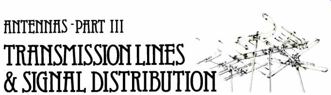
---Fig. 1 RMS CA-1121 barrel attenuator.
When local stations are the ones you want to hear, overload is easily solved by inserting an attenuator in the cable, preferably near the tuner input. The RMS Electronics CA -1121-20 barrel attenuator (Fig. 1) is ideal, as its fittings permit it to be installed without an extra cable. The amount of attenuation required depends on the signal level, although 20 dB is good as a starter and will do for most cases. An additional 20-dB attenuator can be connected for the rare case where the signal level is enormous and the tuner particularly susceptible to overload.
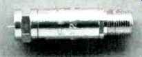
If you want to hear very weak (distant) stations and you are located very close fo an extremely powerful station, attenuation cannot be used. If the powerful local station is more than 5 MHz away from the desired station in frequency, a simple tunable rejection filter can be used. The Jerrold RFT-300 (Fig. 2) and Radio Shack 15-1145 are very low priced filters that produce over 22-dB attenuation at the trap center frequency. These devices are installed in parallel with the 300-ohm antenna terminals. For installations using cable, disconnect the cable from the tuner's 75-ohm input and connect the cable to the 300-ohm input through a balun. The rejection filter is then connected across the tuner's 300-ohm input terminals in parallel with the balun.
--- Fig. 2 - Jerrold RFT-300 notch filter.
If the weak distant station and powerful local station are very close in frequency, the trap cannot be used. (It is not selective enough to attenuate the strong station without also attenuating the weak one.) The only recourse in this case is to use the directional properties of a high -gain, narrow-beamwidth antenna (on a rotator, of course) to null out the powerful local station while boosting the level of the weak distant station.
By careful positioning of the antenna via its rotator, you can reduce the pickup of the local station by 15-30 dB, depending on the null characteristics of your antenna. Hopefully this will reduce the local signal below the troublesome level.
CB Radio Interference
CB radio is the major cause of FM radio interference because of the number of CB transceivers in operation. With simple tuners, the interference mode is usually cross modulation (via front-end overload). A high-performance tuner may have stations near the upper edge of the FM band blacked out by 4th harmonic radiation at 108 MHz if the antenna of an ordinary CB transceiver is located next to the FM antenna. However, if an illegal power amplifier is used by the CBer, interference can occur even with considerable distance between the antennas.
An FM antenna will pick up the 4th harmonic of a CB signal as readily as it will pick up a 108 MHz FM signal.
Directionality is the only means of discriminating between the CB and FM signals, so an FM antenna with a high front -to -back ratio and deep side nulls is needed. The antenna is oriented to reject the CB harmonic and/or increase the FM signal. (Suitable antennas were mentioned in the first part of this series.) Best interference rejection occurs when the direction of the CB signal is at or near a right angle to the FM station; then the CB signal will disappear in the null typically occurring at 90° or 270° while the FM station is picked up at full strength.
Once radiated, CB harmonics cannot be eliminated other than by the antenna "trick" just described.
However, if you can locate the offending CB transmitter, the harmonic radiation may be eliminated at the source.
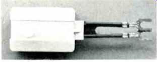
A good low-pass filter installed on the output of a CB transceiver will usually solve this problem. The Electronic Specialists FLCB-LP (Fig. 3 top) is inexpensive and installs directly on the transceiver output jack. It will provide about 50 -dB attenuation at 108 MHz.
The Channel Master 5272 (Fig. 3 bottom) is more expensive but was measured to have over 70-dB attenuation at 108 MHz in the author's tests.
This filter also produced incredibly high attenuation of the 2nd and 3rd CB harmonics (which may be ruining your TV reception!). A short jumper cable is required with this filter.
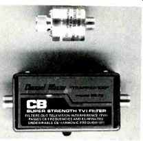
Harmonic energy escapes through the line cord of some transceivers and is radiated by the house wiring. A power -line filter installed between the transceiver's power cord and the a.c. outlet will prevent this. The Vidaire Electronics CF-5 (Fig. 4) is a low-cost filter that provides over 40 -dB attenuation to the 108 MHz harmonic. The Radio Shack 15-1106 will do likewise.
---Fig. 3 - CB low-pass filters; top, Electronic Specialists FLCB-LP; bottom;
Channel Master 5272.
CB radiation may be picked up on the FM transmission line rather than the antenna. If the FM twinlead passes close to a CB antenna, replace the FM receiver's twinlead (or even standard coax) with one of the foil -and -braid coaxial cables or foil-shielded twin-leads recommended in Part II. Because some CBers use illegal power amplifiers, sufficient fundamental (27 MHz) signal may squeeze through a low-cost FM receiver's input circuits to overload the r.f. stage. In this case, one of the filters specified in Table I of this part of the series should be installed. CB fundamental filters are available in a variety of styles and impedances. Most of them are inserted between the transmission line and the receiver input terminals, but the Jerrold CBT-300 and Radio Shack 15-1146 are notch filters that are simply connected across the receiver input terminals in parallel with the antenna leads or balun. (Except for the lack of a tuning knob, these notch filters look just like the Jerrold RFT -300 in Fig. 2.) Note that the RMS CA-2600F and Jerrold T-4040 (Fig. 5) are combination high-pass filters and baluns; they match coax to the ohm antenna terminals as well as filter. All of these filters did their job well in the author's tests and measurements.
If the FM stations have adequate signal strength, add attenuation to the transmission line with a 20 -dB barrel attenuator, such as the RMS Electronics CA-1121M-20 (Fig. 1). This device should be connected between the coaxial cable and the filter (a 75 -ohm input unit) or balun. This may reduce the combined level of the FM signal and interference below the level that causes cross -modulation. If the FM signal is not strong enough to do this, replace the existing FM antenna with one of the very high gain and directional models mentioned in Part I. The directionality will also improve the signal-to-noise ratio (specifically the FM signal-to-CB fundamental ratio). However, since this is an expensive step, it should only be tried if you are desperate (and wealthy).
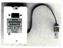
---Fig. 4-Vidaire CF -5 line filter.
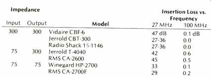
---Table 1: CB Fundamental Filters.
Electric Motor Interference
While FM receivers are supposed to be inherently noise immune, they do respond when the interference is strong enough. Receiver manufacturers acknowledge this fact via the impulse -noise suppression circuits that appear now and then in the more expensive models.
Fortunately, if the interference is strong enough to be picked up on a modern FM tuner, it means the noise [...]
Also see:
- What Kind of FM Antenna is Best for You? (Part 1) (Jan. 1978)
- Antennas Part II--Transmission Lines & Signal Distribution (Feb. 1978)
- Antennas Part V -- Special Antenna Techniques (Jan. 1979)
(Source: Audio magazine, Mar. 1978; M. J. Salvati )
= = = =