cont. from part 1
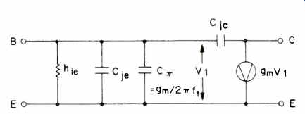
Fig. 9 Simplified transistor model.
Note that g_m, and thus C_pi, are proportional to collector current.
[...] discharge the capacitor by about 60 mV (as dictated by the exponential Ic vs. Vbe transistor law). Although this voltage seems small, we must realize that the capacitance is on the order of microfarads when the transistor current is on the order of amperes for typical power transistor f_t s in the range of 1 to 4 MHz. It can be shown that if we try to turn off the transistor by pulling a constant current out of the base, the collector current of the transistor will decrease at a reasonably constant rate; i.e. it will slew off at so many amperes per second. This is a direct result of the integrating action of the charge-storage capacitance. Specifically, the current slew rate is given by the simple expression:
ISR = 2 π f_t I_b, where I_b is the base current.
Now let's see how this phenomenon affects the performance of an output stage when program signals change quickly. In most amplifier designs, a very large current can be supplied by the drivers (usually emitter-followers) to turn on the output devices quickly in response to program demands. Unfortunately, the available turn-off current is limited to the amount of quiescent current flowing in the power transistor base-bleeder resistors (R5 and R6 in Fig. 4). There is thus a well-defined turn-off current slew rate associated with each of the output devices.
Suppose for the moment we are operating into a resistive load; the top transistor is "on" and the output voltage is positive but rapidly heading in a negative direction. The current into the load is decreasing rapidly; i.e., the rate-of change of the output current is highly negative. If this rate of-change exceeds the turn-off current slew rate for the top device, that device will go into current slew-rate limiting.
Under these conditions the transistor's current is no longer a function of the signal, and it thus represents a source of distortion. The bottom transistor will, of course, tend to conduct more heavily to make up the difference, but the distortion will not be completely removed. This extra current conduction on the part of both transistors is referred to as "common-mode conduction," and is also responsible for increased output stage power dissipation (sometimes dangerously so) at high frequencies.
Because the opposite transistor makes up for most of the deficiency of the device being turned off, this current slewing phenomenon does not manifest itself as visual voltage slew-rate limiting at the amplifier output.
To see how serious this problem can be, let's assume 1 MHz ft power transistors in Fig. 4. With about 8 mA of turnoff current available, the current slew rate for each device is about 0.05 A/uS, corresponding to a voltage time derivative of 0.4 V/uS into an 8-ohm load, or less than one watt at 20 kHz. Such an amplifier can thus be expected to generate substantial amounts of high-frequency intermodulation distortion at moderate power levels.
This problem can also be effectively dealt with, however. The most common solution is to use low-valued bleeder resistors (i.e., run the drivers fairly "hot") and faster output transistors. Assuming 4-MHz ft devices for the design in Fig. 7, where about 30 mA is available for turn-off, we have a turn-off current slew rate of 0.75 A/ uS, corresponding to a voltage time derivative of 6.0 V/uS into 8 ohms or 144 watts at 20 kHz.
The Case for A Large Feedback Factor
We've spent quite a bit of time so far examining many issues and arguments and are led to conclude that a large feedback factor and its attendant small open-loop bandwidth does not do any harm, given a design with the same gain crossover frequency as a low-feedback design. But what good does it do? Specifically, why should more feedback be applied at mid-band frequencies when the problem seems to be at high frequencies, and 20 to 30 dB at the high frequencies is probably sufficient given a fairly linear open loop amplifier? First, the weak but not unimportant argument: It costs nothing. In fact, in most designs it saves one or two resistors (R15 and R16 in Fig. 7). The more convincing argument rests on the fact that negative feedback reduces the percentage of output stage distortion components at a given frequency by the same factor that it reduces gain at that frequency. The Class AB output stage is a major contributor to open-loop nonlinearity in good designs, and local degeneration cannot significantly reduce its distortion. Only overall negative feedback does a good job there.
Suppose an open-loop amplifier is handling a 1-kHz sine wave input and second harmonic distortion is being produced at 2 kHz in the output stage. When feedback is applied, the 2-kHz distortion product percentage (for the same output level) will be reduced by the same degree that feedback reduces the amplifier's gain at 2 kHz. Since feedback factor is often a function of frequency, we must remember that the feedback factor at the frequency of the distortion component (not the fundamental) is what is important. This rule is independent of the phase shift around the feedback loop; in the extreme case of positive feedback, distortion percentages would be increased by the same factor that the gain increases at a given frequency.
Because of this action, the additional loop gain at mid- and low frequencies in the high-feedback designs contributes an important distortion reduction not so important for mid band harmonic distortion, which can be expected to be low anyway, but rather for mid-band intermodulation products which result from two or more high-frequency signal components involved in high-frequency intermodulation distortion.
Few people can be expected to hear the THD produced by signals much above 10 kHz (although THD is a good indicator of performance). Rather, it is the low-frequency inter modulation products which can detract from, say, a cymbal crash. These products, which may fall in the most sensitive portion of the audio spectrum and which may not be well masked by other sounds, will be further reduced by the additional low-frequency feedback. The additional 10 to 40 dB of feedback in these designs can thus improve the sound of the high frequencies even though the additional feedback only occurs at lower frequencies.
Distortion produced in earlier stages will be reduced by a smaller factor by negative feedback action. However, because of the higher subsequent gain in high-feedback designs, these stages will typically be operating at a lower level and will thus tend to produce less distortion in the first place.
In this way, all stages in a properly designed amplifier benefit from increased negative feedback.
TIM Measurement
Although it's important to understand the origin of TIM and engineering techniques for avoiding it, it is equally important to be able to measure it objectively, preferably in a way that correlates well with subjective perception of TIM. Being able to measure an imperfection in this way is an important step toward eliminating it as an audible degradation.
Several techniques for measuring TIM have been proposed, but none has been standardized and general disagreement exists as to which is most satisfactory [5, 10, 11]. Incidentally, none of the tests makes any distinction between TIM and any other form of high-frequency intermodulation distortion (DIM). One such technique is illustrated in Fig. 10 [10]. In order to highlight the transient nature of the distortion mechanism, this test combines a bandlimited square wave of 3.18 kHz with a 15-kHz sinusoid. The peak-to-peak amplitude of the latter is one-fourth that of the square wave. The resulting intermodulation products are then measured on a spectrum analyzer and their rms sum is compared to the 15-kHz rms level to arrive at a distortion percentage. The bottom waveform in Fig. 10 illustrates that the high-frequency sinusoid is completely blotted out during gross slewing. Such gross behavior is unusual in practice, and the more likely culprit is low-level, sub-slewing TIM which cannot be visually discerned. Practical disadvantages of this test include expensive instrumentation and a time-consuming procedure requiring the measurement and root-mean-square addition of six or more distortion products.
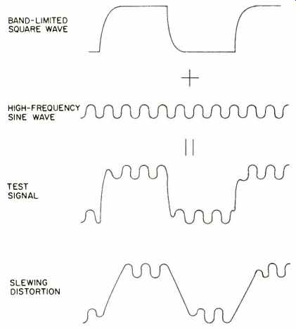
Fig. 10--A TIM test signal and what it looks like when an amplifier is slew-rate
limiting.
Although some feel that such a specialized signal is necessary to exercise amplifier TIM mechanisms [1, 3], others have more recently shown that ordinary high-frequency harmonic distortion measurements (THD) are just as good if not better [5]. This seems reasonable, because any nonlinearity which produces TIM also must produce harmonic distortion. A high-frequency sinusoid (like 20 kHz) also produces a significant rate-of-change for a large percentage of the time, so that an amplifier's TIM mechanisms are clearly exercised. Because the smaller peak time derivatives produced by a 20-kHz sinusoid are somewhat more in line with those produced by real music than those of the sine-square test, better subjective correlation may result. However, much more work needs to be done to determine which test, among these or others, yields the best overall subjective correlation.
That high-frequency THD is a reasonably dependable indicator of TIM performance is good news, since the FTC requires that all amplifier specifications must quote a maximum THD figure for the full rated frequency range (usually 20 Hz to 20 kHz) at rated power. TIM should be completely inaudible for units with 20-kHz THD figures below about 0.02 percent. However, the reader is cautioned that THD figures as high as 0.1 percent may still yield inaudible TIM under some circumstances. Until more work is done, these numbers can only be considered ballpark figures.
Conclusion
To summarize, TIM is simply a form of high-frequency intermodulation distortion which is induced by a signal's rate-of-change rather than amplitude alone. It can be excited by continuous signals, such as sine waves or square waves, or by noncontinuous signals like music. Because it is induced by a signal's time derivative, an amplifier's slew rate is the single most important design parameter, while the small-signal parameters of feedback factor and open-loop bandwidth are, by themselves, irrelevant to the avoidance of TIM. These small-signal parameters also have no direct influence on slew rate. Since there is no need for open-loop bandwidth to exceed program bandwidth, deliberate program bandlimiting is in most cases unnecessary. It goes without saying, however, that good open-loop linearity is very important, especially at high frequencies.
Another important observation is that recorded music is simply not as "fast" as some would have us believe. The inevitable pre-emphasis/de-emphasis process places significant limitations on the power bandwidth, and thus the relative rate-of-change, of the reproduced signals. As a consequence, most reasonably designed amplifiers may not be producing as much audible TIM as we might think, especially at reasonable listening levels. Audible TIM certainly does exist, but its omnipotence has probably been exaggerated somewhat. It is also important to realize that some amplifier designers were routinely providing good slew rates and low values of high-frequency distortion (hence low TIM) long before the term TIM became popular.
Although our discussion has concentrated on power amplifiers, it should be kept in mind that, with the exception of the power output stage, the mechanisms which generate DIM and TIM in power amplifiers also exist in low-level circuits, such as in preamplifiers. This is particularly true in circuits employing operational amplifiers. Many of these devices have a rather limited maximum gain crossover frequency (on the order of 1 MHz), and open-loop linearity is not always carefully controlled. In particular, slew rate is often inadequate, especially in unity-gain compensated circuits.
Externally compensated devices with carefully chosen compensation to match the selected closed-loop gain should be used for best results. Some of the FET op amps, providing unity-gain crossovers in excess of 3 MHz and slew rates above 5 V/ uS, are capable of superb performance.
By far the most important conclusion is that we can "have our cake and eat it too"; we can take full advantage of the distortion-reducing properties of negative feedback without increased risk of generating TIM.
by Robert R. Cordell (adapted from Audio magazine, Mar. 1980)
= = = =