Manufacturer's Specifications
Sensitivity: 9.3 dBf (1 .6 µV) for 35 dB of quieting; 14.7 dBf (3 µV) for 50 dB of quieting; 13.2 dBf (2.5 µV) for 3 percent total noise and harmonic distortion (IHF Usable Sensitivity).
Signal-to-Noise Ratio: 75 dB (mono).
Harmonic Distortion: 0.2 percent, 20 Hz to 15 kHz, mono or stereo; typically 0.08 percent at 1 kHz.
IM Distortion: 0.15 percent mono or stereo, any combination of frequencies, from 20 Hz to 15 kHz, with peak modulation equal to 100 percent or less; typically 0.1 percent.
Frequency Response:
Mono and stereo ±1 dB 20 Hz to 15 kHz, with 75, 50 or 25 microsecond de-emphasis.
Capture Ratio: 1 .5 dB.
Selectivity: Alternate channel 90 dB narrow, 110 dB super-narrow; adjacent channel 8 dB narrow, 60 dB super-narrow.
Spurious Rejection: 110 dB.
Image Rejection: 90 dB.
Maximum Signal input: 8 volts across 75-ohm antenna input.
Audio Hum: 75 dB down from 100 percent modulation.
Muting: 70 dB noise reduction between stations.
Muting Threshold: 2 µV to 1000 µV, variable.
SCA Rejection: 60 dB or more.
Stereo Separation: 50 dB at 1 kHz.
Stereo Filter: 10 dB noise reduction.
Audio Output: Variable, 2.5 V into 47 kilohm; fixed, 1 V into 47 kilohm.
General Specifications Power Requirements: 120 volts, 50/ 60 Hz, 25 watts.
Dimensions:
Front panel, 16 in. (40.64 cm) W x 5-7/16 in. (13.81 cm) H; chassis, 14 3/4 in. (37.47 cm) W x 4 13/16 in. (12.22 cm) H x 13 in. (33.02 cm) D.
Weight: 28 lbs. (12.73 kg).
Price: $1,995.00.
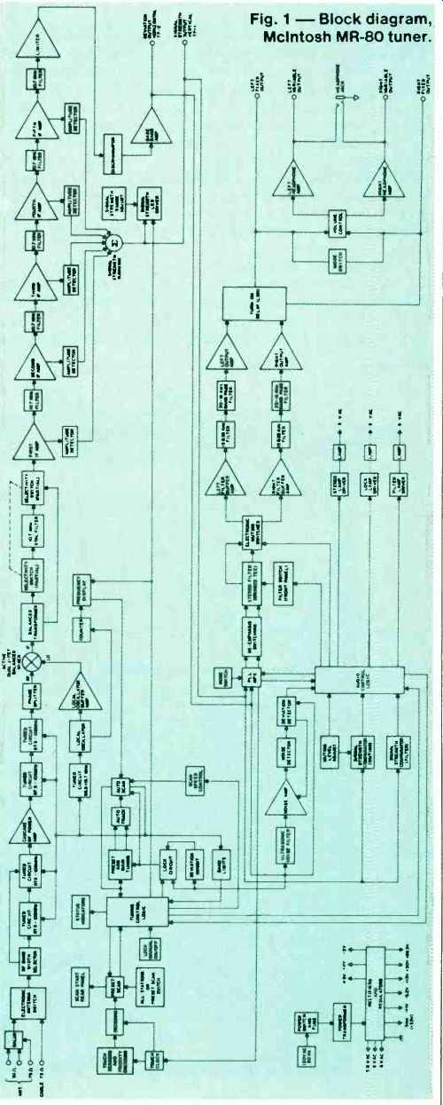
Fig. 1--Block diagram, McIntosh MR-80 tuner.
In all the years that I have been evaluating FM tuners, I have concluded that there are two basic approaches to the design of an FM tuner or the FM tuner section of a receiver. There are those engineers who design these products for other engineers, almost as if the users of their products will do nothing but measure them in shielded laboratory rooms. Then there are those engineers who design tuners to be used for listening to music broadcast by near and remote FM transmitters in the "real world." Seldom have I encountered a tuner that has been optimized both for the laboratory and for the nontechnical music lover.
The recently introduced McIntosh MR-80 FM tuner is such an optimized tuner. You will understand why if you follow my description and the results of my tests of this product.
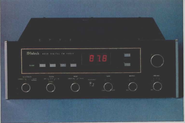
In terms of outward appearance there's no mistaking the MR-80 for anything but a McIntosh Laboratory product, with its familiar black front panel and its back-lighted nomenclature. But there is much that is new and up-to-date about this product's cosmetics, as well as its internal circuitry. Instead of a printed frequency dial scale, the upper section of the front panel is dominated by a large digital display which reads out the frequency of the tuned-to signal in Megahertz, to the nearest 100 kHz. This tuner does not employ frequency synthesis nor does the manufacturer claim that it does. One could argue about the use of the word "digital" in connection with this tuner, since that has come to mean a frequency-synthesized tuning system to a great many audiophiles, but that is largely a semantic argument these days, since many manufacturers of tuners who employ digital readout of frequency have begun to refer to such products as "digital" FM tuners.
To the left of the digital frequency display are four "touch pad" switches which are used to select one of four preset station frequencies. When one of these pads is touched, a small rectangle of light appears above the pad to indicate that the tuning command has been executed. To the left of these preset selector pads are three indicator lights. The red stereo light comes on when a stereo transmission is received. The second, an amber-colored indicator light, is identified by the word "lock" and indicates when the tuner is locked to an incoming station signal. The third, a green-colored light, indicates when the stereo multiplex filter is active.
To the right of the digital frequency display is a column of tiny LEDs arranged vertically; they indicate signal strength. No center-of-channel indicator is necessary since, as we shall see, the unique locking circuitry of this tuner insures proper tuning. Two more touch pads to the right of the signal-strength column are labeled "Auto Scan" and are used to make the tuner tune up and down the FM dial, stopping at received station signals. Finally, to the right of the auto-scan pads, we find a conventional tuning knob for manual tuning. There is a fourth method of tuning the M-80 which we will discuss when we examine the rear panel.
The lower section of the front panel of the MR-80 is equipped with six rotary controls and a centrally located stereo headphone jack which is driven by its own audio amplifier circuitry and can deliver 2.5 volts of signal into 600-ohm loads; more than enough to drive low impedance phones, incidentally. Starting at the left, there is a two-position selectivity switch, with settings identified as "Narrow" and "Super Narrow." Normally, the "Narrow" position is used, and in our tests we found that it provided excellent alternate-channel selectivity and the ability to separate closely spaced signals in our listening area. We have been told by some of our friends and colleagues, however, that there are some areas of the country in which high adjacent-channel selectivity is a must if listeners are to be able to tune to distant, weak signals without being swamped by strong local-station signals separated in frequency from the remote desired signal by only one channel bandwidth, or 200 kHz.
The next rotary switch activates the stereo multiplex filter circuitry, either permanently when set to "in" or, when set to "auto," automatically whenever stereo signal strength falls be low 100 microvolts or so. Since activation of the filter is always accompanied by an indicator light mentioned earlier, the listener is always aware of the filter being turned on, even if turn-on occurs automatically.
A stereo/mono mode switch follows, and to its right, beyond the headphone jack, is a continuously variable control called "scan" which determines the speed of tuning when in the scan tuning mode. A variable-muting control comes next, which is used to set muting threshold and also determines scanning sensitivity, that is to say how strong an incoming signal must be in order for the auto-scan tuning system to stop on that signal.
Finally, the right-most control, located just below the tuning knob, is a master output level control which determines audio level at the variable output jacks on the rear panel and which, when rotated fully counterclockwise, disconnects power to the tuner.
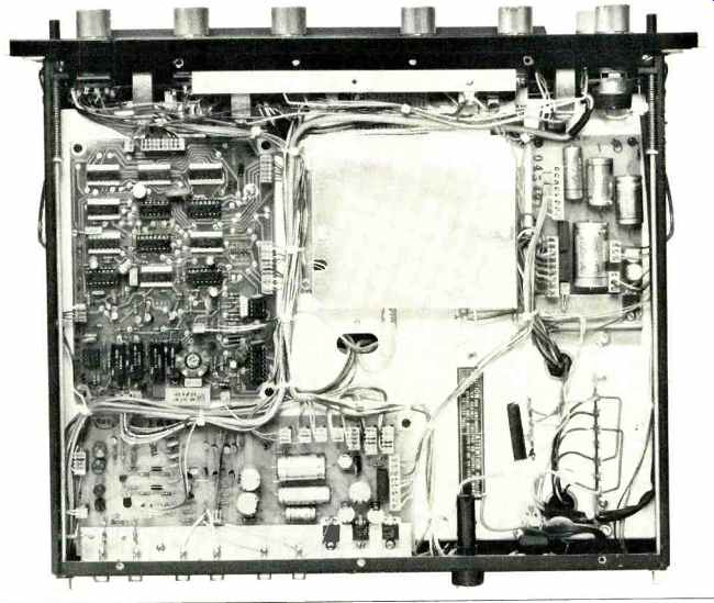
-------top inside view
The rear panel of the MR-80 is equipped with two 75-ohm coaxial antenna connectors (one of which is intended for commercial cable input), 300-ohm antenna terminals, and a ground terminal. A jack nearby accepts a plug on the end of a supplied long cable that allows the user to either scan or call up the preset stations, one by one, from a remote location, depending upon the setting of a nearby slide switch. Variable and fixed level output jack pairs are at the lower right of the rear panel, while nearby are a pair of scope jacks (horizontal and vertical) intended for connection to an oscilloscope for observation of multipath (reflection) problems. A line fuse-holder and an unswitched convenience a.c. power receptacle complete the rear panel layout.
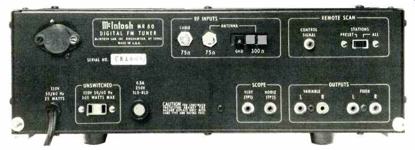
----------rear view
Additional adjustments and controls are located along the top surface of the tuner. These include four continuously variable rotary controls which are used to set up the frequencies of the four desired preset stations, a rotary control which adjusts the sensitivity of the signal-strength LED column display (you can set it so that the strongest station in your area will cause full-scale readings), and five small push-button switches. An r.f. preselect circuit is activated by the first of these buttons and adds a tuned circuit between the antenna and the first r.f. stage to immunize against strong signal overload. The next button selects the cable or your own antenna input. The third button can be used to disable the locking circuit. The last two buttons provide selection of either 25, 50 or 75 microsecond de-emphasis characteristics.
Circuit Highlights A block diagram of the circuitry of the McIntosh MR-80 is reproduced in Fig. 1. An electronic antenna switch selects signal inputs either from the cable input or from one of the direct antenna inputs and feeds the signal to the first r.f. amplifier which consists of a low-noise junction FET and a high-power bipolar transistor arranged in cascode configuration. Two PIN diodes are used to insert a second preselector stage during strong-signal reception. Tuned circuits are tuned by a series-parallel connection of four matched varactor diodes which are tuned by relatively high voltage (5 to 26 volts) to eliminate diode nonlinearities and possible IM distortion. Two parallel tuned circuits follow the r.f. amplifier to improve image rejection and increase r.f. selectivity.
The balanced mixer stage is a matched-dual-FET and bipolar transistor circuit. A low-loss, toroidal, phase-splitting transformer is used as an impedance matching network in the gate circuit of the mixer. A bipolar transistor is used as an oscillator buffer to prevent oscillator pulling on strong signals and as the constant-current source for the dual J-FET mixer.
Four differential amplifiers, coupled with linear-phase monolithic filters, comprise the narrow selectivity and signal-strength sections of the i.f. amplifier. A four-pole, four-zero crystal filter is inserted in the signal path as well when the "Super Narrow" selectivity setting is selected. A solid-state signal-strength meter is used as a front panel indicator of incoming r.f. signal strength.
This meter can be user-set to give a full scale indication on a signal as low as 2 microvolts or as high as 100,000 microvolts.
Signal-strength voltage is also used to control mono-stereo switching, automatic stereo filter insertion, muting, and automatic scan stop. The control voltage also adjusts stereo separation at low r.f. signals so that, unlike many other tuners, there is no abrupt change from mono to stereo in the presence of marginally weak signals; reduced separation also produces the best possible signal-to-noise ratio at weaker signal strength levels.
The limiter following the selectivity section of the i.f. amplifier has a total gain of 80 dB for extremely hard limiting with good impulse-noise rejection. A broadband Foster-Seeley discriminator is used as the FM demodulator, and output of the detector is fed to a buffer stage for isolation from variations in load impedance.
The phase-locked loop stereo-decoder IC incorporates two special new systems, the automatic variable-separation control circuit mentioned earlier and tri-level digital waveform generation which helps to eliminate interference from SCA signals and from the sidebands of adjacent-channel FM signals. Following the de-emphasis switches, an electronically switched filter circuit is used to reduce out-of-phase noise when receiving weak signal stereo. The filter is actually a twin-T bandpass that blends high and low frequencies, but leaves separation unaffected at mid-frequencies for improved stereo imaging when the filter is required. LC notch filters further reject any residual 19-kHz or 38-kHz sub-carrier output products. A separate headphone amplifier, capable of driving low impedance phones, also serves as the main output amplifier.
Tuning, Scanning and Control Circuitry
A detailed explanation of the touch sensor, preset scanning, control logic, scan circuit and lock circuit, as well as of the frequency counter and power supply circuitry is provided in the excellently written owner's manual supplied with the MR-80, and full schematic diagrams are also included for the benefit of the technically oriented user or for possible servicing needs. The descriptions of the remaining non-r.f./i.f. related circuits are too lengthy for even an abbreviated treatment here, but we cannot leave this subject without providing a brief explanation of the unusual "lock" circuitry designed into this unusual tuner. This new circuit will be correctly tuned even if the station (or, more likely, the cable company) is not on its correct frequency. Two operational amplifiers are used. A deviation signal from the detector is fed to the first amplifier, which produces an output voltage proportional to the logarithm of the d.c. component in the detector output. A second amplifier, connected as a switched-gain low-pass filter, removes any audio signals present. The filter output, which is a correction voltage, is fed into a scaling circuit that compensates for the tuning diodes' nonlinear frequency-to-voltage response. Both amplifiers operate with more than 50 dB of gain at d.c. So, with a closed-loop gain of more than 100 dB, tuning error (when locked) is less than 1 kHz at 100 MHz. This error is less than that obtained with most frequency-synthesized circuits and provides the additional benefit of correct tuning even if the station or cable signal is not on proper frequency.
Since this circuit will "track" a station even if it drifts by more than 1 MHz in either direction, the user must be able to defeat the lock easily. The touch sensor switching arrangement on the manual tuning knob takes care of this and, to prevent the tuner from locking onto a strong signal next to a weak signal, a circuit is used to sense strong adjacent channel signals and to inhibit the lock circuit in such circumstances. The lock on/off switch on the top surface of the unit, incidentally, will cancel the lock only insofar as the manual tuning knob is concerned. The lock circuit continues to work for all the preset signals and for the scan circuits.
Laboratory Measurements
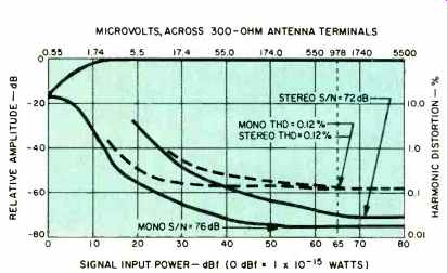
Fig. 2--Mono and stereo quieting and distortion characteristics.
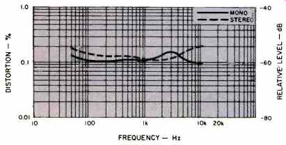
Fig. 3--Harmonic distortion vs. frequency at 100 percent modulation.
The multi-purpose graph of Fig. 2 shows the mono and stereo quieting and distortion (at 1 kHz) characteristics of the MR-80 tuner with the selector switch set for "Narrow" (normal) selectivity. Usable sensitivity in mono measured 12.0 dBf (2.2 µV), while for stereo, the usable sensitivity was a very low 20 dBf (5.5 µV).
The 50-dB quieting point was reached with input signals of 3.5 µ V (16 dBf) in mono and 30 dBf (17.4 µV) in stereo, the stereo result being about the lowest we have ever measured for any stereo FM tuner. At 65 dBf of input signal strength, signal-to noise ratio measured 76 dB in mono (as opposed to 75 dB claimed by McIntosh) and 71 dB in stereo. Distortion at that strong signal level was the same in mono and stereo, a low 0.12 percent for a 1-kHz signal.
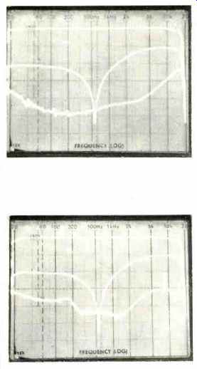
Fig. 4--Frequency response and separation with selectivity circuitry in "Narrow" mode.
Fig. 5--Frequency response and separation with selectivity circuitry in "Super Narrow" mode.
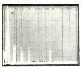
Fig 6--Crosstalk components for a 5-kHz input signal.
Figure 3 is a plot of distortion (harmonic) versus modulating frequencies, for both mono and stereo operation of the tuner, again with selectivity set to the normal or "Narrow" position. We measured specific values of 0.12 percent at 100 Hz for mono, and 0.15 percent for that frequency in stereo. At 3 kHz, mono distortion was a bit higher than that measured in stereo, 0.18 percent as against 0.13 percent, but at the highest required test frequency of 6 kHz, stereo THD came close to the 0.2 percent limit while mono distortion was again a low 0.1 percent.
We should point out that when the "Super Narrow" selectivity setting is used, distortion does rise rather significantly, approaching the 1.0 percent mark, but this is a trade-off that was most deliberately chosen by McIntosh Laboratory's designers.
There is just no other way to achieve adjacent-channel selectivity of 60 dB without increasing distortion in the stereo mode where sidebands of high frequency modulating signals extend well be yond the single channel width of 100 kHz to either side of center carrier frequency. What is remarkable, in fact, is that McIntosh was able to achieve this sort of adjacent-channel selectivity and still keep the distortion level in stereo under 1.0 percent! It should be noted, incidentally, that noise performance or signal to-noise ratios remain essentially the same in the "Super Nar row" setting as they were in the "Narrow" or normal selectivity mode.
The spectrum analyzer plots of Fig. 4 illustrate frequency response and separation characteristics of the tuner measured with selectivity set to the "Narrow" or normal position. We measured a separation of 50.5 dB at 1 kHz, 48 dB at 100 Hz, and 35 dB at 10 kHz. The lower trace in the scope photo shows the crosstalk in the unmodulated channel. The center trace shows what happens when the multiplex filter circuit is introduced.
While separation at the frequency extremes diminishes, notice that at mid-frequencies it is actually greater than it was without the filter over a narrow region of frequencies around the 500-Hz mark.
As might be expected, when selectivity is switched to the "Super Narrow" mode, separation suffers somewhat, as illustrated in the scope photo of Fig. 5. In addition, we note the appearance of some beats at around 9 kHz and at 19 kHz in the unmodulated channel output. Again, these are some of the trade-offs that must be made to obtain the kind of adjacent channel selectivity of which the MR-80 is capable. And that kind of selectivity can only be appreciated by the listener who, having been unable to receive a preferred station because of strong local station interference, suddenly hears the desired signal with absolutely no interference.
In Fig. 6 we have changed the sweep mode of our spectrum analyzer so that it is linear (in previous scope photos it was logarithmic as indicated by the frequency notations at the top of the display), and printed frequency notations should now be ignored. The sweep is from 0 Hz to 50 kHz, at 5 kHz per division. The tall spike at the left is the 5-kHz output from the modulated channel. Contained within that spike is the opposite (un-modulated) output from the other channel, while to the right of these are the crosstalk products at harmonics of 5 kHz as well as any residual 19-kHz and 38-kHz subcarrier output products, all of which are about 60 dB or more below the level of 100-percent modulation.
Capture ratio measured exactly 1.5 dB as claimed, while image rejection was in excess of the 90 dB claimed as a limit specification. We were unable to measure alternate channel selectivity in the "Super Narrow" mode (our equipment can only read reliably to 100 dB) but were able to confirm all other selectivity readings claimed by McIntosh in both the "Narrow" and "Super Narrow" modes of the i.f. system.
Use and Listening Tests
Since our own local distribution of FM stations was such that we did not run into adjacent channel problems if we used a good directional antenna in our listening tests, these tests were divided into two separate parts. First, we did some off-air testing and found that the MR-80 picked up more usable signals than any tuner we have tested over the last three years. The automatic blend filter action and the variable separation (which occurs automatically) resulted in stereo reception of weak signals that was completely acceptable from a noise point of view but that would have been too noisy for pleasurable listening with other tuners we have tested in recent months. The "lock" circuit always yielded optimum tuning point, as evidenced by a complete absence of audible distortion. In short, as we said at the outset, the MR-80 is designed to cope with the real world of broadcasting.
As proof that it could respond well to the world of the laboratory (and because we wanted to see just how sharp that "Super Narrow" selectivity position was) we conducted additional tests which amounted to a "closed circuit" experiment. Using our Sound Technology Model 1100A "Signal Conditioner" (which accepts program modulation from tape or discs and applies required pre-emphasis) to modulate our primary FM stereo signal generator, we "transmitted" some of our favorite discs and master tapes both by direct cable connection and by low-power radiation from one room to the next. These experiments were conducted at a variety of signal strength levels, ranging from around 50 microvolts to 100,000 microvolts. The dynamic range capability of the tuner was awesome, better than any of the program material we used in these experiments.
All of which brings us to the same conclusion we have reached when testing other excellent tuners in the past. Before investing in a tuner of this excellent quality and performance capability, ascertain whether or not there is any station in your area that is meticulous enough in its broadcast practices and caring enough in its selection of program sources to justify the relatively high price of the Mac MR-80. If you are fortunate enough to have one or more such stations in your area and are also sufficiently affluent (or possessed of a good enough credit rating) to afford the MR-80, I could not recommend any product more highly. The McIntosh MR-80 is what FM and stereo FM is really all about -- or should be.
--Leonard Feldman
(Source: Audio magazine, Mar. 1981)
Also see:
McIntosh MC2600 Amplifier (Equip. Profile, Feb. 1992)
Link | --McIntosh MC 7200 Power Amplifier (Jan. 1990)
McIntosh Model C-27 Stereo Preamplifier (Sept. 1978)
Mcintosh MC 2002 Amplifier (Equip. Profile, Apr. 1985)
= = = =