by Ronald Wagner
Ronald Wagner is the author of Electrostatic Loudspeaker Design and Construction. Since 1968, he has been experimenting with electrostatic loudspeaker design.
The primary purpose of a loudspeaker is to convert electrical energy into acoustical energy. This transfer, in a conventional or electromagnetic speaker, is a function of the force produced by a magnetic field. Basically, this type of speaker is made by connecting a coil of wire, wound on a form, to a paper or plastic cone. The coil is positioned inside a magnetic field produced by a permanent magnet. As the current from an audio amplifier flows through the coil, it creates another magnetic field. The relative polarity of the two fields will either produce a force of attraction or repulsion. The cone, which is attached to the coil, will follow this movement and will excite the air molecules next to its surface. This molecular movement will travel in waves away from the source. When it is detected by the ear, the brain will interpret this motion as a sound coming from the loudspeaker.
While the above type of sound reproducer is the most common, it is not the only type of transducer that can shift energy from the electric to the acoustic realm. Many aficionados of sound reproduction have discovered the outstanding performance of electrostatic loudspeakers (ESLs).
The name alone implies that there is a difference between electrostatic and electromagnetic speakers. While a conventional speaker relies on the force produced by a magnetic field, an ESL uses an electric field to accomplish a similar task. Because the electrostatic forces are usually smaller than their electromagnetic counterparts, the material that moves the air molecules must be much lighter.
HISTORICAL BACKGROUND
The principles which govern the performance of an ESL have been known for many years. The development of ESLs, however, was hindered by numerous problems. In the early days (before World War II), the limitations were mainly in the materials needed to make the diaphragm. Although this problem reduced the commercialization of ESLs, I did not stop their development. One inventor's solution was to make the diaphragm out of a cloth that had been impregnated with a metallic thread.

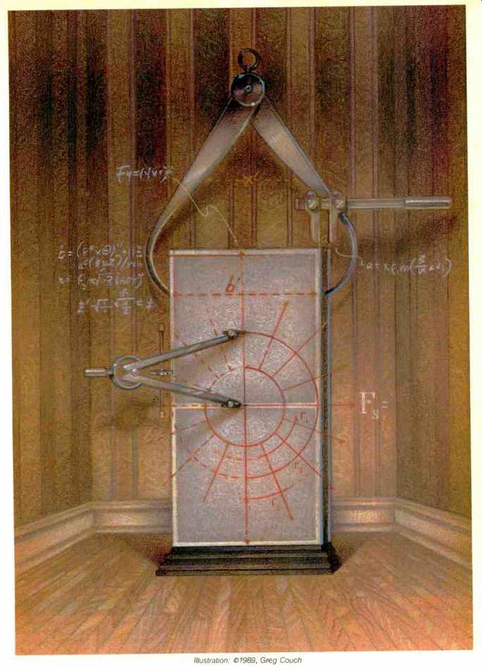
--- Electrostatic loudspeaker designed by the author.
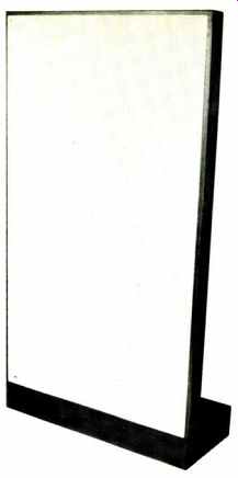
Fig. 1--An electrostatic speaker from Sound-Lab that has multiple diaphragms.
The most significant contribution to the development of the ESL was Mylar, invented by scientists at DuPont and patented in 1949. Since then, most commercial electrostatic speakers have used this material for their diaphragms. One of the first was made by Arthur Janszen. In the early '50s, Janszen produced an electrostatic tweeter array. His product was usually paired with a bookshelf speaker from Acoustic Research. Later, Janszen produced a full-range speaker, and it became known as the KLH Model Nine.
Another well-known speaker of that era was the Pickering Isophase. It was produced by the Pickering Company, which also made some of the best and most widely accepted phonograph cartridges. Unfortunately, this electrostatic speaker never enjoyed the same popularity.
In the United Kingdom, Peter Walker of the Acoustical Manufacturing Co. and D. T. N. Williamson of Ferranti Wireless Works designed and produced the first Quad electrostatic speaker. This ESL enjoyed many years of successful production, but in 1982, it was replaced by a newer and improved model, the Quad ESL-63.
Although each of the early electrostatic speakers had unique characteristics, they had trouble competing with conventional speakers. Besides having high price tags, ESLs lacked the power needed to adequately reproduce bass frequencies. Another factor affecting their acceptance was the public's opinion about what represented good bass response. Most listeners of that time associated good bass with the boomy box speakers that were popular in the '50s and early '60s.
Gradually, as the public's appreciation of high-quality sound improved, so did the technology of the electrostatic speaker. The Quad Model ESL-63, for instance, has an increased diaphragm area and uses an electrical delay line to create a sound field with a spherical wavefront. Not only is this a significant accomplishment for a flat diaphragm, but the result closely resembles the way a sound is produced by an ideal source.
In the early '70s, the engineers at Koss came up with another interesting concept for improving the performance of ESLs. Their idea was to increase the number of diaphragms.
Many years later, in 1985, Harold Beveridge patented a technique for making a multiple-diaphragm speaker. Today, the Sound-Lab Co. of Park City, Utah makes an electrostatic speaker (Fig. 1) that uses a multiple diaphragm. It is this configuration which produces the serial function.
ELECTROSTATIC PRINCIPLES
Electrostatics is the science of electricity which deals with objects that have been electrically charged. When an object is charged, it will be surrounded by an electric field. This field, in turn, will produce a corresponding electrostatic force. If an uncharged object is brought near one that has been charged, it will be influenced by the force which surrounds the charged object. When two charged objects are situated near each other, they will produce an interactive force. The direction of this force is determined by the polarity of the charges and is similar to the force that exists around two magnets.
That is, like charges will repel each other, and unlike charges will have a force of attraction.
ELECTRIC CHARGE
People are usually aware that liquids, gases, and solids are made up of many atoms. Every atom, in turn, has two basic parts. In the center is the core, or nucleus, which has a positive charge. Orbiting this core is one or more electrons, each of which has a negative charge. The material's characteristics will determine how many electrons revolve around the nucleus.
In most materials, the positive charge on the nucleus is equal to the negative charge produced by the electrons, thus, the atom remains neutral.
One important characteristic of an atom is its ability to gain or lose electrons. When it gains an electron, an atom is called a negative ion. This means that it will have a negative charge. Similarly, if an atom loses an electron, it becomes a positive ion and will have a positive charge.
The charge acquired by an object is determined by the total number of electrons revolving around the nucleus of each atom. Normally, this charge is very small, which makes it inconvenient to use in calculations. To overcome this situation, electrical charge is measured in coulombs; 1 coulomb is equal to 6.28 x 10^18 electrons.
ELECTRIC FIELD
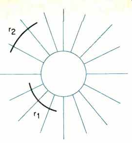
Fig. 2--Electric field around a charged object. Note how field density (strength
per unit area) decreases from position r1 to position r2.
If a spherical object is electrically charged, there will be a uniform electric field surrounding it. This is shown in Fig. 2. The lines spreading out from the sphere represent the lines of the electric field, which diverge as they get farther away from the sphere. The strength of the field, at any distance, is dependent on the number of lines per unit area. At the inner arc (r1), the electric field is greater than at the outer arc (r2). For any position around the charged sphere, the strength of the electric field can be calculated by:
Fs = k x Q / R^2 (1)
where FS is the field strength, in newtons per coulomb; k is a constant that depends on the units of measurement (in this case, 9.07); Q is the electric charge, in coulombs, and R is the radial distance from the sphere, in meters.
FORCE OF AN ELECTRIC FIELD
If an object is located some distance from a charged sphere, it will be influenced by the force of the electric field.
This force can be calculated by:
F=F_s x Q (2)
where F is the force, in newtons. The above formula only applies to a single object that has been placed in an electric field. It also assumes that the object is small and does not disturb the electric field produced by the sphere.
When two charged objects are near each other, the force between them is equal to:
F= k x Q1 x Q2/R^2 (3)
where Q1 is the charge on one object; Q2 is the charge on the other object, and R is the distance between objects, in meters. As an example of this last equation, suppose two spheres are located 1 meter apart. Each of the spheres has a negative charge of 1 coulomb. The force between the spheres (equation 3) is equal to:
F=9.07 x -1 x -1
= 9.07 newtons.
Multiplying this result by 0.248 will produce an answer in pounds of force.
Because both spheres have the same polarity, the force between them is one of repulsion. Changing the charge polarity, on either one of the spheres, will produce a force of attraction.
SPEAKER CAPACITANCE
In electronics, a device that has two or more plates and stores energy in an electric field is called a capacitor. An electrostatic speaker is analogous, in this respect, because it will store energy in the electric field between the plates and the diaphragm.
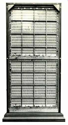
Fig. 3--An electrostatic speaker without its grille cloth. Note the grid
perforations in the plate. (From Electrostatic Loudspeaker
Design and Construction,
by the author.)
In an ESL, the energy-storage capacity is determined by the size of the plates and by the distance between them and the diaphragm. This capacity is measured in an electrical unit called the farad. The difficulty associated with the farad is that it is too coarse or large. Therefore, the storage capacity for a capacitor or an electro static speaker is indicated in smaller units, such as the microfarad (µF) or the picofarad (pF). The microfarad is one-millionth of a farad, while the picofarad is one-millionth of a microfarad.
The storage capacity of an ESL is also dependent on the material that separates the plate from the diaphragm. Usually, this space is filled with air, and the capacity can be determined by:
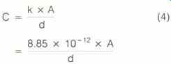
...
where C is the storage capacity, in farads; k is a constant that assumes the separation is filled with air and is equal to 8.85 x 10^-12; A is the area of the plates, in square meters, and d is the distance between either plate and the diaphragm, in meters. For a speaker with a plate size of 24 inches x 24 inches, the equivalent area is 0.372 square meter. If the distance between either one of the plates and the diaphragm is 0.0625 inch, this corresponds to 1.5875 x 10^-3 meter. Using these metric values in equation 4, the storage capacity for this speaker becomes:
C=(8.85 x 10^-12)0.372 / 1.5875 x 10^-3
= 2,074 pF.
This is the capacity between the diaphragm and either one of the plates.
At this point, most of the basic factors pertinent to the field of electrostatics have been defined. This information can now be used to describe how they are incorporated into an electrostatic speaker. Before doing this, however, the following section will briefly describe how an ESL is made.
ESL CONSTRUCTION
The photograph shown in Fig. 3 is an ESL with its grille cloth removed. This particular speaker system consists of two speaker panels plus some associated electronics. Because the two panels are the same, the following description can be applied to either one.
The easiest way to visualize how an electrostatic speaker is made is to think of it as a cheese sandwich. The "bread" is a pair of plates. In addition to being conductive, the plates must also be acoustically transparent. This is accomplished by making them out of a perforated material whose open area is approximately 50% of the total plate area.
The "cheese" is a thin, movable, conductive diaphragm. Just as a real sandwich's cheese and bread are often separated by butter, the speaker's diaphragm and plates are isolated by a layer of air. The diaphragm is supported by stretching it over a set of spacers located at the outer edge of the speaker panel. The diagram in Fig. 4 illustrates the basic construction of an electrostatic speaker.
ESL ELECTRICAL CHARACTERISTICS
The electrical characteristics of an ESL can be divided into two parts. The first will cover those factors that are associated with a stationary diaphragm, and the second will address what happens when the diaphragm is moving.
The charge used in an electrostatic speaker is produced by a high-voltage power supply. Its purpose is to establish a linear electric field between each of the plates and the diaphragm. Its output voltage is determined by the type of speaker. A bass speaker, for instance, has a large plate-to-diaphragm separation. To establish the same linear electric field, it will require a greater voltage than either a midrange driver or a tweeter requires. As shown in Fig. 5, this power supply is connected between the two plates and the diaphragm.
DIAPHRAGM FORCE
When the high voltage is applied, each plate produces a force of attraction for the charge on the diaphragm.
This force is equal to:
F=9.07xQ / d2 (5)
This equation is similar to equation 1 in the section on the electric field. In this case, Q is the charge between either of the plates and the diaphragm. Its value can be determined by:
Q=CxV (6)
where C is the plate-to-diaphragm capacity in farads, and V is the voltage between the plates and the diaphragm. For a loudspeaker having a capacity of 2,074 pF and a power supply, or bias voltage, of 3,000 V, the charge is:
Q = 2.074 x 10^-9 x 3,000
= 6.22 x 10^-6 coulomb.
Inserting this value into the force equation (equation 5) provides the following result:
9.07(6.22 x 10^-6)
F (1.5875 x 10^-3)2
= 22.4 newtons or 5.55 pounds.
Because the diaphragm and the conductive plates have opposite polarities, the force is one of attraction and tends to draw the diaphragm toward the plates. Because of the speaker's symmetrical construction, the diaphragm stays in stasis, equally attracted toward each plate.
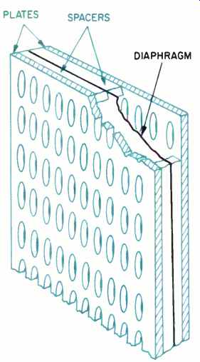
Fig. 4--In an electrostatic speaker, a moving diaphragm is fastened by spacers
halfway between two charged plates.
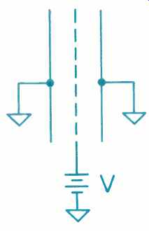
Fig. 5--The d.c. polarizing (bias) voltage is applied between the two plates
and the diaphragm. See text.
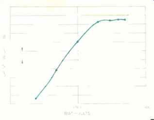
Fig. 6--How bias voltage affects speaker output for a 100-Hz test signal.
FIELD STRENGTH
The application of a voltage between the plates and the diaphragm brings to bear another important speaker characteristic. In this case, it is the strength of the electric field. This value is usually specified in volts per mil (V/mil) and can be calculated by:
E=V/d (7)
where E is the field strength, in V/mil, and d is the distance between either plate and the diaphragm, in mils (1 mil equals 0.001 inch). For a speaker with a plate-to-diaphragm spacing of 0.0625 inch and a polarizing voltage of 3,000 V, the field strength is 3,000 divided by 62.5, or 48 V/mil. The significance of this parameter is implied by Fig. 6, which shows how changing the polarizing voltage affects speaker output level.
FIELD, STRENGTH LIMITS
The maximum limit to the field strength is determined by the material used to separate the charged surfaces. During an electrical storm, you see what happens when this material limit is exceeded. The two charged bodies have produced a very large electric field. When the strength of this field exceeds the limit of the material that separates them-in this case, the air-there is a flash of lightning.
For an ESL, the maximum limit is determined by the strength of the air gap. If enough voltage is applied across the plate-to-diaphragm spacing, the air between the plate and diaphragm will also break down. When that happens, a spark will jump between the two charged surfaces. The maximum voltage that can be placed across the air gap of an electrostatic speaker is 75 V/mil.
MAKING THE DIAPHRAGM MOVE
The preceding material has described some of the factors that affect an ESL with a stationary diaphragm. To make the diaphragm move, the plates must be connected to a source of a.c. voltage. The method for applying this voltage is shown in Fig. 7A. When the a.c. voltage from the source (es) is zero, the diaphragm will be in its centered position. As the source voltage increases, it will produce an a.c. voltage between points a and c in Fig. 7A.
The polarity of the voltage on the plates is determined by both the transformer connections and the a.c. signal.
If the voltage between a and b has positive polarity, then the voltage between b and c will be equal in amplitude but have negative polarity. When the alternating voltage has reached its positive peak, the diaphragm will have reached the maximum limit of its excursion. In Fig. 7A, it will be closer to the plate connected to terminal c of the transformer. When the voltage reverses itself and the input reaches its negative peak, the diaphragm will be closer to the opposite plate.
In his 1954 book, Electroacoustics, F. V. Hunt of Harvard defined the relationship between the alternating voltage and the force on the diaphragm.
Hunt stated that if an ESL uses a constant potential difference to establish a force on a moving diaphragm, it will have a nonlinear output; i.e., its output will be distorted. The solution he proposed was to create a constant charge on the diaphragm, achieved by placing a very large resistance in the power supply's output (Fig. 7B). The resistor does not affect the static force produced by the bias voltage.
To maintain a constant charge, the moving diaphragm must not produce a current flow in the resistor. This is accomplished by making the time constant, T = RC, very long. The R in this equation is the value of the resistor, and C is the speaker's capacitance. If the time constant is greater than the half period of the speaker's lowest frequency, there will be no current flow through the resistor, and the diaphragm will have a constant charge.
Once the diaphragm is charged, the a.c. voltage between a and c will produce an alternating force. When this voltage reaches its peak value, the force of attraction on the charged diaphragm is equal to:
F=ExQ (8)
where E is the field strength, in volts per meter (V/meter), and Q is the charge on the diaphragm.
To obtain the maximum acoustic output, the peak-to-peak value of the a.c.
voltage must be equal to the field intensity set by the charging voltage. Because the plate-to-plate separation is twice the plate-to-diaphragm spacing, the a.c. voltage must be at least twice the charging voltage. For a field intensity of 48 V/mil and a spacing (plate to plate) of 125 mils (0.125 inch), the a.c. voltage must be 6,000 V. Converting mils to meters, our field intensity of 48 V/mil comes to 1.9 x 10⁶ V/meter.
We have previously calculated a diaphragm charge of:
2,074 pF x 3,000 V
= 6.22 x 10^-6 coulomb.
Using equation 8, we multiply this charge by the field intensity to derive the force:
F = (1.9 x 10^6)(6.22 x 10^-6)
= 11.82 newtons.
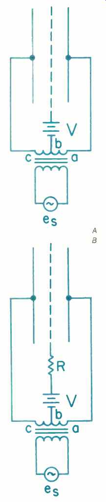
Fig. 7--Two ways of connecting d.c. bias and a.c. signals to an ESL. While
simply coupling the signal to the plates (A) will work, the addition of a
large resistance in the output power supply (B) keeps the diaphragm charge
constant, for more linear operation.
DIAPHRAGM POWER
The power required to move the diaphragm can be determined by using the rms values for both the force and the distance. That is:
P=Frms x drms / t (9)
where P is the power required to move the diaphragm, in watts, and t is the time required to move the diaphragm.
For a frequency of 100 Hz, this power is equal to:
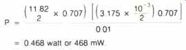
At this point, we've covered the history of electrostatic speakers, basic electrostatic principles, and an analysis of the forces that make the diaphragm move.
In Part II, we'll cover the transformer that acts as a signal interface between an amplifier and an ESL's diaphragm, acoustical parameters, and ways to improve an ESL's performance.
Suggested Reading
Hunt, F. V., Electroacoustics, Harvard University Press, Cambridge, Mass., 1954. (This book has recently been republished by the Acoustical Society of America.) Wagner, Ronald, Electrostatic Loudspeaker Design and Construction, Tab Books, Blue Ridge Summit, Pa., 1987.
(adapted from Audio magazine, Mar. 1989)
Continued here:
Electrostatic Speakers: Theory and Practice -- Part 2 (Apr. 1989)
Also see:
Build An ES Tweeter / Cone Woofer System (Aug. 1974)
Speakers by Design by Ken Kantor -- Part 1 (Nov. 1988)
= = = =