Peak Level Indicator
Q. I like to listen to music at very loud levels.
My question is: can I hook up some type of flashing light or buzzer circuitry to warn me of the high power levels which can damage my speakers?
-Douglas Parker, Los Angeles, Cal.
A. I do not suggest a buzzer for this application as its sound may be drowned out by the "very loud level" at which you plan to listen.
The information you need can be obtained by the use of a neon lamp connected to the secondary of a step up transformer. You could use an ordinary output transformer for this application, connected backwards. You would need to protect the neon lamp with a suitable series resistor. You also must provide some means of calibrating the system. See Fig. 1.
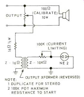
Fig. 1--Peak level indicator.
Neon lamps fire on peaks, responding quickly to excitation. However, these peaks must he of relatively high voltage, more than 90 volts. This is more than is available from an amplifier feeding 8-ohm speakers, even when this amplifier is putting out really high power. Under these conditions, the current is high, but the voltage is low. That is why the step-up transformer is needed. The ordinary output transformer will produce too high a voltage. Further, the neon lamp will tend to draw too much current even when the voltage is just above the ignition point. It is for this reason that a series resistor must be used to feed the lamp.
The calibrating pot is used to set the point at which the lamp fires. I suggest that you calibrate the lamp to flash at a point somewhat below the actual danger point. Check the calibration from time to time to be sure that the neon lamp has not changed its firing characteristics.
Unusual Hum Problem
Q. I have a tube-type amplifier. Since purchasing it, I have lived in three different apartments. Here is where the problem begins.
In the first apartment the amplifier produced an audible hum. I checked out all the tubes, circuits, cables, and shielding. All seemed well. I noticed that, when the noise was most audible, one of the tubes glowed red hot and another gave off a violet color. Also, the hum would continue at a constant level, then suddenly increase in volume, and then return to the constant level. The sound was there with either "phono" or "tuner". I moved into my second apartment. I wired everything up. I had no hum, no glowing tubes--just very acceptable performance from my system.
In my third apartment I am again plagued with the hum and glowing tubes. What causes the hum? What can be done about it? Would I have the same problem with a transistor amplifier?
- Richard Peterson, Iowa City, Iowa.
A. I suspect that the differences in your amplifier's performance in your three apartments results from variations in line voltage. When you lived in the apartment which produced the humless amplifier operation, I suspect that the line voltage was lower than normal. Higher line voltages brought about the condition.
I do not know anything about your particular amplifier, inasmuch as no brand was indicated. All I can do, therefore, is give you some general observations with the hope that one of them will be the right one.
Many amplifiers employ what is known as "fixed bias." This is an arrangement whereby bias for the output tubes is obtained from a bias supply rather than from a cathode biasing resistor. Perhaps this "fixed bias" voltage is too low.
Usually this can be corrected by a pot incorporated in the amplifier for this purpose. Sometimes this adjustment takes the form of two pots, one for each output tube (in the case of a mono amplifier ). Assuming that this bias voltage is too low, the output tubes will draw too much current, which, in turn, will lead to a gassy condition in the tubes and hum in the amplifier. As you can guess, when the line voltage is reduced, the output stage will not draw as much current, and the gassy condition will not take place.
How much bias should be applied to your output tubes? Check a tube manual. See what the tube manufacturer calls for in terms of both grid bias voltage and plate current. Adjust the bias pots accordingly.
Not all amplifiers employ fixed bias; some use cathode bias. In some instances the cathode biasing resistor is also by passed with an electrolytic capacitor.
Should this capacitor become shorted or leaky, this will reduce the amount of resistance between cathode and ground, which will result in the output stage's drawing more current than it should, leading to your present problem.
The signal is supplied to the output tube grids by way of coupling capacitors. If one or both of these becomes leaky, d.c. voltage from the driver stage will be applied to the grids, reducing or even eliminating the bias voltage. Check this source of potential trouble, too.
As you can see, this is not a problem which has to do with transistor gear.
Transistors have their own problems, but you won't find a gassy one.
Woofer and Tweeter Interaction
Q. In his book, LOUDSPEAKERS, G. A. Briggs suggests using the ordinary 8 inch speaker, mounted in an enclosure measuring approximately 23 by 11 by 9 inches, in what appears to be an RJ manner, which I remember somewhat fondly. Now, if I were to mount an 8 inch speaker, as he suggests, would there be any woofer and tweeter interaction or distortion resulting because of boring another hole and mounting a small tweeter?
-William Weiss, Los Angeles, Cal.
A. There is no problem at all in this regard. The amount of internal volume lost by virtue of the tweeter's presence will not make any difference to the operation of the woofer. Further, no pressure waves from the woofer can affect the tweeter because of its sealed back.
(Audio magazine, Apr. 1970)
= = = =