Secrets Revealed
Dear Sir:
Being in the remarkable position of wife to Bascom King, it has been my privilege to be included in many round table discussions among some of the most famous audio engineering personalities-pioneers and new corners alike. I have observed a large information gap between the audio "hobbyist" and these state-of-the-art "groupies".
--------
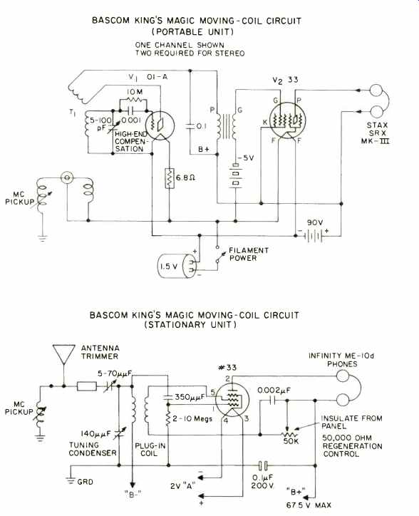
--BASCOM KINGS MAGIC MOVING-COIL CIRCUIT (PORTABLE UNIT) ONE CHANNEL SHOWN; TWO REQUIRED FOR STEREO
--BASCOM KINGS MAGIC MOVING-COIL CIRCUIT (STATIONARY UNIT)
-------
In the past many wonderful people out there in Audio Magazine's readership have written to Bascom requesting information and circuits.
Time and time again Bascom has remarked on his not being able to answer each letter personally.
I feel, at last, I might be able to close the information gap! While Mr. King was out of town, I removed and copied these designs from his safe. I hope they are okay. After all, what's a wife for, if she can't help out?! For those of you who make up these designs-Happy Audioing. For those with further questions, I'm sorry I don't know any answers.
For the rest-Happy First of April!!
--Nancy King, Santa Barbara, Cal.
Wideband Preamp Addenda
Dear Sir:
I have found an error in the parts list for the preamplifier circuit which I described in the February issue of Audio. By mistake, I overspecified the value of R3 in the input frequency compensation network by a factor of 10. This resistor should be 39 ohms rather than the published value of 390 ohms. If the incorrect value of R3 is used, a potential high -frequency instability problem could exist. This will manifest itself as a loud pop when the preamplifier is switched into and out of the phono mode.
Since the low TIM power amplifier was written, I have found that it is desirable to move the location of the lead compensation in the circuit from the feedback network to the forward path. This is accomplished by removing R33 and C10 from the circuit.
A 0.001 microfarad capacitor should then be installed from the emitter of Q6 to the junction of R22 and C4. A capacitor of the same value should be installed from the emitter of Q7 to the junction of R23 and C5. These can easily be added to the rear of the circuit boards. This change will minimize the occurrence of any high -frequency instabilities caused by poor power supply decoupling, poor high -frequency grounding, etc. Having supervised many student projects involving amplifier construction, I am aware that these problems can exist. The solution is simple to install, and I recommend its incorporation into any amplifier built from the articles, even if no problems are known to exist.
Incidentally, the orange foil pattern under Fig. 5(a) in the preamp article was "flopped" over a horizontal line.
While the component placement was correct, several things do not register.
Figure 4(a) was flopped the same way.
The reference to the first part of the article on the power amp was missing from the second part, and I hope this does not confuse anyone who missed the first part in February, 1976.
--W. Marshall Leach; Georgia Ins. of Technology; Atlanta, Ga.
Old Radio Repairs
Dear Sir:
A friend at work showed me a copy of the January issue of Audio Magazine. I was particularly interested in the article about the E.H. Scott radios.
At the conclusion Mr. Stosich states, "Sadly, almost no service technician has the knowledge, experience, or patience to perform the kind of work required...to get these fine sets in perfect operation." I would like to provide some information which will help any readers interested in the Scott or any other antique radios.
I had heard about the E.H. Scott radios for years, and last summer I restored one for an antique dealer who had purchased it for $20.00. There are many people who collect and restore antique radios; I've been doing it for seven years now. The main authority on Scott radios is JW.F. Puett who publishes a newsletter about them entitled "The Classic Radio Newsletter." He also sells parts and schematics for these sets and has a book out called "Silver Ghosts" which sells for $10.00. I also sell schematics for just about any radio made between 1923 and 1950, plus having a few old type tubes for sale. The other parts needed to restore these radios are either still common, available in surplus outlets, or being remade. I have collected a good list of "sources" for these needs and will gladly pass along any information I have.
There are two major old radio publications. One is Radio Age, 1220 Meigs St., Augusta, GA 30904, which is $7.50 per year. The other is The Horn Speaker published at P.O. Box 12, Kleberg, TX 75145. Mr. Puett's address is Puett Electronics, P.O. Box 28572, Dallas, TX 75228.
Although I am only 20 years old, I find that many of these collectors are audio enthusiasts of another era, and I can relate to the many stories and praises of these radios of the past.
--Mark T. Oppat, 31800 Balmoral Dr., Livonia, Mich. 48154
(Source: Audio magazine; Apr. 1977 )
= = = =