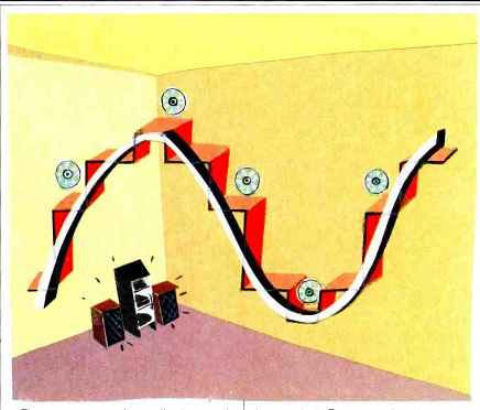
UP THE D/A STAIRCASE
All Compact Disc players have digita -to-analog converters, otherwise known as DACs or D/As. to convert the digital bitstream to an analog signal that analog preamplifiers, power amps and speakers can process. Eventually that will change:
CD players will output their information, still in digital form, directly to your all-digital stereo system. The analog signal that our ears require will not appear until the last possible moment, at the loudspeaker.
Sure, some CD players today have digital outputs, but they usually just feed bits to a box which has a D/A in it.
So far there's not much else to accept that output (though at least two integrated amps, Luxman's LV-109 and Kenwood's KA-3300D, have built-in D/A converters and digital inputs). But wherever the D/A is located now or in the future, it has to be someplace.
Not a single one of the bits flying off a disc at a rate of 1.4 million per second escapes the system without passing through the D/A. It is thus an important component in a digital audio system. Let's check out the basic designs for D/A converters and tackle a true fisticuffs-generating question: Should a good CD player have one D/A or two? The digital-to-analog converter is one of the hardest working components in a Compact Disc player. The pickup reads the channel bits from a disc, and they are demodulated. The audio data is separated from the control data; errors are detected, then corrected or concealed. The fast-moving audio bit stream is then fed to the D/A converter, which must produce an analog voltage corresponding to each digital audio sample. (In CD and DAT, each sample is expressed as a 16-bit word.) The sample voltages ultimately create two analog waveforms, one for each stereo channel.
The analog signal output from the D/A is equivalent to the signal appearing at the output of the sample-and-hold circuit on the recording side of the chain. Specifically, it's a pulse-amplitude-modulation waveform, easily spotted by its staircase appearance.
Also, you may recall that a filter is required, to remove unwanted supersonic frequencies (manifested as the stair case's sharp edges) from the D/A's output.
There are several excellent ways to accomplish D/A conversion. Designs that use resistor-ladder networks (Fig. 1) are classics. used widely in many CD players. The reference voltage source produces a voltage along the ladder, which is converted to a current by the resistors. Each successive rung of the ladder taps off half as much current as the preceding rung, corresponding to the binary value of the bits in the digital word. The bits of the word are used to open and close switches, turning their appropriate currents on and off. For example, a word with all zeros would keep the switches open, and no current would flow. A word with all ones would close all the switches, and maximum current would flow. The output current, proportional to the value represented by the input binary word, is then converted to a voltage, completing the D/A process.
Other D/As differ significantly in de sign but accomplish the same task. For example. an integrating D/A passes current at a constant rate but does so for a variable period of time per sample. The time period is controlled by the digital input, as shown in Fig. 2. A small digital value yields a small amount of time for current flow, where as a large value produces a longer time period. By measuring the amount of current which has flowed, and converting that current to a voltage, we come up with a voltage which corresponds to the input word. In practice, to achieve conversion speed without sacrificing accuracy, two current sources are used. The current sources have a precise ratio of 256:1, corresponding to the ratio between the values represented by the eight most significant bits of the input word and the eight least significant bits. The larger current source is controlled by the eight most significant bits and the smaller source by the eight least significant bits.
Another D/A technique, called dynamic element matching (DEM), uses the principle of current adding (Fig. 3).
A series of current sources with binary-weighted values are selectively summed, with the value of each bit controlling one source. When the result is summed and converted to a voltage, the D/A process is completed. In practice, an accurate current source is obtained by dividing a reference current source with a pair of resistors, then averaging their outputs with a pair of switches and capacitors. By cascading these or other types of current-dividing stages, a binary-weighted series of currents can be obtained. Their selected summation accomplishes the task of conversion. A DEM converter is cost-efficient because it requires no calibration.
Sony's engineers like the integrating D/A method and often use it in their CD players. Philips engineers, on the other hand, prefer the DEM design, so many Philips-made players (such as Magnavox units) employ this technique.
Whichever method is employed, the 16 -bit D/A converters in most players do not pose major design problems.
Yet there is one problem that seems insoluble. The output from any D/A is a pulse-amplitude staircase. (In practice, a sample-and -hold circuit is usually inserted to prevent switching glitches from leaving the D/A.) The du ration of each impulse in the output staircase wave is equal to the duration of a sampling period. Reconstruction at the low-pass filter, however, theoretically requires impulses of infinitely short duration. But infinitely short impulses are impossible to achieve be cause they would, among other things, require infinitely large current flow. Due to the finite duration of the output impulses, a filtering effect occurs in which the amplitude response gradually falls to zero at the sampling frequency, as shown in Fig. 4. This is because the frequency response is the Fourier transform of the sample period.
A plot of this transform takes the shape of the curve labeled (sin x)/x in the figure.
As a result, supersonic frequencies are partly attenuated, but so are the highest audio frequencies, which are rolled off by about 4 dB per octave.
(Oversampling reduces the loss only slightly.) This is known as aperture error. To minimize this high -frequency loss, the impulses can be narrowed to more closely match the duration of the original sample width. Shorter pulses produce a different Fourier transform and a flatter frequency characteristic for the pulse amplitude signal, as shown in Fig. 5. Fortunately, circuit de signers recognize the problem of aperture error and are able to compensate for its effects with a complementary high-frequency boost in the output conversion stages.
One issue over which circuit designers (or at least their company's accountants) disagree is the number of D/As to use in a CD player. Until all-digital systems become common place, and CD players omit D/As altogether, they can have either one or two of them.

Fig. 1 In a D/A converter which employs a resistor -ladder network, digital
switches control current flow in proportion to the signal value encoded in
each sample's bits.
Fig. 2 In an integrating D/A converter, the bits of the sample control the time during which current flows, and hence the total current per sample.
Fig. 3 In a dynamic element matching D/A, which uses the principle of current -adding, binary -weighted current sources are switched in and out by the bits in the sample, and the currents are summed together.
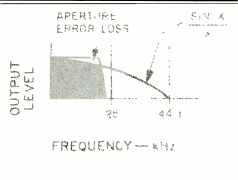
Fig. 4-The finite duration of output pulses causes aperture error, a roll
-off that reaches zero at the sampling frequency, and causes losses in the
audio band as well.
At first glance, two D/As might appear necessary. Since Compact Disc is a stereo playback medium, two audio channels are reproduced. As Fig. 6 indicates, the digital data stream can be de-multiplexed to left and right channels and fed to two D/As, resulting in two audio outputs. However, strictly for reasons of cost, most players em ploy one D/A, as shown in Fig. 7. The multiplexed data of the two audio channels goes to this single D/A, which must operate twice as fast as dual D/As. Only after D/A conversion is per formed is the data separated into left and right channels.
Although the results of each conversion method are apparently identical, small differences are introduced. Specifically, the single D/A design creates several anomalies in the signal. While the data bits from different channels are easily split apart in the dual D/A design, the interleaved segments of analog voltages produced from single D/A designs are not so easily separated. A switch must be used to route those pieces of waveform (at a rate of 88,200 per second) to the correct out put channel. There is a chance that the switch will cause distortion as it flips back and forth.
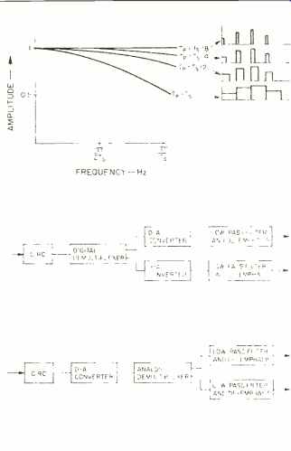
Fig. 5: Aperture-error roll-off decreases with shorter pulse durations (shown
at right).
Aperture is calculated as Tp divided by Ts, where Tp equals pulse duration and Ts equals sample period.
Fig. 6: Signal path with dual D/A converters.
Fig. 7: Signal path with single D/A. In some players, an 11.34-µS delay line in the earlier channel (not shown) is used to maintain synchrony.
In addition, the single D/A design introduces a slight time difference (11.34 µS) between the two audio channels. In a dual D/A design, the de-multiplexed data appears at the two converters simultaneously, exactly as it appeared at the A/D converters of the digital recorder. The output analog channels are thus exactly in phase that is, exactly matched in time. In a single D/A design, one output channel must wait for the other channel's sample to be converted. Therefore, it is always one sample behind, unless it incorporates a delay line that's just long enough to hold the leading sample until the trailing sample is able to catch up to it.
The 11.349s interchannel difference produced by a single D/A design is equivalent to a 0.1-inch difference in the distance from two stereo speakers to a listener. Theoretically this doesn't do stereo imaging any good, but in practice it's harmless. What's not harmless is the effect the time offset can have on stereo broadcasting. For example, cancellation could result in high -frequency roll -off in the L + R component, and reinforcement of the L - R component. Monophonic reproduction from a single-D/A CD player would produce the same high-frequency roll -off. The interchannel difference in a single D/A design can be partly compensated for, but this is difficult to achieve over the entire frequency range. Dual D/A designs avoid all of these switching -distortion and delay liabilities.
Unfortunately, not everything is sunny in dual D/A land. A pair of converter chips might mis-track due to fluctuations in their reference voltages or anomalies in the chips themselves; the result could again be phase error.
Some manufacturers have solved both problems by offering dual D/A converters on a single chip, a nearly ideal solution. Philips, for example, has gone this route in the dual D/A chip used in their new 16 -bit, four-times-oversampling chip set.
Until the all-digital audio system makes its debut, D/A converters will continue to provide the crucial inter face between digital and analog parts of an audio system. Here's one trend you can watch for: The D/A converter will be pushed farther and farther downstream as more and more of the components in the audio chain go digital. Eventually, pulse-width-modulation power amplifiers may alleviate the need for a D/A altogether. But that's another story.
(adapted from Audio magazine, April 1987)
Also see: Digital Domain (Mar. 1987)
= = = =