MANUFACTURER'S SPECIFICATIONS:
Frequency Response: 30 Hz to 30 kHz @15 ips, 30Hzto25 kHz @7 ½ ips.
Harmonic Distortion: 0.8 percent.
S/N Ratio: 60 dB.
Separation: 50 dB.
Input Sensitivity: Mike, 0.25 mV; Line, 60 mV at 150 kilohms.
Output Level: Line, 420 mV; headphone, 60 mV @ 8 ohms.
Wow and Flutter: 0.018 percent W_rms at 15 ips; 0.03 percent W_rms at 7 1/2 ips.
Speed: Accuracy ±0.1 percent; fluctuation, 0.05 percent max.
Fast Forward & Rewind: 150 seconds for 2500 feet.
Dimensions: 18 in. (45.7 cm) W x 17 1/2 in. (44.5 cm) H x 10 1/8 in. (25.7 cm) D.
Weight: 51 lbs. (23.1 kg).
Price: $1500.00.
=== === === ===
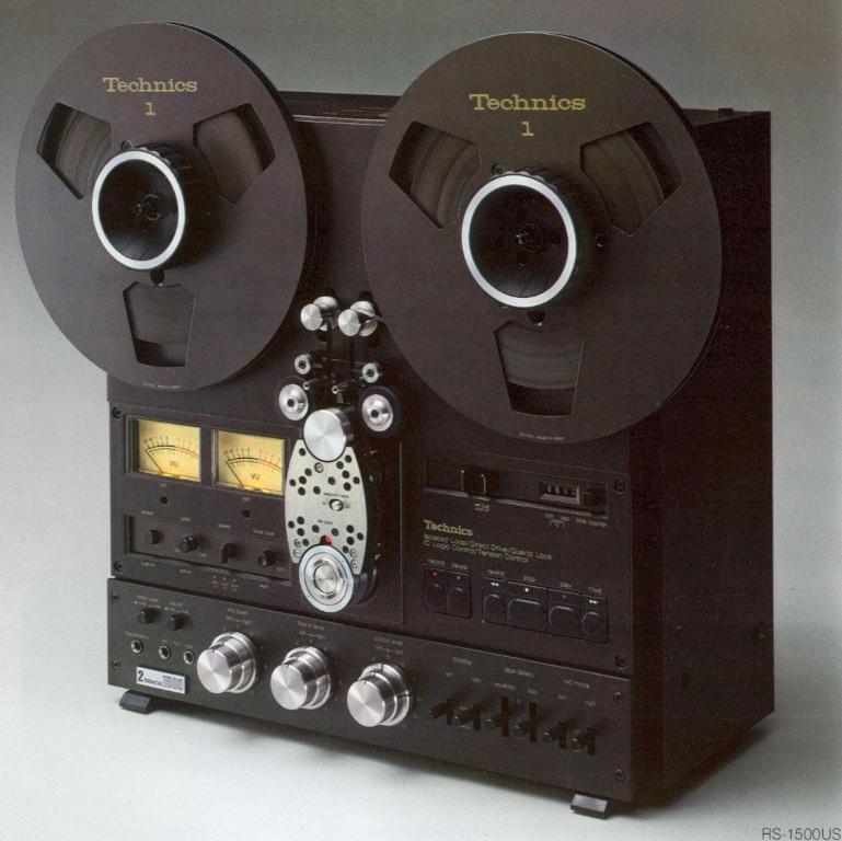
The Technics RS-1500US open-reel tape deck provides features and a level of performance that should be of interest to serious audiophiles and budding professionals. The front 'lane! of the deck, which can be operated either vertically or horizontally, is dark brown with gold lettering. The unit can handle up to 10 1/4-inch reels and operates at 3 3/4, 7 1/2 and 15 ips. At the top of the closed-loop drive system are the two air-damped tension rollers. Immediately below are the tape-position markers, and then two tape guides. Of particular interest is the single, large-diameter, 1.3 inch (33 mm), capstan with pinch rollers on each side. This direct drive capstan rotates at a very low rate, just 3.6 revolutions per second for 15 ips tape speed. The capstan motor and its speed-dependent frequency generator are part of a phase locked servo loop. The basic time/speed reference is a quartz crystal operating at about 4 MHz, which is divided down for the capstan speed reference. The phase locking provides tight, responsive control, and the crystal ensures accurate speed. With the tape being metered in and out of the head assembly by the single capstan, there is substantially complete isolation from external tape motion effects. The tape first passes over the 1/4-track playback head and then the 1/2-track erase head. The turn-around idler at the bottom incorporates helpful editing marks and an inner movable reference to facilitate moving the tape from the center of either playback head exactly to the nearest tape position marker. After the idler, the tape passes the 1/2-track record and playback heads before being fed out by the capstan. A switch on the face of the head assembly selects 1/4- or 1/2-track playback. The open construction permits very easy cleaning and demagnetization when needed. To the right is the cue control which can be used for editing or monitoring during high-speed winding, and the real-time minute-second counter, which is scaled for 15 ips.
Below are the tape-motion switches, featuring a light touch, and LED indicators for Play, Record and Pause. The IC logic control permits switching between any desired functions with the exception that the unit will not go into Record from FFWD or RWD unless Record and Play are held down as the tape comes to a stop. Pause will stop the tape in Play, but sensibly its status light will not go on unless the pause is made in Record. In that case, recording will resume simply by pushing Play. Flying-start recording is easily accomplished by holding in Play and pushing Record. Below the good-sized VU meters on the left are the power switch, the pitch control which is pulled out to operate, the speed selector, and the timer-start switch. In the bottommost section to the left is a meter scale to select either +3 (normal) or +6 VU for the maximum reading. The meters have the +6 VU scale in smaller print below the regular markings. Just to the right is the mike attenuator switch which can insert a very useful 20 dB reduction of the output from high-level mikes.
The phone jack mike inputs are below next to the headphone jack, which has its level controlled by the output pot.
From left to right are the mike, line input and line output dual-section pots which are friction clutched to permit channel level adjustments individually or simultaneously as desired, a worthwhile feature. The mike and line inputs, which can be mixed, have helpful settable marker rings. The output level control has a reference marker dot for a zero VU indication for a tape flux density of. 185 nWb/m (nano Webers per meter). Lever switches to the right provide source or tape monitor selection for each channel, three settings each of record equalizations and bias, and record mode preset for each channel.
End pieces attached to the metal frame are made of particle board and the back is hardboard. Line input and output connections are made with phono jacks, all nicely paralleled. Also on the back are an a.c. convenience outlet and sockets for a remote control and for 24 V d.c. power, permitting operation from storage batteries, which could be very handy at a remote location. A lock plate prevents switching between power modes accidentally. Removal of the back cover revealed the large-diameter construction of the low-speed direct-drive capstan motor. Circuit cards had components neatly identified, and board soldering was excellent. Access to adjustments appeared to be somewhat difficult, but further disassembly was not attempted to verify this assessment.
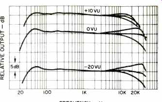
Fig. 1-Record/playback response @ 15 ips with minimum bias and three equalization
settings.
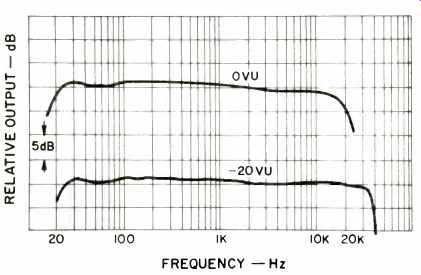
Fig. 2-Record/playback response @ 7 1/2 ips with minimum bias and minimum
equalization boost.
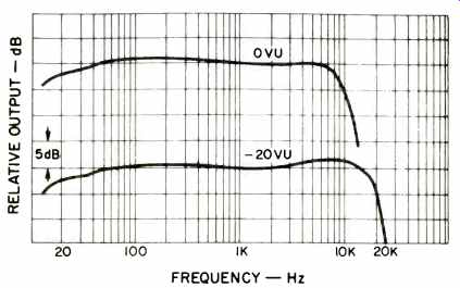
Fig. 3-Record/playback response @ 3 3/4 ips with minimum bias and medium equalization
boost.
Performance
Playback responses at both 7 1/2 and 15 ips were within 1.5 dB with slightly greater deviation at the lowest frequencies.
The meter indications to the specified 185 nWb/m flux level were within 0.2 VU for both channels with the output pots set to the marker dot, within possible errors in the test tape itself. A pink-noise source and a third-octave real-time analyzer were used to check the machine's basic performance with a number of tapes. While observing the playback, the EQ (equalization) and bias switches were operated to find the best combination for all three tape speeds. Record/ playback responses were excellent for all tapes tried, and Scotch 206, TDK Audua, Memorex Quantum, Ampex 456 Grand Master, and Maxell UD were used for more detailed testing. At 15 ips, the response was within 3 dB from 28 Hz to 45 kHz or wider for both Scotch 206 and Memorex Quantum at levels up to 0 VU! Response with the Scotch 206 at +10 VU extended from 30 Hz to 24 kHz, a good demonstration of the excellent headroom (Fig. 1). Responses were plotted with the Scotch tape with the three EQ settings and with the Memorex tape with the three bias positions. Responses were also taken at 7 1/2 and 3 3/4 ips with the Scotch 206 tape (Figs. 2 & 3). At 0 VU, results were 18 Hz to 17 kHz and 16 Hz to 9 kHz, respectively. At -20 VU, the high-frequency end shifted out notably to 35 kHz for 7 1/2 and to 19 kHz for 33/4 ips.
Measurements of the third harmonic distortion generated in the record/playback process used a 1-kHz signal with a record level from -10 to +10 VU for 15 and 7 1/2 ips with Scotch 206, TDK Audua and Maxell UD (Fig. 5). At 15 ips, the distortion was 0.18 percent or less at 0 VU, and 0.8 percent (the specification limit) or less at +6 VU. The distortion level was less than 2.2 percent at +10 VU, and was down to 0.025 percent or less at -8 VU. At 7 1/2 and 3 3/4 ips the distortion figures were, respectively, 1.4 and 2.8 times the 15 ips results at most record levels. The 3 3/4 ips data was obtained for Scotch 206 only. Distortion was also measured with test frequencies from 20 Hz to 15 kHz at record levels of 0 and -10 VU. As the distortion levels were too low at -10 VU to obtain valid data at all frequencies and test speeds, the data reported here is from 0 -VU tests only. Because of the unit's very wide frequency response, it was possible to measure third harmonics with test frequencies as high as 15 kHz for 15 and 7 1/2 ips and 12 kHz for 3 3/4 ips (See Fig. 6). In all of the distortion tests made, there was very little evidence of other harmonics in the output.
The A-weighted signal-to-noise ratio for two tapes and 7 1/2 and 15 ips ranged from 63.2 to 66.4 dBA with the manufacturer's specified 185 nWb/m +6 reference. Even at 3 3/4 ips the figure obtained with Scotch 206 was 2.7 dBA above the specified 60 dBA. A two percent distortion level seems proper for the VU meters used, which would provide ratios of 66.8 to 70.0 dBA for 15 and 7 1/2 ips, and 62.0 dBA for 3 3/4 ips. Separation between tracks was at least 58 dB with a +6 VU test signal, easily better than the specified 50 dB. Erasure of the same signal was 63 to 67 dB down, depending on tape speed. Input sensitivities were 0.23 mV for mike and 59 mV for line, both slightly better than the specifications.
Playback of 0 VU record was exactly to spec on the right channel, 0.8 dB low on the left channel. Maximum output levels were 690 mV (L) and 735 mV (R) for the same record level. The headphone drive across 8 ohms was 67 mV, greater than specified. The meter response to a 300 -millisecond burst was to VU standards, and the frequency response was down 3 dB at 27 Hz and 56 kHz. Meter scale readings were within 0.2 dB at all levels, and tracking of the channel pots was excellent.
To get a good collection of data on various speed characteristics of this excellent deck, a very stable 3160 Hz tone was recorded the length of reels of Scotch 206 and Ampex 456.
The reels were then flipped and played back in opposite direction to maximize any possible errors caused by varying tape tension. The meter terminals of the flutter and drift meter were fed to a calibrated strip-chart recorder. At 15 ips the flutter was nominally 0.025 percent DIN weighted peak throughout the entire tape run, with values as low as 0.005 percent and occasional maximums of 0.04 percent. At 7 1/2 ips, typical figures were 0.04 percent Wtd peak, with lows of 0.01 percent and occasional maximums around 0.05 percent. The manufacturer's figures of 0.018 percent Wrms for 15 ips and 0.03 per Wrms for 7 1/2 appear to be completely justified. Two other open-reel machines were measured for flutter at 7 1/2 ips for comparison. One had demonstrated superior low-flutter performance in the past, but it did not quite match the Technics deck. The second unit was obviously inferior in this comparison, although its specifications would usually be given a very high rating. To check modulation noise, a 1.0 kHz signal was recorded at 0 VU, and the narrow-band spectrum of the playback was plotted from 500 to 1500 Hz (Fig. 7). There was an evident reduction of sideband levels with Scotch 206 as tape speed was increased. On the low-flutter "other" machine, the modulation noise was generally comparable. Then, Ampex 456 was used with the Technics at 7 1/2 ips (See Fig. 8), and the reduction in modulation noise with this mastering tape was quite obvious.
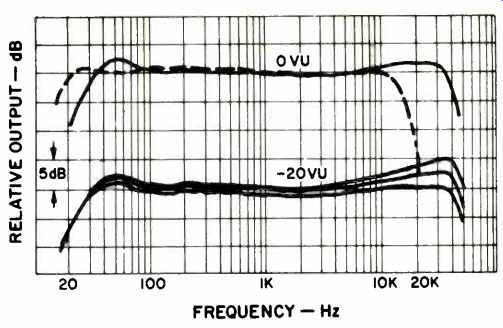
Fig. 4--Record/playback response with Memorex Quantum tape with the three
bias settings at -20 VU @ 15 ips; upper trace @ 7 1/2 at 0 VU at the medium
bias setting.
Speed fluctuations were measured by playing the 3160-Hz tapes and feeding the strip-chart recorder as described above. The counter reading on playback was exactly 3160 Hz throughout the entire length of tape, and the plotted drift showed minute variations around a constant speed (frequency). The conclusion was drawn that the unit was exhibiting outstanding tape tension control and speed stability. At both 15 and 7 1/2 ips, the speed variations were within 0.05 percent of a nominal reference, with 15 ips slightly better (Fig. 9).There was no measurable variation in tape speed with line power changes from 90 to 130 V. There was no external method refined enough to prove the exact tape speed, but according to the built-in strobe lamp and the marks on the edge of the turn-around idler, the tape was running a miniscule 0.015 percent fast. With the variable pitch control pulled out, all three tape speeds could be varied from 6.1 percent slow to 7.3 percent fast. Recorder starts were tested by using the drift circuit as a speed detector, with its output fed to an X-Y recorder. Overshoot in the drift circuit itself from the suddenly applied signal obscured the earlier conditions, but the plots for 15 and 7 1/2 showed the relatively short time required to obtain very steady tape motion. Improved instrumentation would be required to secure more complete verification of the recorder's excellent speed characteristics. Rewind for a 2500-foot 10 1/2-inch reel was 116 seconds, well within the specification. Readings taken of the counter at timed intervals during fast wind proved that with either 7 1/2 or 10 1/2-inch reels the tape speed was constant, showing excellent control of winding tension. The noise levels from the machine measured at one foot were 31 dBA at 15 ips, 28 dBA at 7 1/2 ips and 25 dBA at 3 3/4, ips. At a few feet in a reasonably dead room, all readings would be less than 20 dBA; excellent low-noise operation.
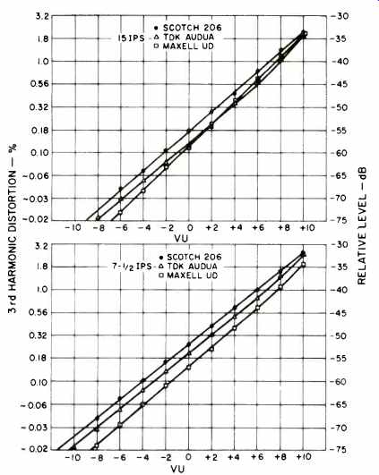
Fig. 5-Third harmonic distortion vs. record level 15 ips (top) and 7 1/2 ips
(lower) with Scotch 206, TDK Audua, and Maxell UD tapes.
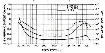
Fig. 6-Third harmonic distortion vs. frequency at 0 VU with Scotch tape @
3 3/4, 7 1/2, and 15 ips.
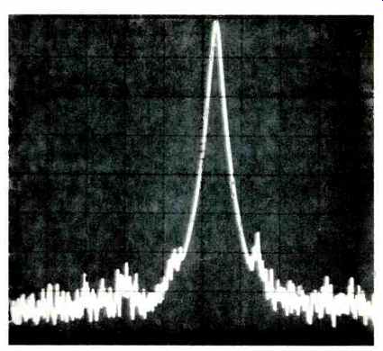
Fig. 7-Modulation noise with the Scotch 206 tape @ 15 ips on a 1 kHz signal
recorded at 0 VU. The scope settings are: horizontal, 100 Hz per division to
1 kHz; vertical, 10 dB per division to 80 dB.
In-Use Tests
Threading the machine was much easier than might be judged looking at the collection of rollers and idlers, as the tape loop falls naturally around the head assembly. The feather-touch tape motion switches and the associated logic performed without error, and a thrown loop or stretched tape was never achieved in many attempts. Longer spindles on the reel turntables would aid putting on reels, particularly when the machine is vertical. The 10 1/2-inch-reel adapters caused a bit of fumbling as they fit into the outside of the reels, and then this assembly had to be placed on the spindle. All of the pot knobs are of good size and have an attractive appearance. The friction clutching worked very well in keeping sections together or slipping when desired, and the marker rings would benefit from a little more knurling.
The meters have good visibility, and it was easy to set levels on both channels. Although the unit has excellent headroom, particularly at 15 ips, some form of peak indication would have been helpful. The machine was operated for many hours at all three speeds, switching back and forth from source to tape monitoring. Minor modifications to the sound could be detected only at 3 3/4 ips. Superior speed characteristics, especially the low flutter, and the extended response at higher levels were judged to be major factors in providing the excellent sonic results. Switching between source and tape did not generate clicks in the recording that could be detected. Record on/off clicks could be heard by listening carefully, but the actual level was down to that of tape noise. A brief check was made of the operation of the 1/2-track playback head.
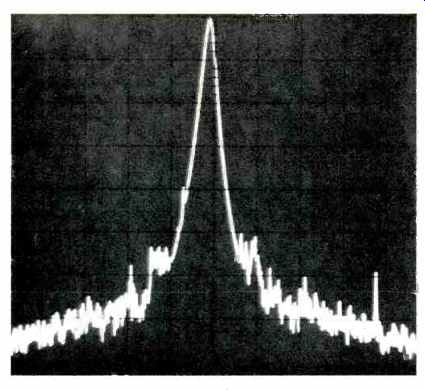
Fig. 8-Modulation noise with the Ampex 456 tape @ 7 1/2 ips on a 1 kHz signal
recorderd at 0 VU, with horizontal readings to 1 kHz in 100 Hz per division;
vertical to 80 dB at 10 dB per division.
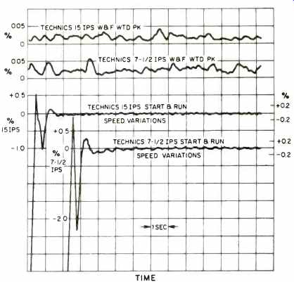
Fig. 9-Speed variations and wow & flutter at 7 1/2 and 15 ips with the
Technics RS-150005 reel to reel tape deck.
The EQ switch provided maximum boost when it was down in position 1, minimum boost when it was up in position 3. The bias switch provided minimum bias when it was down, maximum bias when it was up. It seems that it would be more logical to most operators if lifting the levers up would cause the high frequency response to go up, the reverse of what happens with the present scheme. Comments cannot be made on the instruction book coverage in this or other areas, as it is still in process. The unit operated well in timer start, in Record if the record preset switches were on.
The performance of the Technics RS-15000S deck leaves substantially nothing to be desired by serious audiophiles.
The unit is even capable of recording the carrier channel of CD-4 systems right out to 45 kHz. It must be noted that the excellent signal-to-noise ratios are achieved without Dolby circuitry. For the professional, the major limitations would actually be in the area of input/output interfacing.
Balanced line in/out could be added at relatively small expense, however, so budding professionals should consider this recorder quite competitive to other somewhat more expensive machines. Hopefully, Technics will add peak indicators to the benefit of all users.
H. A. Roberson
=================
The Measurement of Tape Recorder Distortion
A plot of percentage distortion vs. output level for a typical amplifier can be flat over a considerable range with perhaps some rise at the lowest levels, and at maximum output the distortion figures increase sharply. Many plots of tape recorder distortion in the past have looked generally similar, but were in error at lowest levels because of noise effects.
The fundamental-rejection type of harmonic distortion meter needs and has a wide bandwidth to measure the energy from all harmonics. This approach works well with amplifiers which have low noise. Tape recorders, relatively speaking, have high noise, and the result is that the measured "distortion" at lower levels is determined by the noise, not the harmonics.

To get accurate distortion figures in such a case, it is necessary to reduce the effect of the noise so that the discretes stand out. It might be noted here that your ears are regularly detecting signals below the overall, broadband sound level.
Since April, 1975, Audio has been reporting recorder distortion figures that have been obtained with a spectrum analyzer. By settings its i.f. bandwidth to 10 Hz and scanning slowly, it is possible to display harmonics at levels considerably below 0 VU. Many had come to believe that recorders had distortion that was a minimum of perhaps 0.5 to 1.5 percent. The experience of making such tests for two years has shown that the distortion can be as low as 0.1 percent for recording at 0 VU, and possibly less than 0.01 percent at -10 VU. Actually, the distortion level is more directly related to the resultant flux level on the tape, but these figures give an idea of what might be expected from a high-performance recorder/tape combination.
The distortion products of the magnetic record/playback process normally consist almost exclusively of third harmonics. Any second harmonic is probably the result of some sort of maintenance problem: a magnetized head, a leaky coupling capacitor, or other defect. Higher odd harmonics, particularly fifth, may show up at higher record levels, but are usually of low amplitude compared to that of third. For the majority of operating conditions, the level of the third harmonic is essentially equivalent to the total harmonic distortion level. If the percentage distortion figures are plotted on a logarithmic scale against a linear scale for record (or flux) level in VU (or relative dB), the resultant curve is a straight line. The percentage distortion usually changes about ten to one, or 20 dB, for each 10 dB change in record level. This two-to-one relationship holds all the way from the noise limit at the lower end to perhaps 10 dB or more above 0 VU. Deviations from the nominal two-to-one slope can be caused by the contributions from lower-level fifth-order distortion products.
In the accompanying figure of a possible recorder/tape characteristic, the third harmonic distortion is about 0.5 percent at 0 VU and reaches 3 percent at +8 VU. At -10 VU, distortion is down to 0.05 percent, just one-tenth that at 0 VU. Probable figures for distortion at levels below -10 VU can be obtained by extending the straight line and filling in the grid. To date all of the evidence indicates that the function remains straight down to the lowest levels. There is less data on very high levels, due to a general reluctance to burn out meters. It can be stated, however, that the measurements at least suggest that the straight-line character is maintained at least part way into saturation and self erasure. The evidence to date also supports a tentative conclusion that the slope determined for a test frequency such as 1.0 kHz applies to other frequencies for the same recorder/tape combination. In other words, the distortion figures for another frequency such as 200 Hz can be determined over a range of levels by applying the slope from the 1.0 kHz level data to the distortion level shown for 200 Hz on the distortion vs. frequency plot.
-Howard A. Roberson
=================
(Source: Audio magazine, May 1977; Howard A. Roberson)
Also see: Teac X-20R Open-Reel Recorder (Mar. 1982)
Technics Model RS-616 Cassette Deck (Feb. 1979)
= = = =