Author: MIKE ERGO
[Mike Ergo is an automotive electronics consultant, trainer, and writer. He belongs to the Automotive Service Association and the Vehicular Technology Society of Electrical Engineers.]
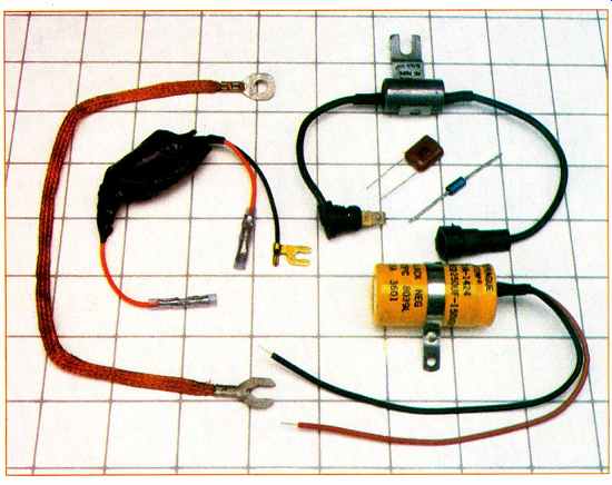
--------- Grounding straps, diodes, capacitors and filters, such as these,
can help reduce some of the noise problems found in car stereos.
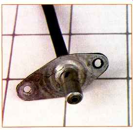
---------- One should measure the resistance of a windshield antenna
at the point where the antenna lead from the radio is plugged into it. Look
for a jack like this one at the bottom of the windshield cowling.
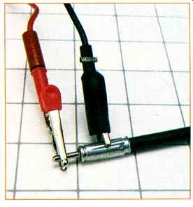
----------- The resistance measured between an antenna cable's center
pin and shield should be at least 10 megohms and may well be greater.
Can you imagine what it would be like to be the only Dallas Cowboy fan sitting in R.F.K. Stadium cheering the Cowboys on as they and the Redskins slug it out? To say you were in a hostile environment would be, to say the least, an understatement. Well, that's exactly the predicament a sound system is in when it's installed in a car. One of the biggest challenges for engineers and installers is how to create sound systems that will operate satisfactorily, let alone in superior fashion, when subjected to all the variables associated with an auto motive environment.
An automotive sound system is subjected to extreme temperature ranges, constant vibration, moisture, and dirt, and the antenna system faces environ mental hazards (such as corrosion) and vandalism. Moreover, the car is constantly moving in relation to the broadcast tower, giving rise to such phenomena as multipath and dead spots. To top it all off, this delicate system has to operate in close proximity to an a.c. generator (the alternator) and a high-voltage spark machine (the ignition system). As you can see, it's no wonder pops, buzzes, crackles, and whines creep into the system from time to time.
However dismal this scenario may seem, there is hope of enjoying a car sound system that is free of annoying disturbances. But before we get to the remedies, let's examine the different types of noise that your sound system is subjected to.
There are two different types of noise: Those that are a result of conditions inside your car, and those that are created by outside factors. The latter group includes such things as lightning, power lines, radar, or broadcast installations. For the most part, there is not much you can do about these disturbances other than changing your course of travel. Also included in this latter category are multipath and dead spots, and they generate numerous consumer complaints. They are often mistaken for noises generated inside the car or as defects in the sound system itself. Although there is very little the consumer can do to prevent these listening disturbances, it is important to have a good understanding of both.
To understand multipath and dead spots, a quick review of FM radio is necessary. Commercial FM (frequency modulation) broadcast is from 88.1 to 107.9 MHz. In this frequency range, FM radio waves tend to behave very much like light waves. Unlike AM waves, FM waves do not bend, and FM reception is considered to be line-of-sight transmission. Therefore, the range of FM is usually only 25 to 50 miles, depending on the terrain.
Like light waves, FM waves can be blocked or shadowed by objects that get between your car's antenna and the radio station's broadcast antenna;
these include buildings, poles, towers, and many other structures (Fig. 1). As you travel down a street or highway, you pass through these signal shadows. Since you are travelling rather quickly in most cases, and the wave length of an FM signal is short, the shadow appears only momentarily usually for a fraction of a second. however, during that time your radio experiences a loss of signal and hence has no signal to amplify. What occurs is an audio disturbance referred to as picket-fencing, heard as a high-frequency flutter as the signal comes and goes.
This disturbance is often mistaken for a problem in the sound system or a noise being generated in the car, but it is actually due to a loss of signal; it is not the fault of the radio or radio station. Unfortunately, as I've said, there is nothing you can do to prevent this disturbance.
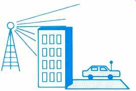
Fig. 1--Picket-fencing is caused by brief signal interruptions that occur
as a car moves through the dead spots where buildings and other objects block
the radio signal.
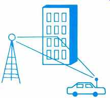
Fig. 2--Signal reflections following different path lengths create multipath
distortion in FM.
A second external phenomenon associated with FM broadcasts is multi-path. This annoying listening disturbance is also often mistaken for a defective sound-system component or a car-generated noise. It arises when FM radio waves, acting like light waves, reflect off certain objects. Again buildings, poles, and towers are but a few of the objects that can be the culprits.
These reflected waves are received at the car's antenna a split second after the original radio wave arrives (Fig. 2).
Receiving two identical waves only slightly out of phase can cause very audible distortion, as though the radio were tuned slightly off-station, or drifting. It may also manifest itself as a garbled sound or as a crackling in the speakers. This same phenomenon is the cause of "ghosts" on television.
While neither picket-fencing nor multipath can be prevented, their effects can be minimized by switching to monophonic, reception, if your tuner al lows. Tuners with automatic high-blend thresholds which are low should suffer less audibly, as should those with diversity antenna-switching systems. A tuner with greater sensitivity would probably suffer less from picket-fencing, while one with a lower capture ratio and higher AM rejection should be less affected by multipath.
Now let's take a look at some internally generated noises. The most common noises in an automotive sound system are alternator whine, secondary ignition noise, switch pops, and solenoid and relay pops or ticks. One of the first steps in noise diagnosis and remedy is to determine as closely as possible where the noise is coming from. There are several clues you can use. For example, if the sound is a whining or slight buzzing that changes pitch when engine RPMs are increased, there's a good chance you are experiencing alternator whine. A ticking or popping sound that speeds up as engine RPMs increase is usually ignition noise, such as spark plug firing. A loud pop heard when you turn on such accessories as electric windows or electric seats is usually either a switch pop or a spike caused by energizing or de-energizing a relay or solenoid. (This latter phenomenon is caused by the sudden build-up or collapse of the magnetic field in a relay or solenoid coil, or in some other inductor.) Included among switch pops is a sound heard only when the turn signals are on, caused by the turn-signal flasher.
Another common source of noise is a buzzing or popping heard only when the horn is honked. This can be caused by the horn itself or by the relay that activates the horn.
Once we have a good idea where the noise is being generated, we must determine how it is entering our sound system. This step is vitally important, as it will determine the method or methods by which we try to suppress the noise.
We can divide noise into four main categories, based on where it enters the sound system. First are "frontway" noises, those that enter through the radio's antenna input. Second are "sideway" noises, which enter directly into the chassis, by radiation. Sideway noises are among the hardest types of car noise to eliminate. They are relatively rare now, but unfortunately they are growing more common, as radiation sources such as cellular phones, CD players, and digital clocks are in stalled in more car interiors.
The third category is "backway" noise, which comes through the 12-V power leads of the head unit or amplifier. Unlike noise that enters through the tuner's front end, noise riding on the 12-V lead is input directly to the amplifier stages, and is immediately amplified and heard. (Even though most car stereo components have input filtering, sometimes it is not adequate for all noise levels.) Ground loops are the fourth major path for noise entry. Ground loops exist where there is more than one ground path between the stereo system and the car battery's negative terminal. To the extent that these paths' impedances or resistances differ-and they always do--each will be at a different potential relative to the battery ground. This difference in potential causes a small current flow, the a.c. component of which is noise. Ground loops represent only a small proportion of noise problems in head units, but a fairly high proportion of noise problems in amplifiers, crossovers, and equalizers. Ground loops can often be eliminated, but there is very little you can do to filter a ground.
Now that we have taken a look at the different ways noise can enter a sound system, let's see how we can deter mine which way the noises are actually entering. This is simply a process of elimination. Start by unplugging the antenna from the radio. If the noise goes away, it was obviously coming in via the antenna input; if it doesn't, we need to investigate further. Another quick way to determine if the noise is entering in this way is to turn the system's volume all the way down. If the noise does not go away, it cannot be coming from the antenna input, as such noises are processed by the tuner front end and amplified as if they were radio signals. In that case, ground loops are the most likely cause.
A good way to check for noise radiation into the head unit (sideway noise) is to remove the radio from the dash. If the noise diminishes or changes pitch as the chassis is moved in and out, you probably are experiencing sideway noise. However, it is also possible for interference radiation to affect other components or signal cables and power wires.
Distinguishing between power-line (backway) and ground-loop noise en try can be a little more involved, and requires trying certain fixes which we will get into later. One thing to keep in mind is that noise coming in on the 12-V lead affects head units more commonly than ground-loop problems do, though the opposite is true for other components.
So far we have looked at the different types of noise, how they enter a sound system, and how we determine which way they are entering. Now it's time to start suppressing those annoying disturbances. Before we start put ting filters, chokes, and diodes all over the car, we must take a look at these devices and see how they work.
A capacitor, which is two conductors separated by an insulator, is often used to smooth or filter out a.c. signals.
To d.c. this filter looks like an open circuit, but to a.c. it looks like a short.
Thus, by putting a filter from a d.c. line to ground you can bypass all the un wanted a.c. to ground and leave the d.c. portion virtually untouched (Fig. 3). An inductor, or choke, works in just the opposite way. To d.c. a choke basically a coil of wire--is a short.
However, to a.c. a choke looks like a high resistance, and thus acts as an a.c. block (Fig. 4). By putting a choke and capacitor together we end up with a filter package (Fig. 5). A filter pack age not only blocks a.c. with the inductor, but also shorts the a.c. to ground with the capacitor-a double whammy.
Finally, we have diodes. These are semiconductor devices that allow current to travel in one direction only.
However, all diodes have a peak in verse voltage (PIV) at which they will start conducting in the opposite direction. This makes them especially useful for spike voltage suppression. By inserting a diode backwards (reverse biased) in a circuit-that is, with the an ode (+) to ground and the cathode (-) on the positive side-we can sup press noise-causing spikes, as shown in Fig. 6. (The cathode end of an actual diode is usually marked with a silver band.) A spike, like those generated by relays and solenoids, and by switch arcing, usually ranges from 50 to 100 V. This is usually enough to exceed the PIV of the diode and thus the spike is shunted to ground, leaving the d.c. (+12 V) portion unaffected.
Fig. 3-A capacitor can be used to shunt a.c. noise from the d.c. power line
to ground.
Fig. 4-An inductor, such as this choke coil, also blocks a.c. noise in the d.c. power line.
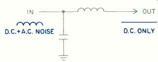
Fig. 5-An inductor and capacitor together make up a filter package.
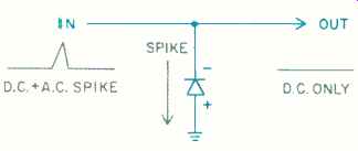
Fig. 6-A reverse-biased diode can shunt large a.c. spikes to ground.
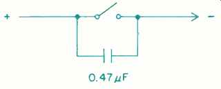
Fig. 7-Placing a capacitor across switch contacts can reduce pops and clicks
when the switch is operated.
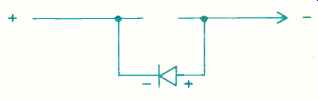
Fig. 8-If a switch operates a motor or other inductive load, a diode across
the switch may reduce noise.
We are now armed and ready. Let's look at some specific noises and how we can eliminate them. (Keep in mind that many sound system noises can be eliminated by a proper tuneup. Always make sure your car is tuned and running properly before attempting to eliminate such noises.) Start with frontway noises such as secondary ignition noise and alternator whine, which frequently come in via the antenna. This often indicates a poor antenna ground, so the first check is to make sure the antenna is grounded properly.
This can be done with an ohmmeter.
Corrosion at the mounting base or a broken braid inside the coaxial cable can cause poor grounding and thus introduce noise into a system. By measuring with an ohmmeter between the antenna base and a good ground, such as the negative battery post or the alternator housing, you can deter mine how well grounded the antenna is. You should measure less than 1 ohm. Next, check the radio end of the coax. Unplug the antenna lead-in from the radio and measure between the ground case and a good ground.
Again, the reading should be less than 1 ohm. This ensures that the ground braid of the antenna is not broken, and that the antenna's ground connection (usually its base) is making good con tact with the metal of the panel it is mounted on. (If it is not, corrosion or sound-deadening material beneath that panel may need to be scraped away.) Finally, check for a shorted coax by measuring between the lead in tip and coax ground. This reading should be 10 megohms or greater. If by chance your antenna is in the wind shield, the above checks still apply.
However, since there is no antenna base, the first check must be made at the windshield cowling where the antenna lead plugs in.
Having made sure that the antenna system is properly grounded, we now must try to suppress each individual noise. In the event of secondary ignition noise we should look for broken spark plug wires, a cracked or worn distributor cap, or a bad spark coil. A worn carbon ball inside a distributor cap can play havoc with a sound system. In older cars with points, pitted points can have the same effect.
Sometimes grease or carbon film coats the inside of the distributor cap, causing a crackling or frying sound. Simply cleaning the inside of the distributor cap can remedy the problem.
If our noise is a frontway switch pop we might try a 0.47-µF capacitor across the switch contacts (Fig. 7), or if the switch operates an inductive load (motor, solenoid, relay, etc.) we might put a spike-suppression diode (1N4001) across its terminals (Fig. 8).
If the diode has no effect, try a filter.
Keep in mind that there is no black magic involved in noise suppression. It is a series of educated trials and errors. When trying a filter, use several values of capacitance to see which one works best. Start with 0.47 µF, then try 0.1 or 500 µF. The bottom line is this: If it works, do it! If you still are experiencing frontway noise, make sure the car's hood is grounded properly to the car's frame by using either a flat, braided ground strap between the hood and firewall or a hood ground clip that makes good electrical ground when the hood is closed. Also make sure the radio or amplifier chassis is properly grounded.
Curing radiated (sideway) noise is, as mentioned above, difficult. Among the possible solutions are moving the affected component (easy for amplifiers and crossovers, but hard for in-dash head units), moving the noise source, and moving the wires connected to either the sound equipment or the noise source. If the problem is magnetic radiation being picked up by the tape heads, a mu-metal shield between the tape player and the noise source may help. Such shields are sold by some car stereo manufacturers, and may be available through lo cal dealers and installers.
Now let's take a look at some other noise problems which can enter as backway (power-line) noise or via ground loops. Alternator whine (which can also, as we've seen, enter as frontway noise via the antenna input) is one of the most common types. If your stereo consists of a single head unit with built-in amplifiers, this whine is most likely to be backway noise. Your best bet in curing this is to start with a filter package on the 12-V lines to the head unit. (If the unit has a separate unswitched line to keep its memory alive, or a separate line for night illumination, be sure to filter all of them.) Another possible cure is to put a 500-to-1,000-µF capacitor between the alternator's output line (usually a 12-gauge red or orange wire) and the alternator case.
As for switch pops, relay ticks, and turn-signal pops, the same fixes as de scribed above apply. Try combinations of filters and diodes. When trying to suppress particular components such as relays and switches, the rule of thumb is to always install the suppression devices as close to the source as possible. In other words, a capacitor installed across a switch is more effective when installed directly across the switch terminals than when installed in the wiring harness four inches from the switch.
Finally, we are left with the dilemma of ground loops. If you have separate components such as an equalizer or power amp, this is a more likely noise path than the 12-V line. Filter packages installed on the 12-V line are ineffective, since they filter the hot side and not the ground side of the circuit. Filters and diodes applied to each component may be effective, but they should be used as a last resort (and removed if they don't help-they sometimes can cause problems). The only way to eliminate ground loops is to find all the connections between the system and ground, and break all but one of them.
The more complex the system, the more potential grounding points it has.
Each component usually has both hot and ground power leads. Screws holding a component in place can also set up ground paths between the component's metal case and the car's body metal. The case may also accidentally contact nearby body parts, and cases that don't quite contact the body when the car is at rest may contact it when the car is moving, causing intermittent noise problems that are hard to track down. The shields of the signal cables between components act as ground paths between those components too.
And the antenna must be grounded for good radio reception. (Because of this, the antenna may sometimes serve as the one ground point for an entire sound system.) To break the extra ground points, try detaching the ground leads of the system components, one by one. (Do not, however, detach the amplifier's power ground, as this can cause the amplifier's ground current to be drawn through the signal cables, creating a fire hazard. If you wish to move the amplifier's power ground, make sure the system is off while you do so.) Assuming the system has other ground paths, it should still operate, and its noise level should drop. If the unit doesn't operate with its ground lead clipped, attach the ground wire to the nearest source of ground, making the wire as large in diameter and as short as possible (Fig. 9).
If clipping all ground leads still leaves a noise problem, check for physical grounds between component cases and the car, by direct contact or through fastening screws. If need be, detach and lift each component from the car, and see if the noise disappears or lessens. To cure such a physical grounding problem, you can insulate most components from the car by mounting them on wooden (or similar) boards and using separate screws to attach the boards to the car. In some cases, it may suffice to put insulating bushings between the component's chassis and its mounting screws. Insulating head units from the dash may prove to be difficult; insulating them from braces, ashtrays, ducts, and other under-dash metalwork is easier to accomplish.
If the extra grounds can't all be eliminated, reducing the difference in ground potentials may help. This can be done by grounding all components in the system together, with a separate ground wire or strap (Fig. 10). Always use 14-gauge (or heavier) wire or a braided ground strap for this purpose.
If this increases the noise, then disconnect the shields from the plugs at one end of each signal cable, so that the ground straps and signal cables will not combine to form new loops.
To review, there are several steps to keep in mind when attempting to eliminate automotive noises in your car's sound system. First determine the origin of the noise. Is it being generated outside the car by normal phenomena such as dead spots or multipath? If it is being generated within the automobile, is it the alternator, the ignition system, a switch, or a relay? After determining the origin, determine how the noise is getting into the system. Is it frontway, through the antenna, or backway, through the power leads? Or is it side way noise, or possibly ground loop interference? After investigating you can go to work. Remember filters and di odes work well for spikes. Chokes work well on power leads for alternator whine. Keep in mind that suppression components should be put as close to the source as possible. That is, for switch pops, put the filter on the switch itself. Finally, remember that trial and error are your best tools. Good luck and good listening!
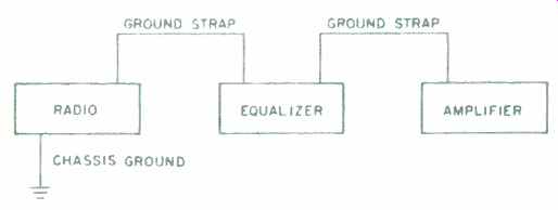
Fig. 9--Shortening the ground path by using the nearest possible ground
point may cure ground-loop noise.
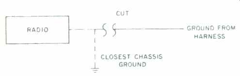
Fig. 10-Another way to reduce ground-loop problems is to tie components
together with a low-resistance wire or strap. This may necessitate clipping
the shields at one end of each signal cable.
(Author's Note: All the noise suppression devices mentioned in this article can be purchased at local electronics stores such as Radio Shack. Make sure that the values you pick are appropriate for automotive use, since the wrong values can create unsafe situations. Capacitor voltage ratings should be at least 50 working volts, and each filter package should be rated high enough to handle the current of the device it is filtering. Also, any component used under the hood should be adequately protected from the environment or packaged for external use, as metal-cased capacitors are. If you have questions, ask the salesperson at the electronics store, explaining what you intend to use the device for.)
(Source: Audio magazine, May 1987)
= = = =