MANUFACTURER'S SPECIFICATIONS:
AMPLIFIER SECTION
Power Output: 45 Watts per channel, RMS, at any frequency from 20 Hz to 20 kHz.
THD: Less than 0.5%. Power Bandwidth: Below 10 Hz to above 40 kHz.
IM Distortion: Less than 0.15% at rated output. All above referenced to 8 ohm loads, both channels driven. Damping Factor: 30 or better to below 20 Hz. Input Sensitivity: 1.5V. Hum and Noise: Better than 85 dB below rated output (unweighted). Frequency Response: From below 4 Hz to above 70 kHz ±0.5 dB.
PREAMPLIFIER SECTION
Frequency Response: From below 3 Hz to above 100 kHz +0.5 dB. THD: Less than 0.05% at 2 V. output, 20 Hz to 20 kHz. Hum and Noise: Low level, 65 dB below 2 V out at 10 mV input reference; high level, 80 dB below 2 V, volume control fully clockwise; residual, 90 dB below 2 V. Phono Overload: 90 mV. Tone Control Range: ±12 dB boost and cut (frequencies not stated).
FM TUNER SECTION
IHF Sensitivity: 1.8 µV. Ultimate S/N: 70 dB. THD: Mono, 0.5%; Stereo, 0.6%. Selectivity: Better than 50 dB. Image Rejection: 90 dB. I.F. Rejection: 90 dB. Spurious Response Rejection: 90 dB. AM Rejection: Better than 60 dB. Stereo FM Separation: 38 dB @ 1 kHz; 33 dB @ 100 Hz; 30 dB @ 10 kHz. 38 kHz suppression: Greater than dB.
TUNER SECTION
AM Loop Sensitivity: Better than 200 µV/ meter. Selectivity: 35 dB. Image Rejection: Better than 60 dB. I.F. Rejection: Better than 60 dB.
GENERAL SPECIFICATIONS
Dimensions: 17 1/2 in. W by 13 ¾ in. D by 4 ¾ in. H.
Weight: 29 lbs.
Price: $399.95
It's been a couple of years since the engineering department of Harman-Kardon reintroduced its magnificent Citation line of separates in their solid-state versions, but the Citation 11 preamplifier and the Citation 12 power amplifier are today regarded by many experts as among the finest separate components available at any price. It's been a long while, too, since we had an opportunity to evaluate a receiver from this "old-line" high fidelity manufacturer (they've been in the business almost since it began). When the Citation components were in their final design phases we had the rare opportunity to see some of the first engineering prototypes and we have never quite gotten over the dedication and enthusiasm exhibited by the highly qualified engineering team that "gave birth" to those winners. Small wonder, then, that we were elated to find that the Model 930 receiver is the brain-child of that very team. It abounds in Citation features, many of which one would have thought impossible to incorporate in a receiver at this attractive price. Of course, the Citation 12 boasts more power (60 watts rms per channel), but then again, the 11 and 12 combination retails for a cool $600.00 or so, as opposed to just under $400.00 for this receiver. The rest of the circuit refinements are there, though, including the twin power supplies (not negative and positive voltages supplied by one power transformer, but actually two complete power supplies including two separate power transformers), super-wide frequency response and power bandwidth, fantastic square wave response and rise time, and conservative and meaningful power ratings that can serve as a model to the rest of the industry. All this plus a superior tuner section make the 930 a receiver that even the died-in-the-wool "separatists" should take a good look at.
Taking a look at the front panel layout, as shown in the accompanying photo, we recognize the traditional Harman-Kardon "blacked-out" plus rich gold-anodized front panel.
With power applied, the black-out portion becomes fully illuminated when power is applied and FM or AM operation is selected. For other program sources, the dial is still invisible and only a function indicator light below the dial scale tells you what program source you have selected. Two illuminated meters (signal strength and zero-center tuning) are mounted to the left of the dial scale while the tuning knob (with its flywheel action) is positioned at the right of the dial scale. At the extreme right of the upper section of the panel are three push-push buttons for FM MUTING, MPX FILTER and STEREO AUTOMATIC. Since the STEREO-AUTOMATIC switch must be in the depressed position to receive stereo FM while all other push-push buttons are normally operated in their un-depressed position, some other notation for the function of this switch might be preferred, such as stereo-mono-either that or reverse the action of the switch so that in its normal, or un-depressed, position, automatic stereo switching takes place when a stereo signal is received. Of course, a few moments with the receiver clears this up, and it seems to be the only human engineering flaw in this entire receiver, and a very minor one at that.
Along the bottom half of the panel we find an illuminated power switch, headphone jack, speaker selector buttons (two pairs of speakers may be selected singly, together or-not at all if headphone use is desired), a pair of tape monitor switches, high and low cut filter switches, loudness contour and tone defeat switches. All of the above-named switches are in the form of tiny gold push-buttons which, though very positive in their action, require just the barest push of a forefinger to actuate. Dual concentric BASS and TREBLE controls (each channel can be separately regulated), BALANCE control, master VOLUME, MODE and FUNCTION selector switches complete the panel layout. The MODE switch offers positions for STEREO, REVERSE, L+R (mono mix), LEFT signal to both speakers and RIGHT signal to both speakers. That's a lot of front panel controls when you list them but somehow their placement on the panel does not tend to confuse or clutter-everything is placed just about where you'd want it to be.
The rear panel layout is pictured in Fig. 1 and in addition to the usual input and output jacks, speaker terminals and antenna terminals (for both 300 and 75 ohm lines as well as an external AM antenna), there are speaker and line fuses, a switched and unswitched convenience a.c. receptacles, the usual AM loopstick antenna (which, by the way is fully pivot able for best AM reception) and a pair of jumper bars which interconnect the preamp stages from the main power amplifier section. This last feature has become extremely worthwhile in the light of the increasing popularity of electronic-crossover amplifying systems as well as four-channel decoders which are easily "inserted" into the circuit at this convenient "break" point.
In the top-of-chassis view of Fig. 2 you can clearly see the two power transformers mentioned earlier, as well as the dual pairs of electrolytic filter capacitors (would you believe 6800 µF each?). Separate p.c. modules are used for the AM section, the FM-i.f. strip, the phono-preamplifier, the multiplex circuits, meter and muting circuits, audio control section, and the main amplifier circuits. All voltages supplied to the AM and FM modules are regulated by means of a transistorized, zener-diode regulation circuit. Each power amplifier section is direct coupled from input to loudspeaker connections and internal, factory-adjusted bias controls insure that no d.c. components will reach the speaker voice coils. Ceramic filters are used in the FM i.f. strip, while the four-gang FM frontend employs an FET for the first of its two r.f. amplifiers. The heart of the multiplex circuit is a single, multi-purpose IC with discrete transistors used only for impedance isolation and stereo-light current amplification. In all, the receiver employs 53 NPN transistors, 3 integrated circuits, 1 FET, 22 diodes (including zener regulators), and 8 power rectifier elements.
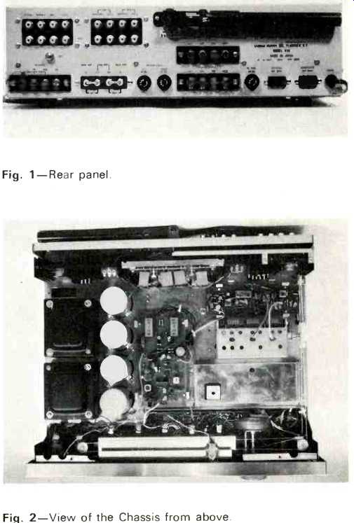
Fig. 1--Rear panel. Fig. 2--View of the Chassis from above.
Performance Measurements
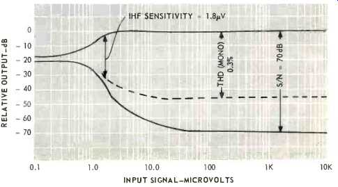
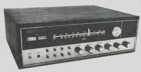
Fig. 3--Mono FM characteristics.
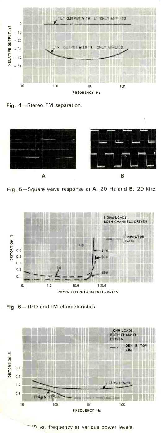
Fig. 4--Stereo FM separation.
Fig. 5--Square wave response at A, 20 Hz and B, 20 kHz.
Fig. 6--THD and IM characteristics.
Fig. 7-- THD vs. frequency at various power levels.
As shown in Fig. 3, IHF FM sensitivity measured exactly 1.8 µV as claimed. Ultimate S/N was 70 dB, and at 5 microvolts of input signal, quieting reached 57 dB. Impressed with the steepness of this quieting curve we checked to see where the muting threshold was set and found it to be at 10 microvolts. That's all right for a lesser performing set but we prefer to be able to have interstation silence and all the stations we can get with reasonable listenability. Happily, a small hole in the bottom cover is labeled "muting adjustment" and this enabled us to reset the muting at about 5 microvolts, where we felt it ought to be. Any customer can do the same, except that no mention is made of this feature in the otherwise complete instruction manual. THD in mono was a bit better than stated, measuring 0.3% while stereo THD for 100% modulation turned out to be 0.45%, considerably better than claimed. Figure 4 details the separation characteristics of the stereo FM circuits and in the case of our sample, it turned out to be one of those rare units that actually meets or exceeds transmitter separation requirements of the FCC--that is, we were able to obtain better than 30 dB of separation from 50 Hz right up to 15 kHz. At mid-band, separation was just over 40 dB, somewhat better than claimed. It takes a really superior piece of test equipment to verify this kind of separation performance and, fortunately, we now have just such a stereo generator.
To summarize, then, the tuner is as good as we expected it to be and should have no difficulty providing the kind of FM reception we all want to get, but it's the amplifier and preamplifier section that leaves this reviewer wide-eyed and somewhat awed. This is the kind of amplifier performance we tend to find (and then only rarely) in the very best separate preamplifiers and power amplifiers. For starters, consider the photos of Fig. 5 (however out of context it might be). Yes, they are reproduced square waves at--you'll never guess the frequencies 20Hz and-20,000Hz! Need we say more about the rise time and transient response of this amplifier? Incidentally, the photos were taken while feeding the signal through the entire system--preamp and amp sections--not the power amplifier section alone. The THD and IM characteristics of the 930 are plotted in Fig. 6. Note that at mid-band, rated THD was reached at a power output of 49 watts-more than the 45 watts claimed-and that, of course, was with both channels driven into 8 ohms loads.
Checking into the power claims made for the entire audio spectrum, we plotted THD versus frequency for rated and half power levels. At the very worst (20 Hz), THD measured twice as good as claimed at full power output--a mere 0.25%. At half power, THD readings were limited by our generator (which specs out at 0.05%) over most of the audio spectrum, reaching 0.1% at 20 Hz. Lower power levels are not plotted, since, in such cases, all readings would have been limited by our equipment. Power bandwidth extended from below 5 Hz (the limit, once again, of our audio generator) to 55 kHz, using the half power point and a 45 watt reference as our criteria as shown in Fig. 8. All hum and noise readings just about corresponded (within a dB or so) with published claims, both in low level and high level input settings. Tone control, filter, and loudness characteristics are plotted in Fig. 9 and are more or less typical of these types of circuits. Within the audio spectrum there was less than 0.5 dB of variation in frequency response with or without the tone control circuits defeated, but high frequency roll-off began a bit earlier (somewhere around 60 kHz) when the tone controls were actively in the circuit and set at their mechanical "flat" position.
Without the tone controls in the circuit, we "ran out of generator frequencies" at about 100 kHz and still were within 1 dB of our zero reference.
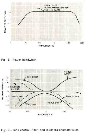
Fig. 8--Power bandwidth
Fig. 9--Tone control, filter, and loudness characteristics.
Listening Tests
We're the first to admit that it's very easy to become "brainwashed" by highly promoted engineering design features in this business and while "two independent power supplies" sounds like a sensible idea, intuitively, we wondered whether or not we would be able to hear any audible advantage in this arrangement. Frankly, at moderate listening levels we could not, but when we really began to pump power and used truly dynamic source material (such as the exciting two-disc Columbia album of the score from the film "Shaft") we knew, instantly, that there was something better about the sound we heard. In our listening experience, stereo separation often tends to become a bit "blurry" when we listen to stereo material at really ear-pounding levels. In the case of the 930 that just did not happen. Now, of course, this apparent improvement might be due to the excellent rise-time and square wave response, it might be due to the wide-band frequency response (which Harman-Kardon has espoused for years and years), or it might even be due to other design features which still elude us, but whatever the reason(s), this was our kind of sound-and our kind of sound, dear reader, is the kind that makes us feel like we are there-at the performance! P.S. Quite apart from any performance considerations, we came across a little pamphlet which H-K places conspicuously on top of their receivers, so that you can't miss seeing it and, hopefully, reading it, even before you unpack the set. The pamphlet is entitled, "The Outdoor Antenna, The Key To Better FM Reception," and it contains information about FM reception that is so valuable and so concisely and succinctly put that Harman-Kardon ought to make it available at a nominal cost to every FM listener or potential FM listener in the world!
--Leonard Feldman
(Audio magazine, June 1972)
Also see:
Harman Kardon Model 820 Stereo FM Receiver (Feb. 1970)
Harman-Kardon Model 900+ AM/FM Multichannel Receiver (Equip. Profile, May 1974)
Harman/Kardon Rabco ST-7 Turntable (Jan. 1977)
= = = =