TESTING AND EVALUATING audio equipment is one of the most interesting facets of preparing the editorial content of a magazine, and since the early 1950's has been an important function of practically every magazine in the field, both in this country and in hi-fi magazines throughout the civilized world. How it is done is usually unexplained and in any case is likely to invite criticism from readers and manufacturers alike-the latter particularly if the finished profile does not paint the product in as glowing terms as the advertising might have done. But in this writer's opinion, no test report is of value to the reader unless it tells the bad features of the product as well as the good ones. The advertising always tells the good points, but if there are any deficiencies in operation, they should be pointed out to the reader. In most instances, a product which does not come up to its specifications is not reviewed in print--the manufacturer is advised of the results of the tests, and if satisfactorily explained the profile is rechecked to determine the actual performance. If the recheck is still unsatisfactory, the profile does not appear in print. Fortunately, that happens only rarely, for most manufacturers offer equipment that has stood the tests of time or of continual upgrading by the factory to ensure that the product will be as good as possible in order to be a success on the market.
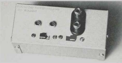
Fig. 1--Exterior view of battery-operated preamp used to provide sufficient
gain for use in turntable measurements. Since this photo was taken, another
switch has been added to place a 10-µF capacitor in the feedback circuit
to give flat response.
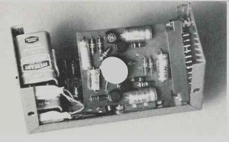
Fig. 2--Inside view of the preamp. Entire circuit is on etched board which
plugs into circuit-board socket shown at right.
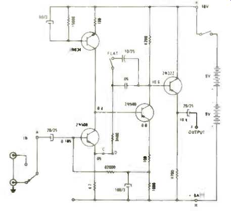
Fig. 3--Circuit of the battery-powered preamp used to boost output from
magnetic to level adequate for measurements.
The Test Procedure
The first step in testing is the unpacking. This seems simple, but when it must be considered that the product is to be returned to the manufacturer is the same condition it was received, the unpacking operation becomes important. Placement of packing material, wrapping in the usual plastic bag, protection of the external leads, placement of accessory equipment-all are important when the equipment is to be repacked. Our custom is to replace all the corrugated cardboard material, plastic wrappers, rubber bands, and any other surplus items back in the original shipping box. Some manufacturers provide diagrams on the outside box or on an enclosure which show just exactly how the unit should be repacked, and to these manufacturers go our unqualified thanks. It is often a month after unpacking before the unit is to be returned to its box and thence to the manufacturer, so the routine of unpacking is likely to have been forgotten. That is why we applaud the diagrams which make the job easier.
The equipment is then given a visual inspection to determine its various features, as well as to aid in restoring it to its normal condition before the actual testing begins. Then it is photographed as a whole, and in as many separate shots as seem to be desirable to point out the specific characteristics of the product. For a turntable, this implies shots of the controls, the platter--often from top and bottom-the arm and its features, the top of the unit with the platter removed, and the underside of the chassis. This usually results in from six to ten separate "poses," with four to six usually ending up in the profile as it appears in the magazine.
The unit is then reassembled, and if a cartridge is not supplied with and mounted in the head or on the cartridge slide, we pick out a reliable make of cartridge and install it. Since we are not measuring cartridge characteristics in a turntable test (in most instances) it makes little difference what cartridge we use, assuming it is not especially susceptible to hum pickup. The unit is then turned on and left running with no record on the platter for an hour.
Before making any measurements, the next step is to study the instruction book to find out if there are any unusual features that should be described in the write-up, and--contrary to the time-honored custom of audiophiles everywhere--to find out how the unit should be operated. Surprising how often this prevents our damaging the machine by doing something wrong, and often it simplifies the actual operation.
The first measurement that we normally perform is that of wow and flutter. To get sufficient level for such a measurement, the output of the cartridge must be amplified, so it is plugged into a small battery-operated preamp which has been in use for a long time and not yet brought up to date with a modern IC form of construction. The device derives from an early GE transistor manual and uses four PNP transistors--two 2N508's and one each of 2N634 and 2N322. Since the photos were taken, an additional switch has been added to connect a 10µF capacitor across the 0.05µF unit in the feedback network to give a gain of 46 dB and a flat response, whereas the original supplied bass boost and no high-frequency rolloff. A SPDT switch selects either left or right cartridge coil, and the output is fed to further measuring equipment. The gain is 46 dB, and the output noise is 0.5 mV with the input terminated, 1.0 mV with the input open circuited.
Using a CBS BTR-150 test record, we next play the 3000-Hz band, feeding the output of the battery-operated preamp to the input of a wow-and-flutter meter-the one described in these pages in the spring of 1966. The writer has used this unit consistently for the intervening years, and while it does not provide "weighted peak flutter" in accordance with the new IEEE Standard 193-1971, it does indicate the difference between wow, or low-frequency speed variation, and flutter, which is high frequency variation. The wow and flutter are measured separately with this instrument, and the figures recorded.
Plans are under way for the addition of a 4-Hz filter to permit weighted peak flutter as specified. In the meantime, a Ferrograph RTS-1 is also used. See page 61 for a review of this unit.
The next step is to determine the range of vernier speed variation provided by the control. The output of the preamp is fed to a Heathkit IB-101 frequency counter, and the 1000-Hz band of the record is played, with the control at the normal position. The indicated frequency is noted, as are the frequencies at both extremes of the vernier control. This is easier and quicker than counting revolutions, and percentages of speed variation can be calculated from the frequencies read.
Still using the frequency counter, the line voltage is varied from 120 to 135 and down to 85, with variations in indicated frequency being noted and recorded. Then with the voltage held at 120, a varying frequency ranging from 40 to 90 Hz is applied to the turntable and speed changes again noted and recorded. With synchronous motors, the speed varies with frequency, and only slightly (if at all) with variations in voltage. Induction motors maintain the same speed regardless of frequency (within the range noted above), and their speed increases with higher voltages just a little, and drops off quite rapidly down to the lowest voltage applied. All of these figures are recorded.
The next to last measurement we make is the important one of signal-to-noise ratio. There are many different ways in which this measurement can be made, particularly as to the reference.
The NAB Standard further specifies level of 1 cm/sec peak velocity at 100 Hz, with the further notation that this level corresponds to a peak velocity of 5 cm/sec at 500 Hz. A peak velocity of 5 cm/sec results from an rms velocity of 3.54 cm/sec, and since most standard records rely on a frequency of 1000 Hz for their reference, a correction factor of 3.0 dB must be added to the numerical value of measured S/N to obtain a valid figure. Thus our actual reference is 3.54 cm/sec rms velocity at 1000 Hz, and the correction factor is added.
The NAB Standard further specifies that the response of the measuring system shall fall off at the rate of 12 dB/octave above 500 Hz, and with this proviso, the acceptable turntable shall have a S/N of 50 dB if the response of the measuring circuit is flat from 1000 Hz to 15,000 Hz, and rolls off at the rate of not less than 12 dB/octave below 500 Hz. This therefore eliminates the effect of hum and/or rumble, and constitutes the high-frequency S/N. We customarily measure with an RIAA low end (500-Hz turnover) and a flat high end. The presumed ARLL (audible rumble loudness level) figure derives from the "flat" measurement which corresponds roughly to the rolloff of human hearing at low frequencies at low levels.
Thus we again use the battery-operated preamp and feed its output to an a.f. voltmeter, making sure that grounding results in the lowest possible hum.
We then play the 3.54-cm/sec, 1000-Hz groove of the STR-150 record and note the level. Next we play the "silent" groove and again note the levels in both positions of the preamp-bass boosted and flat. The difference between the 1000-Hz level and the level of the silent groove in the boosted position represents the measured value of the S/N, to which must be added the correction factor of 3 dB. The figure obtained with the preamp "flat" closely approximates the ARLL value.
The average measured S/N is in the vicinity of 38 to 40 dB, resulting in a figure of 41 to 44 dB when the correction factor is added. The ARLL figure is usually about 19 dB better than the value obtained with the preamp in the bass boost position.
These constitute the major measurements made on turntables. In the case of automatic models, the change time is noted, both for start and for the time from the tripping of the mechanism at the end of one record to the setdown of the arm on the next record.
There are several other measurements that could be made, but none is considered necessary with modern turntables. Among these additional measurements are the horizontal and vertical forces to move the arm. The requirements for these measurements are quite precise and are complicated to perform, but on any hi-fi turntable they are hardly considered important. The measurement of "stiction" which is the term given to the force required to start the arm moving is even more complicated, and still not considered important.
Arm resonance is measured by playing the 200-to-10-Hz band of the CBS STR-100 record and recording the output on a graphic recorder. If the arm resonance falls within this range, a small flick will be seen on the recorded curve, and by interpolation this frequency of resonance can be determined.
If it does not fall within this range, it is simply reported as being "below 10 Hz." Finally, the unit is connected to an amplifier and a number of records played-automatically if it is a changer, and manually if not. Overall handling is noted, as well as any eccentricities the unit may have. Stylus force is decreased until faulty reproduction is heard as well as noted on a scope.
Visual observation of the general performance of the turntable completes the test procedure. Then, and only then, can a valid Profile be prepared, and since this procedure does not constitute part of the testing, it will not be described other than to say that the Profile results from a compilation of the information gained from the testing, and written in as readable a form as this observer can produce.
-C. G. McProud
(Audio magazine, Jun. 1972)
Also see:
The Skating -Force Phenomenon--Part 1 and 2 (Oct./Nov. 1967)
A Quiet Phonograph Preamplifier (Oct. 1972)
How we test a Phono Cartridge (Aug. 1972)
A New Concept in Diamond Syli (Aug. 1972)
Ultra Low-Noise Phono Preamp [theory, concept, design and DIY project]