by Maxwell G. Strange
THE SERIOUS collector of older recordings faces the challenge of getting the best possible sound from imperfect originals. Most of these records are quite noisy by today's standards. For example, 78 rpm commercial discs, even though in mint condition, will have a typical signal-to-noise ratio of only 30 to 35 dB due to the somewhat abrasive nature of the record material.
Most collectors dub their best records onto tape. This way they may be played as often as desired--and conveniently shared with other collectors--while the often irreplaceable originals are safely preserved. Also, the sound can often be improved considerably during the copying process through equalization and filtering. I'm going to describe a flexible, low-cost noise filter designed for taping records with a maximum "fidelity-to-noise" ratio. It can be duplicated by the serious electronics hobbyist for about $60, or slightly less if certain features or ranges won't be needed. Although not recommended as a beginner's project, the experimenter with some circuit experience should have no difficulty.
Minimum equipment requirements are an oscilloscope, sine wave generator, and multimeter.
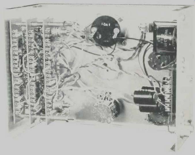
Fig. 1--Interior of the dynamic filter.
The heart of this circuit is a dynamic noise suppressor with frequency characteristics and convenience features which are optimized for its intended use. The concept of dynamic noise suppression has existed for many years. Workable circuits were designed by H.H. Scott in 1946, and their performance was improved by Scott and others in 1947 and 1948.
Then, with the advent of the vinyl microgroove record and the rapidly increasing use of tape, both of which offered a considerable noise improvement over the 78 rpm system, the dynamic noise suppressor was almost forgotten. Recently, R. Burwen has revived this principle and applied it primarily to tape playback. Taking full advantage of modern integrated circuits, Burwen has designed highly sophisticated and flexible systems with impressive specifications. These, however, are too expensive for many hobbyists and do not have frequency characteristics optimized specifically for old, intrinsically band-limited material.
Theory
Dynamic noise suppression is simple in concept. Record surface noise varies in spectral content, but the higher frequencies (above 1 or 2 kHz) predominate. Low-pass filtering is commonly used to limit noise. But unless used sparingly, this type of filtering band-limits the program material, making it sound muffled and lifeless. The dynamic filter, however, provides a method by which a signal can be effectively extracted from the noise (at least subjectively) when signal and noise occupy overlapping frequency ranges.
Operation of the dynamic noise suppressor depends upon a characteristic of the human auditory apparatus. If two signals occupying well-separated frequency ranges are present simultaneously, they are clearly perceived as individual entities. (This effect is often used to advantage in public address systems for noisy environments. If considerable high-frequency boost is used, voice announcements will seem to cut through ambient noise of predominately lower frequency without having to be excessively loud.) This is the case, at least for a large portion of the time, for a typical recorded signal with attendant surface noise; hence, the annoyance of the noise. However, if two simultaneous signals occupy substantially the same frequency ranges, the ear will tend to hear only the louder signal and ignore the weaker one. A level difference of only a few dB is sufficient for one signal to effectively override, or mask, the other.
Operation of the dynamic noise suppressor depends upon this masking effect.
The dynamic filter has a fairly steep low-pass characteristic which, in the absence of signal, starts cutting off at about 1 kHz. This very effectively rejects the noise spectrum. When a signal having high-frequency components at sufficient amplitude comes along, the filter is made to "open up"; that is, its cutoff frequency is quickly raised. As the high-frequency program content drops in frequency and/or amplitude, bandwidth contracts. The idea is that when high-frequency signal components are present, they will tend to mask the accompanying noise. When highs are not present, the wide bandwidth is not needed. Admittedly, the recovered signal is not as faithful as a noise-free original would be. For example, high-frequency content in low-level passages may be lost. Of some help here is the fact that many musical instruments tend to have less harmonic content at low acoustic levels. In spite of this compromise, the processed signal is usually far more pleasing to the ear than the noisy input signal.
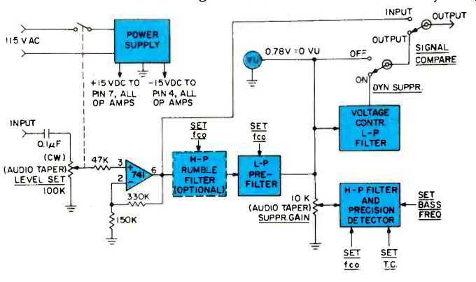
Fig. 2--Block diagram of system.
The bandwidth control signal is derived by separating the high-frequency program components from the signal-plus noise. Unless the signal level is consistently higher than the noise to begin with, this becomes impossible. Thus, there is a minimum signal-to-noise requirement below which no improvement is possible. As the original S/N improves, the dynamic suppressor's performance improves also.
Ideally, the signal frequency range to which bandwidth is most sensitive should correspond to the frequency range of maximum noise. The optimum filter characteristic for separating the bandwidth-control signal from the noisy input thus varies widely with the characteristics of the noise with which we are dealing. Bandwidth control sensitivity (or gain) must be set properly for the incoming signal level and noise properties. Bandwidth should respond rapidly to signal changes to avoid loss of transients and to prevent audible "swishing" sounds which can be produced by delayed bandwidth contraction.
Design Approach
I have tried to implement the basic requirements outlined above as completely as possible in an easy-to-use, low-cost unit. A dynamic high-pass filter stage was considered but later dropped, as high-frequency noise predominates on most older records. It is my experience that low-frequency noise can usually be handled adequately with a simple manually-set rumble filter.
Figure 2 shows an overall block diagram of the noise filter. Operational amplifier A1 is connected as a non-inverting amplifier with a voltage gain of 3.2 (10 dB), enabling the system to be driven to 0 VU with an input level of 0.25 volt. This amplifier also serves as a buffer, providing an input impedance of 100 kilohms for compatibility with virtually any signal source.
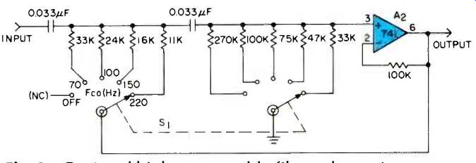
Fig. 3--Optional high-pass rumble filter schematic.
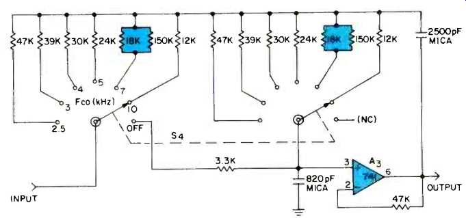
Fig. 4--Schematic of the low-pass pre-filter.
Amplifier A1 drives the rumble filter, which could be omitted if one is available in the associated external equipment. Following this is the pre-filter, which is simply a low-pass filter with a manually-set cutoff. This filter is important for several reasons. First, it removes noise which is above the frequency range of the recorded signal. Many recordings have no signal content above 4 or 5 kHz (even lower for acoustic records), and no program content is lost by cutting off the upper range. Thus, the total noise voltage is lowered, often appreciably, permitting the use of higher suppression gain settings as will be seen later. Another reason for this filter is that the dynamic filter can do nothing to reduce the annoyance of high-frequency distortion. Furthermore, since a limited-bandwidth signal cannot effectively mask higher frequency noise, removal of the latter helps to eliminate audible evidence of the continually changing bandwidth.
From the pre-filter output the signal passes to the voltage-controlled l-p filter and, via the suppression gain control, to the h-p filter/precision detector whose function is to derive the bandwidth control signal. This point additionally goes to a switch which permits the dynamic filter to be bypassed at will so that its effect with various control settings may be easily judged. Another switch permits the output to be compared with the "raw" input signal.
All of the filters used in this system, including the voltage-controlled filter, are of the 2-pole active type, giving a 12 dB/octave rolloff slope. The damping factor is chosen (with one exception) for a Butterworth response, which produces the steepest possible slope beyond cutoff with no peaking in the passband. (High-pass filters with 3-dB peaking were tried, but these produced a slightly rough, "grainy" sound compared to the flat-passband version.) The design approaches are widely published and need no further discussion here. The rumble filter (Fig. 3) and the pre-filter (Fig. 4) are of this type; their response curves are shown in Fig. 5. The rumble filter is not essential to proper suppressor operation, but is convenient in case an effective low-cut filter is not included with the associated preamplifier in the copying setup. The design shown here has rather high settings intended primarily for acoustic records.
The bandwidth control signal is derived with the circuit of Fig. 6, which consists of a high-pass filter followed by a precision detector. The filter damping factor is made low in order to produce a pronounced peak and more rapid low frequency rolloff (Fig. 7). Three selectable cutoffs produce peaks at 3.5, 5, and 7.5 kHz; these were empirically determined to best accommodate a wide range of noise characteristics and recorded bandwidths. The filter output is coupled to the detector via a small capacitor to make the low-frequency rolloff even steeper below 1.6 kHz. The precision full-wave detector uses diodes in the feedback circuit of an op-amp to effectively produce ideal rectification characteristics down to the millivolt region. The output amplifier doubles as a post-detection filter. Resistor R determines the gain, and capacitor C makes this stage behave as an operational integrator with time constant RC. A switch is provided for increasing the time constant by paralleling capacitor C1; this is helpful with sources having sharp impulse noise. The output of the detector/filter circuit controls the bandwidth of the dynamic suppression filter according to the curve of Fig. 9.
Early experiments showed that it is undesirable to make the no-signal cutoff lower than absolutely necessary to substantially reduce noise with a particular signal source. When the cutoff is made lower than actually needed, weak signals are unnecessarily band-limited and the dynamic filter produces such a level-dependent bandwidth contrast that its action is much more likely to be audible. Hence a BASE CUTOFF (not "BASS CUTOFF") control was found to be desirable. This control is simply a pot which offsets the detector output at zero signal level by applying a variable reference voltage to the op amp non-inverting inputs. This voltage, variable from about-1 volt to-6 volts, establishes a "starting point" or base cutoff frequency which can be set just low enough to virtually eliminate no-signal noise.
The variable-cutoff filter, Fig. 8, is the very heart of the system. Since there is some part selection and adjustment necessary, it must be checked out separately. The basic configuration is similar to that of the pre-filter, except the tatter's switch-selected resistors have been replaced by field-effect transistors (FETs). FET channel resistance R Ds changes as a function of gate voltage V_cs as shown in Fig. 11, thus varying cutoff frequency. A resistor across each FET establishes a solid lower cutoff limit and smooths the control characteristic as the FETs approach their "off" state. The gate circuit network, consisting of diode D1 and resistors R1 through R5, is used to empirically shape the control curve (Fig. 9) for best audible results. Diode D1 prevents excessive positive gate drive, maintaining isolation between the gate and signal circuits.
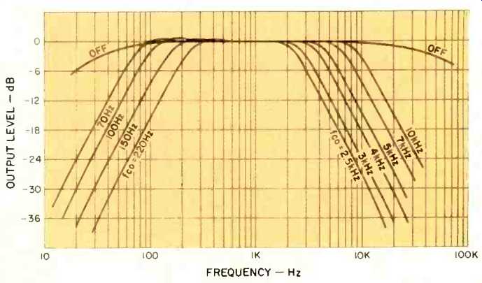
Fig. 5--Frequency characteristics of the manually-set rumble filter and pre-filter.
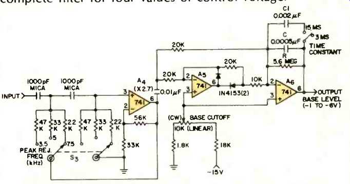
Fig. 6--Bandwidth-control signal separation filter and precision rectifier.
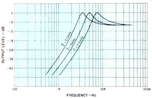
Fig. 7--Frequency characteristics of the filter used to derive the bandwidth
control signal.
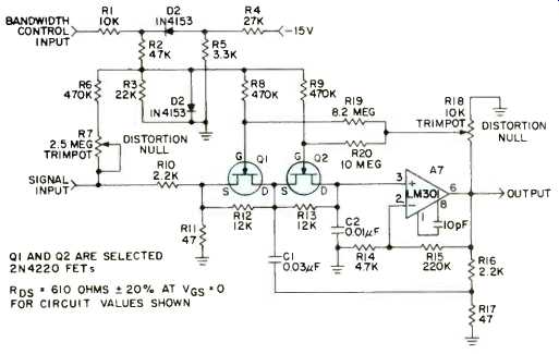
Fig. 8--Voltage-controlled filter schematic. FETs Q1 and Q2 are critical and
must be selected (see text).
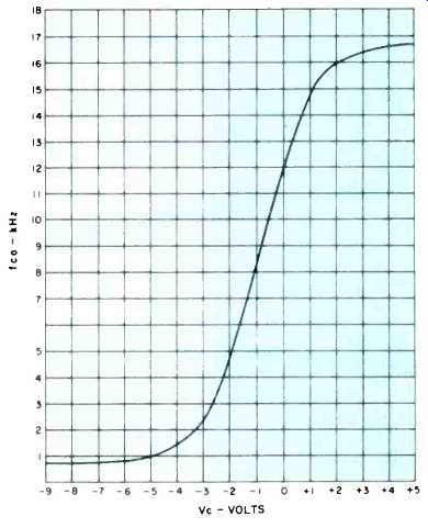
Fig. 9--Variable-bandwidth filter cutoff frequency vs. control voltage.
An input attenuator (R10 and R11) limits the signal amplitude presented to the FETs to about 0.1 volt p-p at 0 VU to ensure low distortion. Output amplifier A7 makes up exactly for this loss. An op amp having external frequency compensation was used here so that this relatively high-gain stage could be tailored for flat response to 15 kHz (a µa741 could be used, but would roll off slightly above 10 kHz). Resistors R16 and R17 attenuate the output signal by an amount equal to the gain, so that this amplifier doubles as the unity-gain buffer required for filter operation. The highest cutoff frequency is dictated by minimum FET resistance and capacitors C1 and C2. The latter should have values in a ratio of about 3:1 to produce the desired Butterworth response. Figure 10 shows the measured response of the complete filter for four values of control voltage.
Unfortunately, FETs vary widely in characteristics, even between units of the same type, so these devices must be selected. The two FETs must be reasonably well matched over a 15:1 Ros range for a 15:1 range in cutoff frequency (15 kHz to 1 kHz). (Dual matched FETs are available, but are more expensive and not necessarily matched for the parameter of interest here.) A transistor curve tracer is most convenient for this purpose and permits selection for best linearity as well as matching. I used N-channel 2N4220s on hand ($1.50 each) and selected the best matched pair out of a group of 6 units. Figure 11 shows the V-I characteristics of one of these. There are many other inexpensive FETs which should work as well, such as the 2N5484, 2N5716, and 2N5717 at under $1 each. In fact, any general-purpose, depletion type FET with fairly low zero-bias current ( loss) and pinch off voltage (Vp) should be usable. P-channel units would require reversing diodes D1 and D2 and the polarity of the control voltage.
If a curve tracer is not available, the setup of Fig. 12 can be used. A transistor socket will facilitate changing FETs. A good procedure is to first measure Ros at Vcs = 0. Then increase Vcs (negatively for N-channel FETs) until Ros is about three times the zero-bias value; this corresponds to a mid-range cutoff frequency where matching is the most critical. With this Vcs setting try different FETs until a 10 percent or better match is found. If Ros values seem to cluster higher or lower, try another unit as a reference and try matching to it. When matched units are found, check the match at minimum Ros (Vcs = +0.5 V) and at 10 times this value of ROS . A 20 percent mismatch can be tolerated at these extremes. My 2N4220s measure 610 ohms at zero bias, 360 ohms at Vcs = +0.5 V., and about 8 kilohms at Vcs = -0.7 V. R11 and R12 are chosen for a cutoff of between 800 Hz and 1 kHz with the control voltage at its maximum negative value of about-6 volts. Circuit cutoff at zero FET bias should be roughly 12 kHz (see Fig. 9). A slight forward bias, limited to about +0.5 volt at the FET gates by diode D2, then boosts the cutoff to at least 15 kHz with maximum positive output from the precision detector.
Resistors R6, R7, R18, R19, and R20 reduce harmonic distortion significantly. R6 and R7 feed some signal to the FET gate circuit so that signal voltage does not appear between source and gate, which would make Ros vary slightly with instantaneous low-frequency signal amplitude and polarity.
R18, R19, and R20 feed back some output signal to the gates to further reduce distortion (this is a cancellation effect, not true negative feedback). Distortion settings are best made in the vicinity of cutoff, where FET linearity is the most critical. Connect a variable voltage d.c. source (the slider of a 5K pot temporarily connected between-15 V and ground will suffice) to the bandwidth control input and set it for a cutoff frequency of 2 kHz. Then, with a 2 kHz sinusoidal input at about 0 VU (2.2 V p-p), set trimpots R7 and R18 for lowest harmonic distortion at the output. It should be possible to sharply null the total harmonic content, which consists primarily of the 2nd and 3rd harmonics, to at least 60 dB below 0 VU. Then vary the cutoff frequency and make sure distortion is low for all settings. Of course, the filter itself will reduce harmonic distortion appreciably at its lower cutoff values. Lacking a distortion meter or wave analyzer, these adjustments can be made quite well by driving the input at 7 volts p-p (10 dB above 0 VU) to accentuate the distortion and setting very carefully for a symmetrical output waveform as monitored by a 'scope. Fixed resistors, determined by two decade boxes (the settings interact somewhat), could replace the pots. These adjustments, once made, are permanent unless the FETs are changed.
Fig. 13 shows the distortion of the complete noise filter measured at two fixed values of bandwidth control voltage.
At normal levels, distortion is so low that it is largely a measurement of the harmonic distortion of the test oscillator. The large margin above 0 VU passes the highest program peaks ever likely to be encountered without clipping.
The simple power supply of Fig. 14 easily supplies the power requirement of ±15 volts at about 10 mA.
Construction
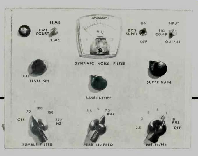
The entire filter can be duplicated for about $60 with new parts. Sources of the major components are shown in the Parts List; substitutes can be used in most cases. Quarter watt, 5 percent composition resistors are suitable. Layout is not critical, since signal levels are high and impedances are relatively low. I strongly recommend that each of the functional blocks of Fig. 2 be built and checked for reasonable conformance with the curves before integration into the system. This makes troubleshooting for errors and occasional bad components much easier, practically ensuring success. My unit (Fig. 1 and lead photo) is a "breadboard in a box." The circuit is still undergoing occasional changes, even though it is a third-generation model. Parts are mounted on terminal boards which were on hand. A neater approach would be to use the commercially-available perfboard with snap-in terminals.
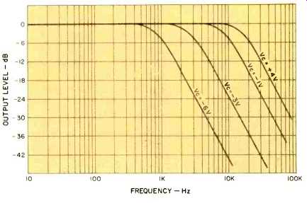
Fig. 10--Variable-bandwidth filter characteristics for several control voltage
values.
Operation
After checking the wiring, apply power to the unit and check for proper power supply voltages. Positive and negative supplies should both be between 14 and 16 volts with respect to ground. Much lower values would indicate a short circuit or bad op amp. Current drain should be on the order of 10 mA.
The noise filter can be conveniently connected to your audio system by means of the Tape In and Tape Out jacks included on most preamplifiers. An advantage to this connection is that the processed signal passes through the pre amp tone controls, which can be set for the most pleasing final balance. For taping, the recorder input is paralleled with the output which drives the power amplifier.
For initial set-up experience, a record having a good frequency range and moderate, steady surface hiss is desirable. (A slightly noisy FM station can also be used, but results will not be quite as good because of the latter's flatter noise spectrum.) Initial control settings should be:
- Pre-Filter: Off
- Rumble Filter: Off
- Time Const: Off
- Peak Rej. Freq.: 5 kHz
- Base Cutoff: CCW
- Suppr. Gain: CCW
- Dyn. Super.: Off
- Sig. Compare: Input
The signal should now pass through the unit unaffected, except the Level Set control will vary the gain from zero to 3.2 (10 dB). Set the level for 0 VU on signal peaks as you would set a recording level. Whenever the source is changed, the signal level should be reset as necessary.
Now switch the Sig. Compare switch to "output." The signal is now passing through the rumble filter (if used) and pre-filter, but bypassing the dynamic filter. Lowering the Pre-Filter cutoff setting should progressively cut off the highs. At the lower settings, which are primarily for acoustic records, the signal will sound severely band-limited. The best setting is the lowest cutoff which does not significantly affect the recorded bandwidth. I have found that with vocal music, the unfiltered sibilant sounds provide a means of judging bandwidth. If sibilants are quite strong and natural, a 7 kHz or higher cutoff is indicated. If they are weak or have a slight "whistling" sound, the upper limit is about 5 kHz. If sibilants are lacking, a 4 kHz or lower setting is best. Of course, the presence of high-frequency distortion may dictate a compromise setting a notch or two lower than indicated above. The filtered and unfiltered sounds may be compared at any time by means of the Sig. Compare switch.
The optional rumble filter is used for the occasional records which have warpage or bumps or low-frequency noise in the recording. For acoustic records it can be routinely left at 150 Hz, as nothing is recorded below about 200 Hz.
Next flip the Dyn Suppr switch to "on," putting the dynamic suppressor in the circuit. The sound should become very dull and lifeless, as the high-frequency cutoff is now 1 kHz or less. Increase the Base Cutoff setting until record noise just begins to be audible. The signal will probably still be quite lacking in high-frequency content (if it is not, only the pre-filter may be needed for this particular source). Now turn up the Suppr Gain slowly. This should "magically" restore the highs without increasing the noise level. The highest possible setting which does not noticeably increase the noise is normally best.
At this point it is edifying to monitor the bandwidth control input signal to the variable-bandwidth filter with a d.c. coupled oscilloscope. The instantaneous voltage here is a measure of high-frequency program amplitude and dynamic filter bandwidth (see Fig. 9). It should follow transients rapidly and may reach saturation (about +14 volts) on musical passages having high harmonic content and on strong voice sibilants.
The Peak Rej. Freq switch selects the frequency of peak rejection by choosing the appropriate filter curve (Fig. 7) for separating the bandwidth-control voltage from the input signal. The 5 kHz position is used for most electrical 78 rpm records. For acoustic records or very noisy electrical 78s where the pre-filter is set for 4 kHz or less, the 3.5 kHz position gives better results. Here the Time Const. switch can be set for 15 mS. The longer time constant also helps to attenuate sharp clicks and pops occurring in quiet passages, as it prevents the bandwidth from increasing rapidly enough to follow their steep wavefronts. The 7.5 kHz position is used for wideband recordings and tape.
With a little practice, you will be able to set the controls quickly for optimum performance. It is often best to set the Base Cutoff for a significant improvement, rather than to try to eliminate the noise completely. This will minimize low-level band limiting, and the suppressor will be less likely to betray its presence with obvious bandwidth changes.
Performance
Figures 5 and 10 indicate the bandwidth ranges available.
The pre-filter and dynamic filter (slope is 24 dB/octave above both cutoffs) can together provide well over 60 dB of noise attenuation at 10 kHz and over 40 dB at 5 kHz. The overall improvement in signal-to-noise ratio is strongly determined by the character and spectrum of the noise, which varies greatly with records. With the steady hiss typical of new electrical recordings on shellac, an average improvement of 8 dB (unweighted) is realized from the dynamic filter alone. Including the effects of the rumble filter and pre-filter on band-limited material, S/N improvement can be more than 12 dB. The apparent improvement is even greater, since the ear heavily weighs the higher frequencies where record noise is concentrated. The effect of the noise filter is surprisingly great on records which were originally thought to be quiet without filtering. It is a little weird at first to hear a familiar old record with realistic strings and brass and clear voice sibilants, but with the background suddenly rendered deadly quiet. I have spent many hours listening to the records and tapes in my collection and enjoying them anew.
The noise filter works very well on tape noise, providing at least 8 dB total S/N improvement. A stereo version built for tape only could be simplified considerably, as only the Level Set, Base Cutoff, Suppr. Gain, and Sig. Compare controls would be needed. The power supply as shown can easily handle two channels.
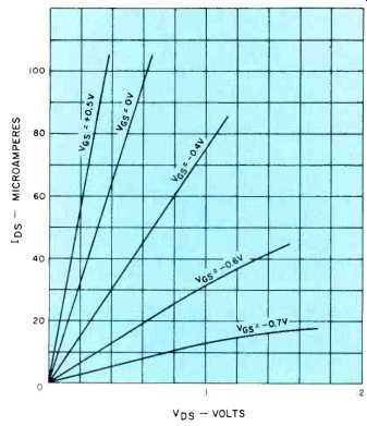
Fig. 11--Variable-resistance characteristics of a junction field-effect transistor
with low values of drain-to-source voltage.
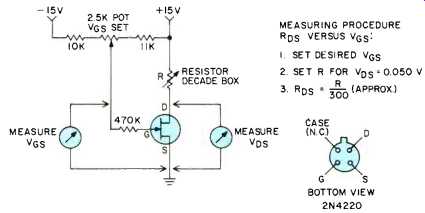
Fig. 12--Set-up for selecting FETs by static measurements (see text). Small
15V batteries or the power supply of Fig. 13 may be used.
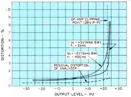
Fig. 13--Overall harmonic distortion of the noise filter for two constant
values of bandwidth-control voltage.
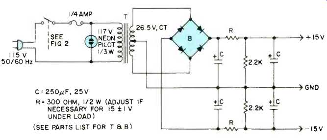
Fig. 14--Power supply. A two-channel suppressor may easily be powered by reducing R slightly.
The noise level of the filter itself depends mostly on output amplifier A7. Of several units I tried, the noise level ranged from 62 to 68 dB below 0 VU. A few tips on the mechanical aspects of copying records are in order here. The importance of good tracking cannot be overemphasized. More can be gained here than with any amount of electronic processing. Groove radius, depth, and angle were not standardized on early discs, and experimentation with tracking force and stylus size, if possible, may yield a considerable improvement in both noise and distortion. The playback stylus should, of course, ride on the sides of the groove. If it is too small it may ride the bottom of the groove and skate from side to side in a partially uncontrolled manner, creating severe distortion. If too large, it will ride high in the groove where it is more sensitive to surface blemishes. Also, larger styli cannot follow high-frequency modulation as well, especially on the inner record grooves.
Elliptical styli are helpful on relatively wide-range 78s if the latter have not been damaged by previous playings.
Acoustic records (1925 and earlier) tend to have a larger groove, since with acoustic playback the mechanically-imparted stylus motion had to supply all the sound power. For these, a stylus of 4-mil (.004") radius may produce better results than the standard 3-mil size. Custom-made styli with a "truncated" tip (really a smooth transition from a 2or 3-mil radius to about a 4-mil radius at the very tip) have been used to track the groove sides of 78s properly while avoiding contact with the bottom. (Truncated and other special styli are available from International Observatory Instruments, 5401 Wakefield Drive, Nashville, Tenn. 37220.) Although not a cure-all, these can give dramatic results on selected discs. A 2.5-mil stylus is best for most post-1946 transcriptions.
Obviously, the pickup should have adequate lateral compliance and should produce no output for vertical motion.
Incidentally, electrical recordings made before the mid 1940s are mostly recorded flat, that is, they have no high-frequency pre-emphasis, while later records have pre-emphasis of as much as 16 dB at 10 kHz.
Edison cylinders (160 rpm) and discs (80 rpm), some Pathé discs, and some early wax transcriptions are vertically modulated. Here the stylus does ride on the groove bottom, and the pickup should have only vertical response. This can be obtained (as can lateral-only response) from a suitably phased stereo cartridge. Stylus radii of 4 to 10 mils are typical here; as always, experimentation is in order.
Future Development
The experimenter may want to try to improve the performance of the circuit described. Of course, additional types of processing can be added, such as more effective click suppression at the filter input or multi-channel equalization at the output. These would be electrically independent of the noise filter, and beyond the scope of this paper. However, there are some possibilities for improving the noise filter itself. Many of these, unfortunately, would require an incongruous increase in complexity and cost.
Sharper filter cutoffs give a marginal improvement on very noisy material, but setup adjustments become more critical. Dynamic high-pass (low-cut) filtering using a simple 6 dB/octave slope might be a reasonable addition. Since the noise-rejection frequency band of the low-pass dynamic filter should complement the noise spectrum of the signal, a statistical study of record and tape noise spectra might lead to a better shape for the bandwidth-control-signal separation filter of Fig. 7. The separation filter selector could be ganged with the pre-filter cutoff switch to eliminate one control knob. Perhaps a noticeable improvement could be realized by experimenting with the shape of the bandwidth control characteristic, Fig. 9. The attack time constant could be shortened by using a more elaborate filter at the precision detector output; this would improve the response to occasionally encountered wide-band transients.
An obviously desirable change would be to replace the FET bandwidth-control filter with one of the voltage-controlled state-variable type. This would eliminate the need for FET selection, but would increase the cost several-fold. It therefore appears that the original goal of high performance per dollar has been achieved, yielding a practical design which is within reach of the hobbyist.
References
1. Burwen, R.S., "A Dynamic Noise Filter," J. Audio Eng. Soc. 19, PP. 115-120, Feb., 1971.
2. Mori, T., "Designing Low-Frequency Active Filters," Electro-Technology, P. 72, Jan. 1968.
3. Langford-Smith, F., Ed., "Reproduction From Records," Radiotron Designer's Handbook (Wireless Press, 1953), PP. 701-774.
4. Scott, H.H., "Dynamic Noise Suppressor," Electronics, PP. 96-101, Dec., 1947.
5. Fletcher, H., "Loudness, Masking, and Their Relation to the Hearing Process and the Problem of Noise Measurement," J. Acoust. Soc. Am. 9, PP. 275-293, Apr., 1938.
Parts List:
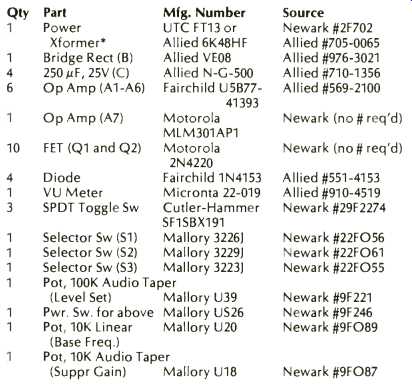
*Allied transformer is larger than UTC, but costs less.
These parts should be available at any industrial electronics supply store. Some electronics parts distributors will also carry. For mail order use Newark Electronics, 500 N. Pulaski Rd., Chicago, III. 60624 or Allied Electronics, 401 E. 8th St., Fort Worth, Texas, 76102.
(Audio magazine, June 1975)
Also see:
Men of Hi-Fi--Adrian Horne of Dolby Laboratories London (Feb. 1973)
A New Standard in Turntable Speed Constancy (June 1978)
= = = =