Authors: * Roger Anderson, L.R. Happ, B.W. Jakobs, F.J. Karlov, James H. Kogen,
and S.A. Mastricola.
[* Anderson, Assistant Chief Engineer; Happ, Project Engineer; Jakobs, Director of Development and Application Engineering; Karlov, Manager of Electromechanical Development; Kogen, Vice President of Development and Design Engineering, and Mastricola, Senior Development Engineer, Shure Brothers, Inc., Evanston, Ill.]
In the first part of this article, we discussed several important factors which must be considered in the phonograph playback process. We divided those factors into two categories, namely, those which relate to reproducing the modulation of the groove under ideal conditions, and, secondly, those which create practical problems in playback.
Specifications which describe the performance of a cartridge under ideal conditions include frequency response, separation, trackability, and distortion. Principal practical problems are extremely high modulation levels, record warp, structure-borne noise, cartridge-tonearm resonance, static electricity, and the accumulation of contaminants on the record and stylus. It was shown that all of these practical problems can have serious and decidedly negative effects on sound quality.
The objective in designing a phonograph cartridge should be twofold.
First and foremost, we must maximize the ability to play under ideal conditions. This requires that the cartridge have a flat frequency response that extends over the entire audible range.
Trackability must be sufficient to handle all the program material found on records. Distortion should be below detectable levels, and crosstalk should not impair stereo balance. In addition to those performance factors, output level must be high enough to prevent signal-to-noise problems. Hum and r.f. pickup must be within acceptable limits. Finally, and of critical importance, the cartridge should play at tracking forces low enough to prevent rapid wear of both the stylus tip and the record surface. From our experience, tracking force should be below 1 1/2 grams.
Since ideal conditions almost never exist, the second objective must be to reduce or eliminate the effects of non ideal playing conditions. One obvious method is to provide a variety of accessory devices which may be used in conjunction with, or as appendages to, the cartridge-tonearm system. Many such devices are available that are meant to reduce the effects of mechanical noise, cartridge-tonearm resonance, static electricity, and record contamination. Such "add-ons" are almost never ideal design solutions since they lack the optimization derived from a total system design approach. The better solution is to provide a phonograph cartridge system that can operate without deterioration of its performance in the presence of non-ideal conditions. To design such a cartridge means a major expansion of objectives as compared to earlier designs.
The Shure V15 Type IV is the result of this new concept in phonograph cartridge design. Important improvements have been incorporated to better reproduce the modulation in the groove.
In addition, features were added to resolve problems created by cartridge-tonearm resonance and static electricity, and also reduce the effects of dust accumulation. The difficulty of providing an integrated solution involving the resolution of several problems simultaneously has been considerable.
In the remainder of this article, we will discuss some of the theoretical background which led to various of the design features and then describe the methods of solution.
Tracking Considerations
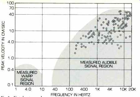
"Trackability" is the ability of the stylus to maintain contact with the record groove ... across the frequency spectrum found on records. In addition to record modulation, many other signals are present on records in the form of unwanted disturbances. Our study of record warp characteristics shows that the distribution of these disturbance signals extends into the sub audible region (Fig. 1). By including warp signals, we can refer not only to the trackability demands of the pickup, but also to that of the tonearm and cartridge "system." An example of the use of this procedure is shown in Fig. 2 for the V15 Type Ill in an SME arm at one gram tracking force. At frequencies where the trackability curve passes beneath the top limit of the signal distribution, the potential for mistracking exists. On records which contain these high peak signals, the V15 Type III, which possesses one of the highest high-frequency trackability of any present-day phono cartridge, should be played at its maximum recommended tracking force (1.25 grams) to track all signal levels. The remainder of the curve shows a trackability margin, illustrated by the clearance between the cartridge trackability curve and the shaded signal regions. Having a large track ability margin over only part of the frequency spectrum does not mean that the tracking requirement has been satisfied. Ideally, a reasonable track ability margin should extend across the entire frequency spectrum.
The dip in the trackability curve of Fig. 2 is due to a resonance between the tonearm equivalent mass and cartridge compliance. The graph shows a significantly reduced tracking margin in the warp signal region (below 10 Hz). The curve in Fig. 2 suggests two regions where such trackability improvements would be desirable. The first is in the mid- and high-frequency regions, and the second is in the cartridge-tonearm resonance region where only a limited margin exists.
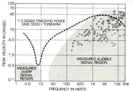
Fig. 2-The V15 Type III phono cartridge system trackability.
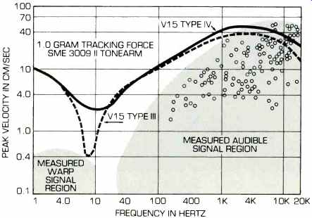
Fig. 3-The V15 Type IV phono cartridge system trackability.
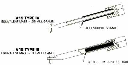
Fig. 4-Phono stylus comparisons.
The goal for the V15 Type IV was to achieve improvements in both of these regions without compromising other specifications. The objective was to avoid giving up any low-frequency trackability for a gain at high-frequencies or an increase in the warp-signal rejection. A "brute force" approach often used is simply to over-damp the stylus and increase the rated stylus force. This approach was considered unacceptable. It was also considered unacceptable to trade off a flat frequency response for the sake of improved high-frequency tracking. It is only through this no-compromise approach that a real improvement in trackability can be achieved, not just a rearrangement within the present constraints. Significant improvement in tracking ability was achieved as illustrated in Fig. 3 and Table I.
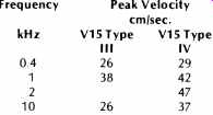
Table 1: Mid- and high-frequency trackability at 1-gram tracking force.
The greatest improvements were achieved in the high-frequency audio range and in the sub-audible warp signal region. In the low audio frequencies, below approximately 100 Hz, the performance of the V15 Type IV is similar to the V15 Type Ill and, as the figure indicates, is more than adequate for commercial records. The dramatic improvement in the lower frequency region indicates a new, significant margin of protection against warp signals. The significance of this will be explained later.
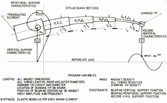
Fig. 5-Phono stylus model used in computer simulation.
We will now consider the means whereby improvements in the 20 Hz to 20 kHz range were achieved.
New Shank and Magnet Assembly
In a moving-magnet phono cartridge, the shank and magnet assembly is the heart of the transducer, and the design must evolve through a careful optimization process. It is necessary to have objective criteria which include low equivalent mass, a stylus resonance frequency above the audible range, low resonance Q resistance to bending and fracture, and the proper geometry with respect to the stationary elements of the transducer to insure accurate signal transduction.
Since many of these items lead to conflicting requirements, no one of these features can be maximized independently without affecting the others, or a less-than-optimum design would result. The engineer must evaluate each of these technical design factors and optimize them.
In the design of the V15 Type IV shank, a study was made that mapped out various aspects of the performance criteria. Through new computer techniques, many different shanks could be compared with respect to equivalent mass, impedance, flatness of response, stiffness, and physical geometry. Based on these results, many prototypes were constructed, measured, and subjected to extensive listening tests. The final design is called the "telescopic" shank and is shown in Fig. 4.
The telescopic shank employs a precision outer reinforcing tube in intimate contact with the shank. To achieve this critically tight assembly, new processes and highly specialized tooling were developed. The magnet is of a high-energy material that is reduced in both size and mass. By comparison, the V15 Type III uses a slightly larger diameter shank and an internal solid beryllium rod reinforcement. The net effect of these changes over the V15 Type III was to reduce the overall mass and equivalent mass of the stylus shank assembly, while maintaining similar overall geometry and bending strength. In terms of the performance criteria, the contribution of the new shank represents an improvement in high-frequency trackability, while maintaining a flat frequency response.
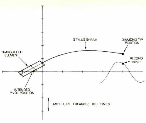
Fig. 6-Phono stylus simulation--example 1.
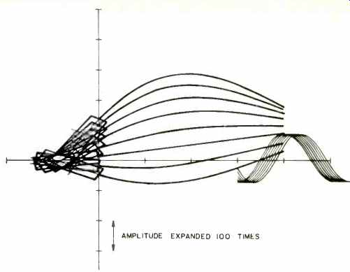
Fig. 7-Phono stylus simulation--example 2.
New Computer Model for Shank Evaluation
Although a new shank design is relatively easy to illustrate, the development of the shank was not an easy process. The description of one aspect of the project, a new computer model, which was used in the development of the V15 Type IV, will give some insight into the extensive engineering efforts behind such a development. The computer model is not an electrical mechanical analog as discussed in past literature. The model is a mathematical derivation of the dynamic system shown in Fig. 5.
The model allows for mass and stiffness distributions that vary over the length of the shank; in fact, up to four separate sections can be pieced together to form a composite system.
The supports, shown in the diagram as springs, represent record and bearing impedances which are each complex parameters determined from theory and empirical data. When given a sinusoidal input, the model can describe the stress or strain characteristics at any point within the system.
Figure 6 illustrates the type of information the program can produce. The figure shows the centerline of a simple tubular shank at an instant of time during vibration at its resonance frequency. In this example, shank and bearing motion is uncontrolled due to the system's relatively high mass and inadequate damping in the bearing supports. The center of rotation of the transducing element has vibrated away from its intended pivot position on the reference axis. Figure 7 illustrates positions of the same stylus system at sequential instants of time.
Note that in both Figs. 6 and 7 the vertical amplitude is shown magnified 100 times. The series represents 1/4 of a full cycle at the stylus resonance frequency. Observe the mistracking from the input sine wave, shank flexing, and again, magnet motion away from the pivot point.
The computer analysis shows that tracking requirements necessitate a shank configuration which minimizes flexing. The materials employed, the shape of the shank as well as its length, width, and wall thickness all must be considered. In addition, some means must be provided to prevent movement of the pivot point.
During the development of the V15 Type IV, over 50 theoretical assemblies were simulated on the computer, and many were selected and built as experimental prototypes. Of these, a two-element, telescopic stylus shank structure was chosen which best suited and matched the bearing and vibration absorber assembly.
Bearing and Damping System
Development of the stylus shank is closely related to the bearing and damping system. All elements must be carefully integrated to achieve an optimum design. In addition to the constraints imposed by the stylus shank material, it is the bearing or properties of elastomers in general that must be optimized to maximize trackability over the entire signal spectrum. For example, if the stiffness of the bearing is reduced, improvements in trackability at low frequencies are generally achieved, but these are offset by reductions in high-frequency track ability. Therefore, if significant gains are to be made, it is necessary to examine the nature of the bearing materials and their contribution to trackability.
An investigation of bearing material was undertaken to study the relationship of stiffness and damping of various elastomers over the sub-audible and audible frequency spectrum. Using what is referred to as a mechanical impedance transducer, it is possible to discriminate between the forces within the material which are primarily "spring-like" and those that most resemble a "dashpot" in character. A small cube of each material can be measured under stress/strain conditions that would be expected in the phono cartridge application. By measuring each test material over a wide range of frequencies, it is possible to generate the overall impedance characteristics of the material. By further processing this information, the dynamic stiffness and dynamic resistance characteristics of the materials can be determined. Thus, it is possible to measure the degree of both stiffness and damping as a function of frequency.
Ideal material qualities can also be defined. For example, the material should be stiff in the sub-audible region, compliant in the low- and mid frequency region, and then stiff again in the very high-frequency region-not an easy requirement to satisfy! However, it was found that by a special compounding process, these characteristics can be blended together to produce qualities that more closely approach the ideal.
The overall material impedance characteristic, a combination of both material qualities, provides a parameter that relates to system track ability. Looking at this function, the V15 Type Ill and V15 Type IV bearing material characteristics can be compared in the sub-audible to mid-frequency range (Fig. 8). This graph shows the V15 Type IV bearing to have higher impedance in the very low audible (below 100 Hz) and sub-audible frequencies, yet less impedance in the mid frequencies. This is a desirable characteristic since it maintains proper compliance for optimum cartridge-tonearm resonance frequency and provides for improved mid-frequency trackability. High-frequency track ability is optimized with the dynamic vibration absorber.
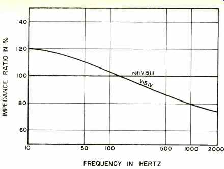
Fig. 8-Dynamic impedance comparison of the V15 Type III and Type IV bearing
materials.
The Dynamic Vibration Absorber
One of the compromises in designing the moving system of any phono cartridge has always been the conflicting requirements in achieving high trackability simultaneously in the low-, mid-, and high-frequency regions. As just stated, the demands upon the elastomer bearing are different for each part of the total spectrum. While the knowledge gained in measuring and blending the properties of elastomers allowed the engineer to more closely specify the optimum stylus system, it also showed that a single elastomer member, such as the conventional stylus bearing, could not ideally supply all the requirements over the entire frequency spectrum.
During the development phases of the Shure M24H Cartridge, designed for CD-4 quadraphonic as well as conventional stereo playback, there were additional requirements on the bearing to provide frequency response, track ability, and channel separation control through the carrier frequencies. It was at that time that Shure first applied the principle of the dynamic vibration absorber in a cartridge.
Figure 9 shows the initial embodiment of this approach in the development. A mass is attached to the end of the transducer magnet through a block of elastomer material, which has both the properties of compliance and damping. Above some preselected frequency, where additional damping is most beneficial, the mass element is such that its inertia prevents significant motion. The elastomer is vigorously exercised and its damping properties utilized. This effectively provides the additional damping only at the high frequencies where needed and not at low and mid frequencies where it is not desired.
Further exploration of the dynamic vibration absorber principle showed that a simpler, yet more functional, arrangement was possible. Figure 10 shows a structure which eliminates the lumped mass and takes advantage of the mass inherent in the elastomer itself. This distributed parameter structure allowed enhanced control of the initially conflicting compliance and damping requirements over the frequency spectrum. Its incorporation into the M24H design resulted in the desired carrier signal retrieval without record destruction while also allowing the M24H to perform as an excellent stereo cartridge.
The construction of the stylus and bearing system is shown in Fig. 11. The bearing and vibration absorber assemblies are designed to complement each other. The high-frequency mechanical resonance can be well controlled by the vibration absorber. With the bearing relieved of this function, it was possible to use a bearing material that improves tracking in the low- and mid frequency regions. In the past, both of the functions were performed by a single part, but now each function can be independently optimized. One function of the support wire is to locate the fore and aft position of the pivot by preventing longitudinal stylus motion.
Frequency Response, Separation, and Loading We feel very strongly that a flat response is ideal for a phonograph cartridge. Flat response in a linear system means that the output of the system is an exact reproduction of the input.
This is a highly desirable objective in phonograph reproduction, for it assures the cartridge will be a neutral link in the audio chain. The curve shown (Fig. 12) is the typical response of the V15 Type IV. Also shown are the tolerance limits. Each cartridge is individually tested to ensure that this specification is met.
The proper loading to achieve this response is 47 kilohms, 250 pF. This is a change from previous Shure stereo cartridges in that the recommended capacitance has been reduced. This value of capacitance is typical of that available in present-day preamp inputs plus tonearm wiring. Use of the exact capacitance value is not critical since a range from 150 pF to 350 pF will keep the typical response within the published specifications. Therefore, in the vast majority of applications, response within the limits shown can be obtained without any adjustment.
All cartridges meet a specification of 25 dB minimum (30 dB typical) channel separation at 1 kHz and 15 dB minimum (20 dB typical) at 10 kHz.

Fig. 9--Lumped-parameter stylus construction.
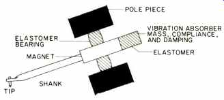
Fig. 10--Distributed-parameter stylus construction.
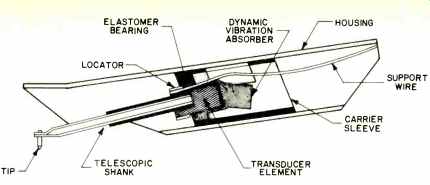
Fig. 11--V15 Type IV stylus assembly.
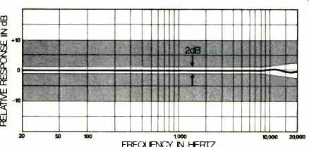
Fig. 12-The V15 Type IV typical frequency response envelope.
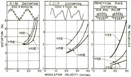
Fig. 13--Comparative distortion data with the Shure TTR 103 test record
and the stylus force at 0.75 grams.
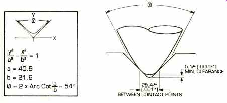
Fig. 14--Hyperelliptical stylus tip frontal profile.
Distortion
Distortion arises from many possible sources. We have discussed mistracking, the most serious cause of distortion and have described how it can be minimized through high trackability.
Figure 13 shows three types of distortion for the V15 Type II, Ill, and IV. Note that in all comparisons an improvement was achieved by each successive cartridge.
Two significant sources of distortion are the result of imperfect tracing and the mismatch of tracking angles.
Tracing Distortion
This type of distortion relates to the size and geometrical configuration of the tip. Here we will only summarize some significant conclusions. Four criteria were considered: tracing distortion, tip life, record wear, and noise generation. Distortion decreases as the tracing radius of the tip is reduced. The limit to size reduction is reached when the record wear and noise increase significantly. Record wear is also related to tracking force and, very significantly, to trackability. Thus, there are several interlocking considerations.
Our tests indicate that the minimum practical tracing distortion at this time is that which results from the use of a playing radius of 0.0002 inch (5 microns). In order to employ such a playing radius, tracking capability must be very high and tracking force must be lower than 1.5 grams. The maximum tracking force for the V15 Type IV is specified at 1.25 grams, well below the desired maximum of 1.5 grams. At this time we have no measured evidence that the use of a long contact-area stylus can allow this criterion (i.e. playing at over 1.5 grams) to be exceeded without affecting record life.
The requirements of a tip for the V15 Type IV were considered in the examination of tips of many geometries.
A variety of requirements for performance, including low distortion, noise, and wear, resulted in the design of the hyperelliptical tip (Fig. 14).
The Hyperelliptical Tip
There is nothing that is harder and more wear-resistant than natural diamond. These hyperelliptical tips are made from gem-quality, natural diamonds, i.e., they must be of high purity and be free of inclusions or crystalline defects. This ensures that they will survive the high stresses applied during the many manufacturing operations necessary to achieve the critical contour and side radii and will also provide a relatively low wear rate during playback.
The basic frontal contour is a hyperbola described by y^2/40.9^2 x^2/21.6^2= 1 (Fig. 14). It is generated by a manufacturing process involving intersecting cones. The frontal contour is approximately equal to 38µ (0.0015 inch) radius in the groove contact region.
The curvature has been carefully optimized and allows a certain degree of freedom for angular tolerances without degradation of performance.
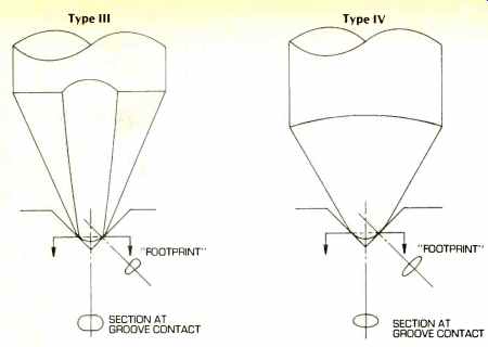
Fig. 15-Comparison between the V15 Type III bi-radial tip and the V15 Type
IV hyperelliptical tip.
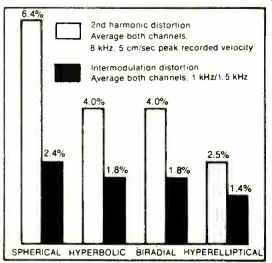
Fig. 16-Harmonic and intermodulation distortion for various tip shapes.
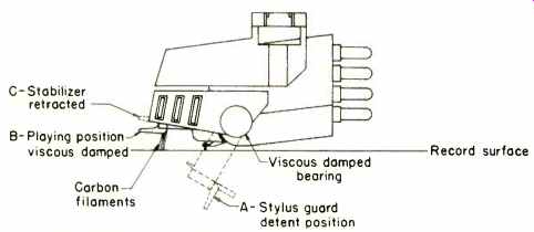
Fig. 17-Destaticizer stabilizer positions.
A minimum clearance of 5.1µ (0.0002 inch) from the bottom of the groove is required. The tip must never "ride" in the bottom of the groove since this will result in objectionable noise. The elongated contact area permits a narrower, but longer "footprint" in the groove wall, thereby reducing distortion (Fig. 15). The tracing radius is smaller for lower tracing distortion (Fig. 15), and it has an elliptical cross section that assures uniformity along the contact length.
The tracing radius is also smaller throughout, not just at the theoretical point of contact. By virtue of a patented manufacturing technique, the contact radius remains uniform along the entire contact length, an improvement over spherical, bi-radial, and some of the conventional long-contact varieties. The desired geometry is a natural outcome of the manufacturing process. Notice that, even though the tracing radius is smaller, the contact area is not; it is just shaped differently. Therefore, we have the advantage of more accurate tracing without decreasing the contact area.
This is an important point in that the contact area is related to the amount of indentation and stresses within the groove wall, which probably influence record wear.
Measurements
The design just described satisfies several functional and practical manufacturing requirements. However, the tip must be tested in the cartridge itself to determine whether it performs dynamically. Extensive testing is done to check the design and performance under dynamic conditions. This type of testing includes distortion measurements, noise and wear measurements, and visual observations of tips and records in conjunction with controlled tests.
A) Distortion Measurements: The dimensions of the hyperelliptical tip theoretically indicate that it will trace the signal more accurately than its predecessors. Tests performed which verified this are as follows (Fig. 16):
1) Second harmonic distortion was measured using the V15 Type IV cartridge with the CBS STR-100 test record on bands 3A and 3B with a 8-kHz signal 5 cm/sec. peak velocity at a tracking force of 1.25 grams. Average values of both channels for several cartridges are as follows: a) spherical (0.6 mil), 6.4 percent; b) bi-radial (0.3 x 0.7 mil), 4.0 percent; c) hyperbolic, 4.0 percent, and hyperelliptical, 2.5 percent.
2) IM distortion was measured with the V15 Type IV cartridge on the TTR103 test record, band 6, with a 1 & 1.5 kHz signal @ 25 cm/sec. peak velocity at a tracking force of 1.25 grams. Average values of both channels for several cartridges are as follows: a) spherical (0.6 mil), 2.4 percent; b) biradial (0.3 x 0.7 mil), 1.8 percent; c) hyperbolic, 1.8 percent, and hyperelliptical, 1.4 percent.
These data show two different types of distortion measurements under two different sets of conditions. The numbers change, but the trend is clearly the same. The hyperelliptical tip yielded lowest distortion values in each case. Since the tests were conducted under different conditions, there is a strong indication that the results are not unique to one case but are valid for a wide variety of situations in which a valid difference would result.
In all of the preceding measurements, great care was taken to assure that the test conditions remained the same for all styli. Tracking force and skating force were set for each stylus.
A new record was used for every stylus.
The measurements were repeated to demonstrate that the results were repeatable and consistent. All of these precautions must be taken to obtain meaningful data that is repeatable.
Even with these precautions, we still occasionally find individual styli that do not fit the pattern. We must remember that distortion measurements are measuring more than just the distortion caused by the tip. Therefore, it is necessary to test many units in order to arrive at valid conclusions.
B) Noise Measurement: Tests were conducted to determine the effect of the hyperelliptical tip on surface noise.
The cartridge was a V15 Type IV on a 33 1/3 rpm record with a radius of 3 inches, tracking unmodulated (silent) grooves with a tracking force of 1 gram using a high-pass filter from 500 Hz with the frequency response on each stylus equalized to be like all other styli within 1 dB. The results for average wide-band noise output on initial play on both channels for several cartridges relative to the 1-kHz level @ 5 cm/sec. peak velocity were a) biradial (0.3 x 0.7 mil), -46% dB, and b) hyperelliptical, -47 1/2 dB. The above difference is not significant and shows that the hyperelliptical generated about the same acceptably low surface noise as the conventional biradial tip.
C) Wear: Comparative tests were conducted to evaluate tip and record wear. In one test V15 Type IV styli with biradial, hyperbolic, and hyperelliptical tips were played continuously on the Shure TTR110 record at 1.25-grams tracking force. All cartridges were mounted in the same model record changer. The tips and records were cleaned regularly. Based on photographs of the tips, no significant difference in the rate of tip wear was observed in these tests.
Record wear tests were conducted as well. Second harmonic distortion was measured after 100 plays. The results showed no significant difference among biradial, hyperbolic, and hyperelliptical tips.
Although extensive testing has been performed on noise generation, record wear, and tip wear, we have found little in the way of significant differences among tips of different shapes. We have confirmed that playing at higher tracking force accelerates wear and recommend a force of no more than 1.5 grams. We have also confirmed, once again, by measurement that mis tracking is disastrous in terms of noise and record wear.
Tracking Angle Distortion
Of the two types of tracking angle distortion, that which applies to the cartridge relates to the vertical tracking angle (VTA). Much has been written on that subject but, unfortunately, no standard exists either in the way records are cut or in their method of measurement. Unofficially, a 15° VTA is called for in the U.S. and 20° in Europe. Without a standard measuring means, however, we cannot determine whether these angles are being employed in records or not.
Although a universal standard VTA for the cutting of records does not exist, we do specify the geometrical vertical tracking angle of the cartridge.
This is to be distinguished from the effective VTA of the cartridge during playback. The latter must best be determined by a suitable test record.
Since a standard, universally accepted test record does not yet exist, the only vertical tracking angle specification that can be stated with reasonable certainty is the geometrical vertical tracking angle. This angle may be derived from layout drawings and from measurements of actual piece parts in the assembly. The available test record means include a second harmonic distortion method--test record CBS STR-160, intermodulation distortion method-test record RCA 12-5-78, and intermodulation distortion method--test record DIN 45 542. Extensive measurements using each of these test records indicate significant differences among these techniques. Specifically, the RCA and DIN test records can yield measured vertical tracking angles as much as 5° higher than those obtained using either the geometrical method or the CBS STR-160 test record. In addition, a variation of approximately 3° is obtained from two different test bands on the DIN 45 542 test record. The geometrical vertical tracking angle of the V15 Type IV was designed not to exceed 23° to insure that it will meet the DIN specification of 20° +5°
Dealing With Non-Ideal Conditions
Our discussion has dealt with factors relating to playback under ideal conditions. We have also described how to improve trackability to handle extremely high-level modulation. As stated earlier, conditions are almost never ideal. We will now describe means of dealing with the major phenomena that create a non-ideal playing situation.
Cartridge-Tonearm Resonance, Warps, and Structure-borne Noise: An ideal method to control the cartridge-tone arm resonance should incorporate the following considerations: 1) the arm should be free to follow very low-frequency input-warps, spiral groove, banding, etc.; 2) the response of the system should include all program material and reject undesired outputs; 3) any damping system employed should suppress the resonance so that undesired low-frequency inputs are not magnified, and 4) the damping means should not affect the stylus centering when banding or groove pitch changes are encountered.
The Shure V15 Type IV provides a unique and practical solution to the problem of damping low-frequency cartridge-tonearm resonance. This has been accomplished in conjunction with several other features and without sacrificing any operating characteristics.
The system uses a structure called the Dynamic Stabilizer. The stabilizer, shown in Fig. 17, displays two unique features. The first is a graphite-filament structure located on the bottom front edge of the stabilizer, and the second is the viscous-damped bearing system which replaces the standard stylus-guard pivots.
Position "A" shows the stabilizer detented downward and functioning as a stylus guard. Position "B" is the normal playing position. The graphite filaments contact and "ride" the record surface, and the. viscous damping of the bearings controls the vertical resonance. Note that the stabilizer filaments are placed as close to the stylus as possible; this is a critical factor in insuring that motions from warps are applied to both the stylus and stabilizer simultaneously. The net result of this action is that the tonearm closely follows the irregularities of the record and minimizes warp effects on the stylus.
The V15 Type IV has a stylus tracking force range of 1.25 to 1.75 grams and the Dynamic Stabilizer exerts a 1/2 gram force on the record surface.
Thus, the total arm force is set between 0.75 and 1.75 grams. In position C, the stabilizer is retracted, and the fibers do not touch the record surface.
Record play in this case is in the conventional manner, and the tracking force is set for the stylus range of 1.25 to 1.75 grams.
The choice of small diameter graphite fibers was made for several reasons. In addition to excellent functional properties, such as a damping contact, the fibers are electrically conductive, picking up static electricity on the record surface and discharging it to ground. Because static electricity on the record can attract the arm and pickup, the fibers serve to stabilize the tracking force during record play. (The static discharge takes place-though less effectively-even when the stabilizer is in position C.) The graphite fibers also function quite efficiently as a record-cleaning brush. Each strand is only 7.6 microns in diameter, enabling it to sweep the record grooves free of loose dust and prevent the grinding of dust into the groove walls.
Still another feature of the stabilizer is its function as a shock absorber.
When the arm is accidentally dropped, a conventional stylus assembly receives the full shock upon contact.
Permanent damage may result and the stylus may even become inoperative.
In addition, the springiness of the stylus may cause it to bounce across the record and damage the grooves. In normal operation--i.e. position B--the viscous-damped stabilizer cushions the impact of the drop and prevents bouncing.
Thus, the V15 Type IV provides solutions to a number of phono equipment problems. The Dynamic Stabilizer not only effectively solves the problem of low-frequency stability, but also offers virtual freedom from static electricity, record surface dust, and impact damage.
Stabilizer Control of Cartridge-Tonearm Resonance: A convenient way to measure the effectiveness of the stabilizer is to run the low-frequency response curve. An STR-120 record played back at half speed will produce a sweep from 5 to 250 Hz, nicely covering the cartridge-tonearm resonance frequencies. The record is cut with a constant amplitude characteristic, and this is shown in Fig. 18 as the flat zero axis.
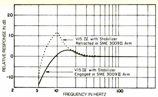
Fig. 18--Low-frequency vertical response of the V15 Type IV STR 120 @ 16 2/3
rpm through integrator.
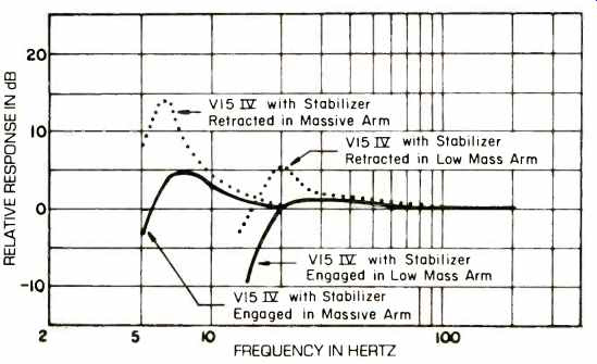
Fig. 19--Low-frequency vertical response of the V15 Type IV STR 120 @ 16 2/3
rpm through integrator.
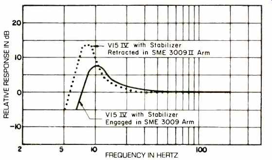
Fig. 20--Low-frequency lateral response of the V15 Type IV STR 120 @ 16 2/3
rpm through integrator.
The measurement is made through an integrator which causes the output of the cartridge to correspond to the amplitude of the relative motion between stylus and cartridge body. The dotted curve shows the response of a V15 Type IV in an SME arm Series II with the stabilizer retracted. Note that the arm resonance causes an 11-dB increase in output at 10 Hz. When the stabilizer is engaged, the peak is effectively damped to less than 3 dB. At still lower frequencies, the response falls off rapidly, corresponding to frequencies at which the cartridge-tonearm assembly moves as a whole.
In Fig. 19, the effects of mounting the V15 Type IV in both a very light and a very heavy arm are shown. The equivalent mass of the light arm without cartridge is about two grams, which is about the practical minimum.
Here, the stabilizer removes the 6-dB peak which represents the best that can be accomplished with a cartridge with a mass of five grams. The heavy curve is run in an undesirably massive arm, and even here there is a reduction of approximately 8 dB below the 14 dB that would otherwise be present.
An informal way of demonstrating the effectiveness of the stabilizer is to drop the cartridge on a record from a 1/2 inch height. The pickup will practically attach itself to the record at the point of first touchdown, instead of showing the bouncing, skating behavior observed with non-stabilized cartridges.
Since the stabilizer works principally in the vertical mode, it is not unexpected that the lateral resonance shows smaller changes, which are shown in Fig. 20. Even here, the effect of increased stiffness and damping may be seen as the response peak is shifted to a higher frequency with considerably less peaking. However, as mentioned earlier, the need for reduction of the lateral resonance is minimal compared to the need for vertical control, since a record would not have lateral warps and the structure-borne noise is principally vertical.
A critical factor in the design and application of the dynamic stabilizer is that of minimizing noise generation.
Several features were incorporated in the design to guarantee that noise would be insignificant. A specification of at least 6 dB below typical values of groove echo puts the noise well below the noise level of commercial discs.
Control of Static Electricity
As mentioned in Part I, variable attraction of the cartridge to the record can seriously effect sound quality.
Because static electricity is such a persistent and erratic problem, it was felt that the V15 Type IV should incorporate an effective means of nullifying its influence. The Dynamic Stabilizer incorporates a bundle of graphite fibers bonded to a metal carrier, which, in turn, is pivoted on the stylus grip. Thus, the fibers wipe the charges from the grooves which are about to be played. Care has been exercised to maintain a conductive path through the fibers, carrier, bearings, and stylus grip to cartridge ground. The surface of the record, therefore, is effectively grounded through the stabilizer during playback.
Even in the "up" position and not contacting the record, the fibers perform a destaticizing function, reducing the threshold voltage (see Part I) to about half the level it would otherwise attain. In playing position, the Dynamic Stabilizer reduces even a strong charge to negligible proportions in the course of playing a record. Since the carbon filaments are offset toward the center of the record, charges are removed before the stylus reaches the portion of the groove to be played.
A record initially charged on both sides and played on one side will experience a reappearance of the charge on the record's underside when it is removed from the turntable. This is due to the electrostatic field concentrated under the record while on the turntable and not available to the Dynamic Stabilizer.
In addition to destaticizing the playing surface, the graphite fibers are effective in sweeping dust particles from the grooves before the stylus reaches them. The absence of static charges makes the sweeping job much more effective than non-conductive bristles and their resulting charges would produce.
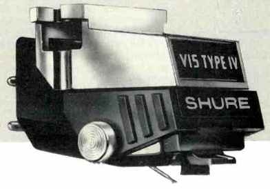
Fig. 21--The Shure V15 Type IV Stereo Dynetic phonograph cartridge.
Thus, we feel that our investigation has resulted in a phonograph cartridge system (Fig. 21) which effectively deals with the problems caused by static electricity. Eliminating discharges and electrostatic attraction-making dust and particle removal much more effective-and stabilizing the arm against spurious excitation have resulted in a significant improvement in record reproduction.
Summary and Comments on the Future
We have considered two aspects of phonograph reproduction, playback of the modulation in the groove under ideal conditions and the effects of practical, non-ideal conditions. Playback under ideal conditions presents some very challenging requirements including tracking over a broad dynamic range, reproduction of the complete audible spectrum, and maintenance of adequate separation for good stereo reproduction. These requirements must be fulfilled with a minimum of distortion, while at the same time providing a maximum of record and tip life.
As stringent as the requirements of playing back the modulation are, consideration must also be given to the practical conditions that exist in the normal, non-laboratory situation. We have described a phonograph cartridge system which offers a means of controlling the most significant practical problems, namely: 1) undamped low-frequency resonance excited by record warp and structure-borne noise, 2) the effects of electrostatic charges, and 3) dust and dirt on the record surface.
Extensive testing has shown that control of these conditions provides a significant improvement in phonograph reproduction.
(Source: Audio magazine, June 1978)
Prev: Phonograph Reproduction --1978: part 1 (May 1978)
Also see: A New Standard in Turntable Speed Constancy (June 1978)
= = = =
