Manufacturer's Specifications
FM Tuner Section
Usable Sensitivity: 11.2 dBf (2.0 µV/ 300 ohms).
Fifty-dB Quieting Sensitivity: Mono, 19.1 dBf; stereo, 39.5 dBf.
Signal-to-Noise Ratio: 70 dB minimum, both mono and stereo.
Harmonic Distortion: Mono, 0.18%; stereo, 0.38%, maximum.
Alternate Channel Selectivity: 78 dB minimum.
Image Rejection: 100 dB minimum.
Stereo Separation: 45 dB minimum at 1 kHz.
AM Tuner Section
Sensitivity: 75 µV (external antenna). Signal-to-Noise Ratio: 45 dB min. IHF or 55 dB @ 100% modulation.
Adjacent Channel Sensitivity: 30 dB minimum.
Image Rejection: 65 dB minimum from 540 kHz to 1600 kHz.
Frequency Response: +0,-6 dB from 20 Hz to 3.5 kHz.
Preamplifier Section Frequency Response: +0,-0.5 dB, 20 Hz to 20 kHz.
Rated Outputs: Main, 2.5 V; line, 1.25 V; headphone, 750 mV; tape, 250 mV.
Distortion: 0.02% max. @ 2.5 V output from 20 Hz to 20 kHz.
Input Sensitivity for 2.5 V at Main Out: Phono, 2.2 mV; high level, 250 mV.
Signal-to-Noise Ratio: Phono re: 10 mV in, 90 dB A wtd., 80 dB unweighted; high level re: 250 mV in, 100 dB wtd., 90 dB unweighted.
Input Impedance: Phono 1 and 2, 47 kilohms and 50 pF; high level, 47 kilohms.
Output Impedance: Main, less than 100 ohms; line, 600 ohms; phono, 8 ohms; tape, less than 200 ohms.
Equalizer Control Response:-±12 dB at 30 Hz, 750 Hz, and 10 kHz.
General Specifications
Dimensions: Panel, 16 in. (40.64 cm)
W x 5-7/16 in. (13.81 cm) H; chassis, 13 in. (33.02 cm) D; knob clearance in front of panel, 1 1/4 in. (3.17 cm).
Weight: 24 lbs. (10.8 kg).
Retailer Reported Price: $1,399.00.
McIntosh Laboratory Inc. remains one of the few companies that continues to offer a high-fidelity component which incorporates both FM/AM tuner circuitry and preamplifier control circuits. For those audio enthusiasts who do want to include radio (and particularly high-fidelity stereo FM radio)
as a program source in their audio systems, this combination, on a single chassis, makes a great deal of sense; so much so, in fact, that I have always wondered why most other manufacturers have not offered this type of component. After all, it permits the user to choose any power amplifier he or she requires, allows for the incorporation of two turntables as well as two tape decks, and offers the versatility of a separate preamp-control unit while at the same time incorporating a top performing stereo FM/AM tuner.
Front Panel Layout
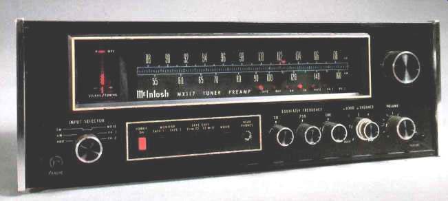
The MX-117 has the unmistakable McIntosh front panel look, with its anodized gold and black finish, gold/teal illuminated nomenclature, and exclusive PANLOC mounting system which has become a tradition on Mac equipment. A large, well illuminated cutout area of the panel contains the calibrated AM and FM dial scales, an evenly spaced "logging scale" (calibrated linearly in 0.1 increments from 0 to 10), seven small indicator lights (which denote program source selected as well as selection of interstation muting during FM listening), and a 14-LED solid-state tuning indicator system, consisting of 10 small dots arranged in a vertical row, a small bar which illuminates to denote stereo signal reception, and three bars which tell if you are tuned below, above or exactly to center frequency when listening to an FM station.
A conventional flywheel-coupled tuning knob is positioned to the right of the dial area. All remaining front panel controls are neatly arranged along the lower section of the panel. These include a six-position program source selector switch at the lower left (AUX, AM, FM, FM mute, phono 1, and phono 2), three tone controls to the right of center (McIntosh prefers to call them equalizer controls, since they do divide the audio spectrum into three parts, as opposed to simple bass and treble tone controls which usually control wider swaths of frequencies), a dual-concentric balance and loudness control, and a master volume control at the lower right. Six pushbutton switches, plus a stereo headphone jack, are located to the left of center of the panel. A red button serves as the power on/off switch, while the contrasting black buttons handle such functions as tape 1 or tape 2 monitoring, tape copying from either connected tape deck to another, and stereo/mono selection. The loudness control arrangement found on the MX-117 is different from any I have previously encountered, and I shall have more to say about its action presently.
Rear Panel Controls
Stereo pairs of input jacks and a chassis ground terminal are located at the extreme right of the rear panel of the MX 117. Inboard of these are two pairs of "Main" output jacks, line-out jacks (designed to operate into 600-ohm loads), the tape-out jacks (for connection to up to two tape decks), and vertical and horizontal oscilloscope output jacks which may be connected to McIntosh's Maximum Performance Indicator or to any oscilloscope for observation of multipath phenomena during orientation and optimization of an FM antenna. A pivotable AM loopstick ferrite antenna is located at mid-panel, and next to it is an FM preselector switch which introduces additional tuned-circuit filtering for additional r.f. selectivity in the event of strong-signal overload conditions. Normally, this switch is left in the "out" position.
External AM, ground, and 300-ohm FM antenna connection terminals of the "push to insert wire" spring-loaded type are at the upper right of the rear panel, and alongside is a standard coaxial connector for use with 75-ohm transmission lines. Three switched and two unswitched convenience a.c. outlets complete the rear panel layout. Up to 600 watts of power can be drawn from all of these a.c. receptacles, combined.
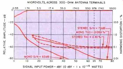
Fig. 1-Mono and stereo quieting and distortion characteristics, FM tuner
section.
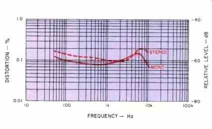
Fig. 2-Harmonic distortion vs. frequency, FM tuner section.
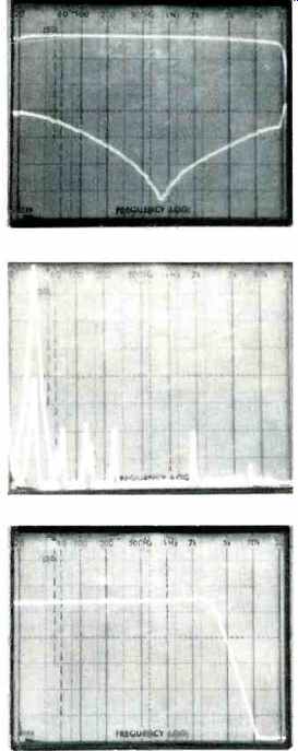
Fig. 3-Frequency response and stereo FM separation.
Fig. 4-5-kHz crosstalk components.
Fig. 5-Frequency response, AM tuner section.
Circuit Highlights
The FM front-end employs five sections of an 8-section variable capacitor (four, when the preselector switch is in the 'but" position). As with most of the switch functions of the MX-117, even the preselector switching is accomplished electronically, with a d.c. voltage controlling pin semiconductor diodes which do the actual switching. Front panel selector switching, for example, simply switches control voltages which turn FET analog switches on or off. Since the actual switches are located near the input jacks, pickup noise and high-frequency losses are minimized compared with conventional mechanical switching arrangements.
A double-tuned MOS-FET r.f. amplifier and a balanced MOS-FET mixer are used in the FM front-end. A MOS-FET buffer amplifier is used between the local oscillator and the mixer. The oscillator is fine tuned by a varactor diode operated by á correction voltage derived from a patented McIntosh circuit called Automatic Frequency Lock (AFL) which turns on a "lock" voltage when perfectly centered tuning has been reached.
The FM i.f. section uses five integrated circuit amplifier and four piezo-electric filters, for a total gain of 140 dB. A full Foster-Seeley discriminator (as opposed to the more common Ratio Detector discriminator) completes the i.f. system. The composite demodulated signal feeds the stereo FM multiplex section, the heart of which is a new type of phase-locked-loop stereo decoder IC. This IC incorporates an automatic variable-separation control (to reduce background noise during weak-signal stereo reception) and tri level digital waveform generation (which eliminates interference from SCA signals and from the sidebands of adjacent channel FM signals). Suppression circuits for 19 and 38 kHz are used to attenuate any residual carrier components following multiplex decoding. The FM muting circuit employed in the MX-117 operates by detecting ultrasonic noise and by sensing correct center tuning of the detector circuit. Muting of the audio signal is done with a positive acting FET switching circuit.
The AM tuner section employs a three-section tuning capacitor and a special AM r.f. amplifier which maintains constant selectivity, constant sensitivity, and high image rejection across the entire AM band. An autodyne circuit is used for the AM mixer, and two double-tuned transformers are used in the AM i.f. section. A 10-kHz "whistle filter" is included in the AM tuner section, as is a two-section AVC filter for lower distortion at bass frequencies.
The phono preamplifier-equalizer section uses an IC operational amplifier whose differential input stage has been optimized for low noise and low distortion. The feedback network, which also provides RIAA equalization, employs 1% metal film resistors and 5% polyfilm capacitors.
The gain of this preamp section is just over 41 dB. As for the unusual loudness control arrangement referred to earlier, it uses the same sort of IC operational amp as in the phono preamp stages. Two feedback loops are employed, one flat, the other conforming to the Fletcher-Munson equal loudness contours. A potentiometer (the front panel "Loudness" control) placed between these loops makes it possible to select any curve from flat response to full loudness compensation. Once the contour is set by the user, it remains fixed and independent of the position of the master volume control. The equalizer-amplifier also uses a low noise operational amplifier. Three other op-amps are arranged in the circuit equivalents of three tuned circuits, each resonant at one of the three equalizer center frequencies.
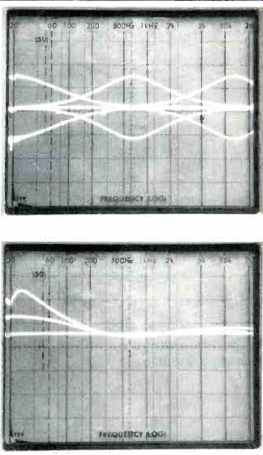
Fig. 6-Control range of bass, midrange, and treble equalizer controls.
Fig. 7-Response obtained with various settings of the continuously variable separate loudness control.
The output amplifier of the MX-117 is a push-pull, complementary Class AB circuit which uses a signal-inverting differential stage at its input. The amplifier drives the main and line outputs as well as the headphone jack. A turn-on delay circuit, using a light-emitting diode/light dependent resistor network that transmits no signal for two seconds after power is applied, also operates to turn off signals almost instantly when power is turned off. This arrangement serves to keep turn-on and turn-offs of the tuner-preamplifier transient-free.
The power transformer of the MX-117 is triple shielded (copper strap, silicon steel strap, and steel outer shell) for minimum hum and radiation. A full-wave bridge rectifier with 3330-µF filter capacitors provide the d.c. voltages which are applied to positive and negative supply regulators. The dual-polarity 18 volts of d.c. needed for the low-level amplifier stages are supplied by IC regulators.
FM Measurements
Figure 1 is a multiple plot of mono and stereo quieting characteristics and mono and stereo total harmonic distortion characteristics (at 1 kHz) of the FM tuner section of the MX-117. Usable sensitivity in mono measured 10.8 dBf (1.9 µV, 300-ohms) or a bit better than claimed, while in stereo, usable sensitivity was determined by the stereo switching threshold, which occurred at 15 dBf (3.1 µV). The more important 50-dB quieting point was reached in mono at a very low signal strength of only 12 dBf (2.2 µV), while in the stereo mode, that degree of quieting was reached at a signal input level of only 27.5 dBf (13.0 µV), about as low as I have measured for any stereo FM tuner. McIntosh, as usual, continues to give ultra-conservative specifications.
For the MX-117 they claimed only a minimum of 70 dB of signal-to-noise ratio in mono and stereo FM. In fact, the unit tested produced S/N of 83 dB in mono! Even in the stereo mode, where S/N is generally poorer, I still obtained a reading of 78 dB for an input of 65 dBf (approximately 1000 µV); with somewhat stronger signals, the S/N improved even further, to 80 dB! Distortion, too, was considerably better than claimed by McIntosh. Under strong-signal conditions (standard test conditions at 65 dBf), harmonic distortion for a 1-kHz signal at 100% modulation measured 0.086% in mono and almost as low, 0.10%, in stereo. Nor was this low level of distortion limited to mid-frequencies, as can be seen in Fig. 2, which plots distortion as a function of modulating frequencies.
In Fig. 3, a 'scope photo of a spectrum analyzer multiple sweep, the upper trace represents output from the left channel main output with a left-only signal modulating my FM generator and sweeping from 20 Hz to 20 kHz. The lower trace was obtained by subsequently measuring the output of the right channel under the same modulation conditions, and it is therefore a measure of stereo separation versus frequency. The vertical scale is 10 dB per division in this and all other 'scope photos. At 1 kHz, separation measured an impressively high 55 dB (as opposed to McIntosh's conservatively guaranteed 45 dB); at the frequency extremes of 100 Hz and 10 kHz I measured 37 dB and 35 dB respectively. In Fig. 4, the sweep mode was changed, so that this time the sweep was linear from 0 Hz to 50 kHz, with the lightly visible scale corresponding to 5 kHz per horizontal division. The tall spike at left is a 5-kHz output from the modulated channel. Contained within that spike is the representation of the opposite (unmodulated) channel output, while to the right of these are various crosstalk products at harmonics of 5 kHz as well as any residual 19-kHz or 38-kHz subcarrier output products. All of these extraneous output products were at least 60 dB or better below the desired reference output level. Note, too, that separation at the relatively high 5-kHz frequency was approximately 40 dB (the difference in "height" between the two spikes at 5 kHz-one within the other-at the left of the display). Muting threshold was set to 17 dBf (3.9 µV), an ideal signal level for this type of muting circuit since it allows the listener to enjoy reception of marginally quiet signals while still benefiting from the interstation muting feature. I measured an alternate channel selectivity of 80 dB for this sample. SCA rejection, under conditions of a modulated 67-kHz SCA subcarrier injected at 10% of total modulation of the main carrier, was a very satisfactory 60 dB below reference output level; stereo subcarrier product rejection was in excess of 65 dB. Although it is not my practice to spend too much time testing the AM sections of AM-FM tuners (most of them are simply so poor in performance they are not worth bothering about), I do, as a matter of course, measure at least the frequency response. As can be seen in Fig. 5, I was pleasantly surprised to find absolutely flat response down to 20 Hz (most AM tuners tend to roll off bass severely below 50 to 100 Hz or so). While response to 3.5 kHz may not seem like "hi-fi" reproduction to most listeners, it is actually better than the result obtained from most of the AM sections of combination AM-FM tuners or receivers that I measure.
Preamplifier and Control Section Measurements
McIntosh Laboratory has chosen to publish their specifications relating to the audio portions of the MX-117 in a way that predates the new IHF/EIA Amplifier Standards, whereas I adhere to the newer Standards. Since this would make it difficult to compare published specs with my test results, I decided to make both types of measurements. In that way, readers interested in comparing results to those obtained for other products where the IHF/EIA standard was used will be able to do so, and anyone wishing to compare results with McIntosh published specs can do so as well.
IHF/EIA phono input sensitivity measured 0.45 mV. This corresponds to almost exactly 2.2. mV as claimed by McIntosh for the higher 2.5-volt output. As for the high-level inputs, 50 mV of signal was required to deliver the reference 0.5-volt output, and this too corresponds exactly to the 250 mV spec called for by McIntosh for their referenced output level of 2.5 volts.
Figure 6 illustrates the range of control of each of the three equalizer controls provided on the MX-117. The frequencies at which the three equalizer controls are centered make for an extremely versatile range of control. The action of this unit's unique loudness control is illustrated in the series of response curves plotted by means of a spectrum analyzer and reproduced in the 'scope photo of Fig. 7. Note that only a moderate amount of treble compensation comes into play as the control is advanced towards more contouring of the signal.
Frequency response of the phono preamp-equalizer section of the MX-117 was plotted using a Sound Technology 1500A test instrument and an associated video printer. In Fig. 8 we see the familiar RIAA playback curve obtained by feeding a constant amplitude, swept-frequency signal into the phono inputs. The plot extends from 20 Hz at the left to 40 kHz, with double vertical lines indicating 100, 1000 and 10,000 Hz. The 0-dB reference has been established at 1 kHz, as shown. In Fig. 9 the vertical sensitivity of the plot has been expanded so that it is 2 dB per vertical division (instead of 10, as in the previous display). Also, the signal applied to the phono inputs has been subjected to inverse RIAA equalization so that, in theory, if perfect RIAA equalization were incorporated in the MX-117, a straight line would be obtained. As you can see, maximum deviation from this ideal was 0.6 dB at 40 Hz (where the dotted line cursor is positioned for a readout at the lower right of the display); moving the cursor to the maximum deviation in the high-frequency region produced a maximum deviation from absolute RIAA accuracy of only 0.5 dB at 18.5 kHz.
Signal-to-noise ratio of the phono section was first measured in accordance with the IHF/EIA standard, which calls for a 5-mV input at 1 kHz and adjustment of the volume control so as to produce an output of 0.5 volt. Under these conditions, and using an A-weighting curve, a reading of 84.4 dB was obtained. Spectral distribution of the noise, in one-third octave bands, is plotted in the frequency/amplitude grid of Fig. 10. When I adjusted input and output levels to correspond to the measurement method used by McIntosh (10 mV of input), a repeat of the S/N measurement plot as shown in Fig. 11 yielded a ratio of 91.9 dB, fully 2 dB better than claimed. Signal-to-noise ratios obtained via the high-level inputs (AUX 1, AUX 2, or Tape) were above 100 dB, or beyond the 1500A test instrument's measurement capability.
Distortion of the amplifier section measured far below the minimum specification supplied by McIntosh. For an input level of 250 mV (high-level inputs) and an output of 2.5 volts, THD measured 0.0017% and 0.0018% at 1 kHz for the left- and right-channel outputs respectively. For a 20-Hz signal input, results were 0.005% and 0.0049%, and for a 20-kHz input signal of the same amplitude, the distortion readings were 0.003% for either channel. Phono overload measured an acceptable 105 mV at 1 kHz. Overall frequency response was down by-1 dB at 14 Hz and 41 kHz, while the-3 dB points were observed at 10 Hz and 78 kHz.
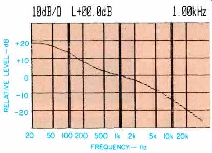
Fig. 8-Phono section response, using a constant input.
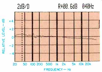
Fig. 9-Phono section response, using an inverse RIAA input. Note the expanded
scale.
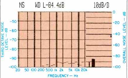
Fig. 10-Phono S N measurement, using IHF/ EIA input and output reference
levels.
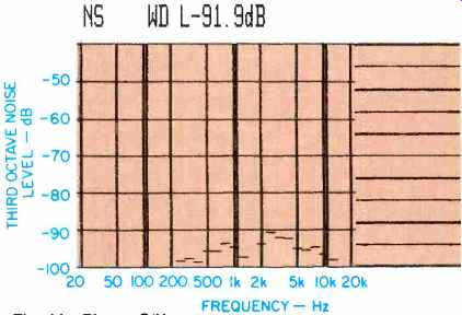
Fig. 11-Phono S N measurement using McIntosh input level reference of 10
mV.
Use and Listening Tests
As usual, McIntosh has come up with another fine high-fidelity component in the MX-117. The design is extremely well balanced such that all sections of the product seem to work equally well. The FM tuner section was very sensitive.
The stations I normally expect to receive with little audible background noise (plus a few I don't often receive in "listen able" fashion) came through nicely, and dial calibration was as close to perfect as any I have seen-from one end of the dial to the other. The Automatic Frequency Lock circuit, for all its fine "hold" on the stations I tuned to, did not prevent me from zeroing in on weak stations that were located very close to stronger ones-a complaint often lodged against less sophisticated forms of a.f.c. circuitry. Stereo separation was excellent, and even when I expected to hear background noise when tuning to certain familiar weak stereo stations, the noise was far less obtrusive than expected.
This, no doubt, was thanks to the inclusion of the automatic stereo noise suppression circuit with its variable stereo separation circuitry.
The phono preamplifier circuitry produced no audible hum or noise even when reproducing extremely soft passages from records having wide dynamic range. There was also no evidence of overload during peak groove excursions in audiophile records which I auditioned on the MX 117. Bass reproduction was tight and completely unmuddied and open. Treble tones were reproduced with no trace of harshness or fuzziness and with excellent transient signal clarity.
To all of these attributes must be added the intangible qualities of durability, care in assembly, and the almost custom craftsmanship which distinguish all McIntosh products. Most McIntosh equipment owners consider these non obvious qualities to be worth fully as much, if not more, than the more obvious features found in equipment made by their favorite hi-fi component maker. Under those circumstances, what appears to be a relatively high price for this tuner-preamplifier may be a bargain, after all.
-Leonard Feldman
(adapted from Audio magazine, Jun. 1982)
Also see:
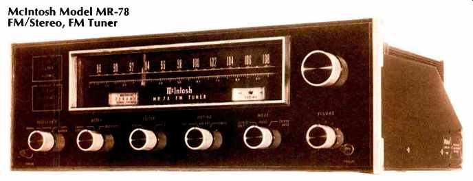
McIntosh Model MR-78 FM/Stereo, FM Tuner (Equip. Profile, Feb. 1977)
Mission 776 Preamp (Jun. 1982)
= = = =