MANUFACTURER'S SPECIFICATIONS:
Maximum reel size: 7 in. Speeds: 7 1/2, 3 3/4, and 1 7/8 ips.
Heads: Erase, Record, Playback, and Crossfield Bias.
Motor: Hysteresis-synchronous.
Erase and Bias Frequency: 85.5 kHz.
Inputs: Mic, Line, Phono (magnetic or ceramic).
Frequency Response: 7 1/2, 40-20,000±2 dB; 3 3/4, 40-16,000±2 dB; 1 7/8; 40-9000±2 dB.
Wow and Flutter: .07% at 7 1/2; 0.14% at 3 3/4; 0.28% at 1 7/8.
Signal-to Noise Ratio: 54 dB, unweighted.
Dimensions: 15 1/2" L, 12 3/4" D, 6 1/2" H.
Weight: 21 lbs.
Price: $499.00
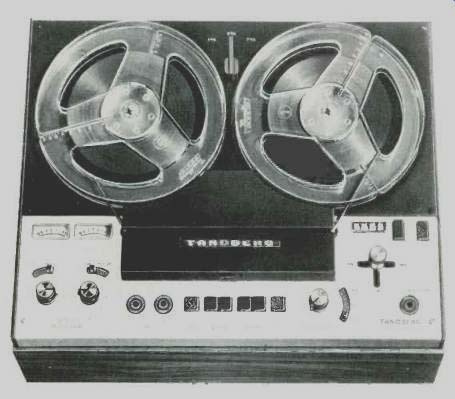
It seems as though every new product from any of the reputable manufacturers has more new features than the previous model, as would be expected. Similarly, performance also seems to get better with each new model. Such is the case with the Tandberg 6000, which continues the use of crossfield biasing, provides meters, allows for direct recording from a phono cartridge, as well as from microphone or line sources, includes a limiter, and for the first time incorporates a pushbutton start facility, and permits making sound on-sound, "add-a-track," and echo recordings.
The control panel is complete on the lower portion of the deck, assuming it is used in the vertical position. At the left are the two record-level meters, illuminated during recording. Below are the dual concentric record-level controls, with a switch lever protruding through the panel to permit selection of line or phono for the lower control, while the upper control knob serves for the microphone. Next to the right are two phono jacks for microphone inputs.
Six switches follow in the progression across the control panel. The first is a push-push LIMITER switch, followed by the left and right RECORD buttons, which lock when the tape motion lever is placed in the run position, and release when the machine is stopped by the tape motion lever, though not by the START/STOP but ton, about which you will learn later. The two push-push playback buttons follow--in the depressed position, you monitor from the tape; un-depressed, from the source. Next comes the dual-concentric playback level control, followed by a switch lever moving in an arc around the playback level control, and having three positions--AB TEST, NORMAL, and S ON S. In the AB TEST position, one can monitor from one channel and sing along with the program into the microphone, recording the mixed new program on the other channel-the usual sound-with-sound procedure. In the s ON s position, one can reproduce one channel and record on the other, with no cross feeding. The NORMAL position is used when no special effect is desired-the conventional two-channel recording operation. Next to the right is the stereo headphone jack.
Above is the usual Tandberg tape motion control lever, in the familiar "T" configuration, except that it also has a position upward which frees the reels from each other for ease in threading.
Above this lever is the four-digit counter, and to its right the counter reset button and the a.c. power push-push switch.
The speed control is at the top of the panel, and it moves the idler mechanically to change speeds, and simultaneously switches the record and play equalization in the two channels at the same time.
The START/STOP button, also a push-push switch, energizes a solenoid which operates as a pause control. Once the tape-motion lever is operated, the tape is started or stopped by operating the button-a particularly desirable improvement.
All connections to the recorder except microphone inputs and headphone output are made on the rear panel-or the top, if the machine is used in the vertical position. There is a four-terminal socket for a remote foot control, which parallels the STOP/START button in effect. There is an outlet for external equipment, such as the FM-MX filter which requires a 26-V d.c. supply, and which filters out the pilot and the 38-kHz switching frequency from those receivers or tuners which do not have sufficient internal filtering, which is a rarity in modern equipment, of course. The filter is available as an accessory when required.
In addition, there are three "DIN" sockets for direct connection to receivers or amplifiers so equipped-one for recording or playback from the radio or amplifier, one for connection to magnetic, ceramic, or crystal pickups ( with a separate switch for selection of type of pickup), and one for output to connect to another tape recorder for copying.
There are also three pairs of phono receptacles for line or pickup inputs and for the line outputs, as well as a seventh phono receptacle for a derived center channel output. Four large "buttons" serve to wrap the power cord around, and a sliding cover fits over the panel to obscure the cables and connections when the machine is used in the vertical position.
The Circuits
The phono selector switch introduces sufficient attenuation in the ceramic/ crystal position to match the inputs to a certain extent, while the LINE/PHONO switch on the front panel changes the gain and equalization of the three-transistor preamplifier section. This section is followed by the limiter, which consists of three bipolar transistors and an FET. When switched in, the limiter will give the same output, within 2 dB, over a 40-dB range of input levels, albeit with some increase in distortion. The waveform begins to square off as level is increased, unfortunately, although it does prevent large overloads. The limiter is followed by the three-transistor booster, which feeds the equalized recording amplifier, also utilizing three transistors.
Two additional transistors serve to drive the indicator meters, and three more serve as a playback amplifier, followed by three pairs of transistors in playback boosters-one for each channel and one for the derived center channel. Five more transistors are used for the oscillator, three more in the power supply, and one in the START/STOP circuit--a total of 57 transistors (of which two are FET's ), 14 diodes, and 3 Zeners. In all, it is a well designed, conservative circuit which performs well.
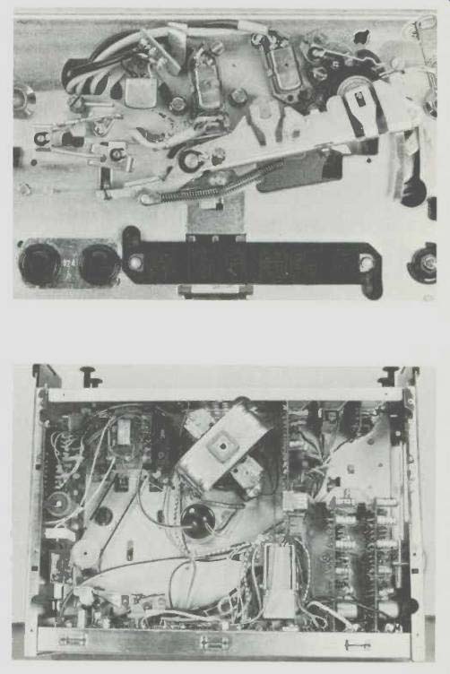
Fig. 1--Showing heads and capstan. Fig. 2--Underneath view.
Performance
The ultimate test of any tape recorder is in how it performs-frequency response, wow and flutter, and signal-to-noise ratio. The frequency response from standard tapes at 7 1/2 and 3 3/4 ips is shown in Fig. 3 in the top two curves, while the next three show the response in and out at all three speeds. The bottom curve shows the deviation from RIAA response from a magnetic cartridge playing the CBS STR-130 test record. A wow-and-flutter measurement resulted in a percentage of .05 at 7 1/2 ips, .09 at 3 3/4, and 0.15 at 1 7/8, (most of it being in the range from 6 to 250 Hz), all of which are excellent measurements. Hum-and-noise was 54 dB below the 3 percent distortion point, which was measured at +3.5 dB referred to the indicated zero level on the meters.
At the 0 level, distortion measured 2.3 percent, with all these measurements being made at 1000 Hz. At 10,000 Hz, and again at 0 recording level, distortion was 0.75 percent; at 5000, 1.30, and at 100 Hz it was 2.50 percent.
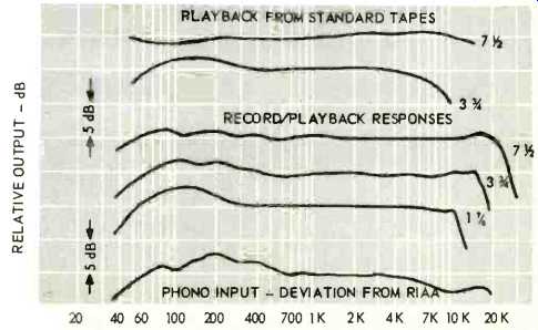
Fig. 3-Frequency response curves.
The input signals required for 0 recording level were measured as .02 mV at the microphone inputs, 4.0 mV at the line inputs, and 1 mV at the magnetic phono input. The same recording level gave a line output of 0.95 V. Channel separation was identical with the hum and-noise measurement. Fast-forward and rewind time measurements for 1800 feet of tape-Scotch 203 was used for all measurements, since the machine was labeled to indicate that low-noise tape should be used-was a mere 120 seconds, somewhat better than specifications.
Since our test tapes were only extended to 20,000 Hz, we went further at 7 1/2 ips and made extended measurements up to 30 kHz. Response was down 4 dB at 23 kHz, down 11 dB at 26 kHz, and down 16 dB at 28 kHz, which indicates that the crossfield technique works well. The playback head gap is claimed to be 80 micro-inches (2 microns ), which usually ensures excellent high-frequency response.
Without a doubt, this is the top of the line in the Tandberg tradition. This observer has always deplored the use of "magic-eye" tubes as level indicators, although we realize a good case can be made for them over meters, but. we just happen to have been trained to use meters and we are familiar with their idiosyncrasies and their limitations-so we were pleased when Tandberg switched to meters. We were also pleased when Tandberg added the "free" position to the familiar "T" slot of the tape-motion lever. Now with the addition of the solenoid and the START/STOP button, the 6000 series is apparently the best of the always reliable Tandberg line. Mechanically it is neat, with plenty of room within the case so that it is readily accessible and easy to get at for any servicing that might be necessary.
--C. G. McP.
(Audio magazine, Jul. 1970)
Also see:
Tandberg Model TD 20A Open-Reel Tape Deck (Equip. Profile, Mar. 1979)
Tandberg TCD 3014 Cassette Deck (Sept. 1984)
Studer-ReVox Model B77 Open-Reel Tape Recorder (Sept. 1978)
OPEN-REEL vs. CASSETTE (April 1977)
Logic Control of Tape Recorders (Apr. 1973)
= = = =