(Note: This article is Part II in a multi-part series, but works fine as a stand-alone article. We will soon publish the other articles. Part 1 is here.).
Turntables and Noise
In my first article (coming soon) I discussed the various types of noise one might encounter in a phono playback system, and particularly the fact that the pickup sees mechanical motion and converts it into an electrical signal. Unfortunately, the pickup cannot discriminate one mechanical motion from another, and therefore if an extraneous mechanical motion is added to the signal on the record, a distorted playback will result. The two general classifications of extraneous noise are those resulting from poor turntable design and those created by external sources, the latter problem being feedback. The first article ended by describing a mechanical-energy decoupler, consisting of a series of springs and a special dense board, designed to isolate the turntable from both mechanical and acoustical environmental energy. The description of this energy decoupler was simplified considerably for purposes of illustration. It was shown that a vertical spring action was effective for decoupling mechanical energy to the turntable, and this is true to a degree.
However, the problem of completely decoupling the turntable from environmental energy is considerably more complex. Environmental energy does not reach the turntable in only the vertical direction. It arrives at the turntable from several major directions and an almost infinite number of integrated directions. A damping unit must therefore be capable of isolating the turntable environmental energy arriving from all directions.
The mechanical energy caused by poor turntable design is yet another story. It cannot be controlled by the user, yet it is important that he be aware of it when making his initial purchase.
As we discussed earlier, a turntable's design may be classified into several basic sections: 1, the drive system (motor); 2, the transmission system (motor-to-turntable coupling); 3, the platter and/or flywheel system, and 4, the main chassis.
The drive system in early turntables generally consisted of a motor shock mounted to the main chassis by means of rubber supports, a turntable platter, and a rubber idler. When the turntable was switched off, the rubber idler wheel was automatically disengaged from contact with the motor shaft and the turntable platter. When the turntable was switched on, the rubber idler wheel would swing into its operating position and the mechanical operation was as follows-the rotating motor shaft contacted the rubber idler wheel, which in turn rotated against the inner rim of the turntable platter which rotated.
There were two methods used to keep the rubber idler in contact with the motor shaft and platter. One method was to use a spring-loaded lever to hold the idler in position, and the other was to use the rotational direction of the motor shaft to actually jam the idler into its operating position. Needless to say, both approaches are inadequate for a state-of-the-art design. If we examine this basic design approach, it becomes immediately obvious that the high-stress contact between the motor shaft and the idler wheel forces the motor shaft to rotate eccentrically in its upper bearing, with a counter rotating action in its lower bearing. This motor shaft and bearing action is intolerable since it creates high-stress mechanical vibrations easily within the audible range. The rubber idler wheel, being compressed against the inner rim of the turntable, forces the turntable platter shaft to rotate off center in its upper bearing contact and, at the same time, counter rotating in its lower bearing area. This creates a second mechanical vibration condition within the turntable system. The rubber idler wheel, being compressed between the motor shaft and the inner rim of the turntable platter, has now become distorted in shape and produces multi-directional rippling motions intermittently in and out of mechanical phase with the motions of the motor shaft and the turntable platter. This is a third mechanical vibration, and when you add these three mechanical vibrations together, you can see how monstrous the situation is beginning to get. But wait a minute, I'm not finished yet! As was mentioned, the idler wheel's operating position is maintained by either a spring-tension device or by the rotational operating pressures of the motor shaft driving force and the resistive force of the inner rim of the turntable platter. If the spring -tension system is used, you may add spring oscillation to the list of problems. If you use the system of rotational contact, considerable force is applied to the rubber idler, thereby increasing the mechanical vibration level. This general system is still being used today. In all fairness, however, I must add that it has been refined to a reasonably acceptable performance level.
Tonearm Vibration
Now that we've seen where mechanical vibrations occur within the turntable itself, let us also examine their influence upon the tonearm. The direction the above mechanical vibrations follow to reach the tonearm and upset its function are as follows. The mechanical vibrations from the turntable platter and shaft are transmitted to the record, added to the recorded signal and picked up directly by the phono stylus. The other mechanical vibrations are transmitted from the drive mechanism to the turntable chassis, then to the rear tonearm support, continuing up into the tonearm tube itself, and finally into the phono pickup. It can be easily seen that this second vibration reaches the phono pickup much later than the first, creating phase, delay, and decay problems in the recorded signal.
(Please keep in mind that I am only glossing over highlights of turntable problems. To do a complete analysis of turntable design would be a very complex affair and could not be completed even in several articles like this.) The two remaining turntable designs are the belt drive and the center motor or direct drive. Since the belt drive is next in the evolutionary cycle, I will discuss it first.
A belt-drive turntable is just that, a turntable driven by the motor via a flexible belt. The belt is simply used in place of the rubber idler wheel. Figures 5, 6, and 7, show three variations of the belt-drive system. In Fig. 5, you see the basic belt drive, a motor with its shaft positioned outside the turntable perimeter and a flexible belt stretched around the outer diameters of the motor shaft and the turntable platter. Figure 6 shows the double motor drive system in which a motor is positioned on each side of the turntable platter with a single belt stretched around the two motors and the turntable. In the first belt-drive system the belt tension is between the motor shaft and the platter. This belt tension causes both the motor shaft and the turntable shaft to be pulled toward each other, resulting in an erratic shaft and bearing action identical to that which I described in the idler wheel system. In the double-motor belt-drive system, the belt pressures on the platter are equalized, however, we now have two motor shafts being pulled together by belt tensions. This of course results in an erratic motion between the motor shafts and their respective bearings.
The third example of the belt-drive system has two belts and an intermediate idler wheel pulley. The motor shaft drives the pulley by means of the first belt, and the pulley drives the turntable by means of the second belt. The theory of the belt drive is that it will drive the turntable and at the same time absorb mechanical vibrations from the motor. The big drawback here is that the filtering of the belt is accomplished through its flexibility, and this very same flexibility creates its performance limitations. When the belt system was first introduced, a belt that was highly flexible, had a minimum of longitudinal stretch, and had long term elastomeric stability simply did not exist. At the present time, the technology of flexible belt design and manufacture has become highly sophisticated, and the net result is that a good belt drive system may easily compete with the best direct -drive systems.
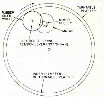
Fig. 1-Drive system of early turntables.
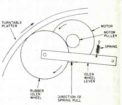
Fig. 2-This drive system uses a spring-loaded lever to keep the idler wheel
in contact with the motor pulley and the platter rim.
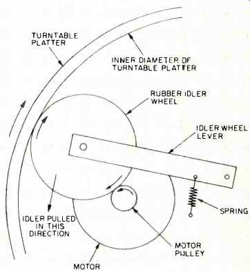
Fig. 3-This variation of the lever system jams the idler wheel between the
motor pulley and the platter rim.
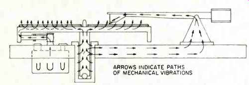
Fig. 4-The arrows indicate the paths that mechanical vibrations take to reach
the tonearm and cartridge.
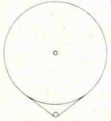
Fig. 5-Single-motor belt-drive system.
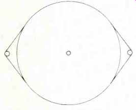
Fig. 6-Dual-motor belt -drive system.
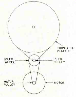
Fig. 7-Belt-drive system using an intermediate idler.
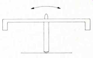
Fig. 9-Basic "teeter-totter" motion of platter and spindle.
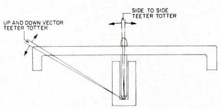
Fig. 10-The amount of "teeter-totter" motion is the product of the
side-to-side motion of the spindle times the ratio of spindle length to platter
radius.
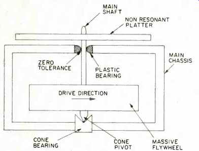
Fig. 11-One attempt to beat drive system problems.
Direct Drive Systems
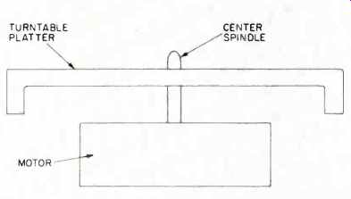
The last system to be discussed is the center motor or direct drive. In the direct-drive system, both the belt and the rubber idler wheel are eliminated, and the turntable platter is mounted directly onto the motor shaft. One could assume that this would be the ideal system, but, alas, it too has problems. Since we have now mounted the platter directly to the motor shaft, we no longer have either the belt or the idler wheel to filter motor vibrations. In the center -drive system, every mechanical inaccuracy and vibration of the motor is directly transmitted to the turntable platter! Fortunately, the motors designed for the direct-drive system are superbly built, but there are some electronic control problems of a minor nature which are being corrected at a very fast rate. There are already digital controls which are beginning to approach quartz crystal control accuracy and yet still afford the ease of manual speed variation. There is very little doubt that future turntable design will continue in the direction of the direct -drive system, considering the potential sophistication it is capable of providing.
Although the turntable drive systems are improving at a fairly rapid rate, one problem basic to all turntables still exists--I call it the teeter-totter of the turntable platter. Figure 9 shows a conventional platter and shaft standing on the end of the shaft. It is obvious that the weight of the platter will cause the platter to topple over if it were to stand by itself. When the platter is in the turntable bearing assembly, it tries to do the very same thing--it tilts. The result is that one side of the platter shaft contacts the upper bearing and the opposite side of the shaft contacts the lower bearing. When the shaft rotates, then, it does not rotate on axis. The weight of the platter high above the shaft and bearings creates a sideward thrust and a counter rotating of the platter shaft in its bearing assembly. This counter rotation of the shaft causes a vibratory action in the shaft which is transmitted directly to the turntable platter and then to the phono pickup. The above condition exists in all conventional turntables, regardless of the drive system employed.
It can be seen in Fig. 10, that if the turntable radius is six inches and the bearing length is three inches, a two to -one ratio exists between the shaft and bearing clearance and the platter teeter-totter. The additional vertical signal generated by the pickup due to the, vertical teeter-totter is added to the recorded signal as distortion! This condition exists in all turntables regardless of the drive system employed in them.
Many years ago, in an effort to combat these problems, I designed a turntable which had a massive flywheel mounted in the lowest possible position on the shaft (Fig. 11) and a very light platter on the top of the shaft.
The upper platter was made of a non resonant material and was used to carry the record. The shaft was as long as the turntable radius, the lower support bearing was a cone type, and the shaft made a single point contact with the cone bearing. The upper bearing was a sleeve bearing of self-lubricating plastic. The elastomeric qualities of the plastic allowed a zero tolerance between the shaft and the bearing. The shaft and bearing friction was so low that the eight pounds of flywheel could be driven beautifully by two tiny clock motors. The stylus force could be increased to 50 grams without slowing the turntable. Needless to say, the flutter and wow were extremely low, but more important the rumble figure was better than -85 dB.
Granite-Epoxy Platters
In my first article I discussed the problem of acoustic feedback in turntable platters. This, as I said, is caused by acoustic energy creating mechanical energy in the platter itself, much the same as wind in a church bell causes it to hum or resonate. The only way to overcome this condition is to damp the platter or to make the platter of a dense, non-resonant material.
I, for one, would like to see platters made of the granite-epoxy presently being used for turntable chassis. A turntable platter of this material would make an excellent flywheel and be dense and massive enough to effectively mass damp mechanical vibrations from either design or environmental sources.
The turntable chassis should also be as massive and as dense as possible since it must perform two important functions, mass-damp acoustical energy coming to the turntable from room sources and mass-damp mechanical energy created by the turntable drive system before it can reach the tonearm base.
As we have seen, turntables and their extraneous mechanical vibrations may affect a change in the sound of a phono pickup, but the turntable itself does not "sound." In my next article, I will discuss tonearm design and how the tonearm manages to affect the sound of pickups.
Also see:
Turntables (Part 1) (July 1977)
Turntables (Part IV): Arm/Cartridge Resonance (Oct. 1977)
Dynamic Range Requirements of Phonographic Preamplifiers [Tomlinson Holman, July 1977]
(Source: Audio magazine, July 1977)
= = = =
