MANUFACTURER'S SPECIFICATIONS
FM TUNER SECTION. IHF Sensitivity: 2.0 µV. S/N Ratio: 65 db. Capture Ratio: 2.5 dB. Selectivity: 46 dB. Image Rejection: 60 dB. I.F. Rejection: 70 dB. Spurious Response Rejection: 80 dB. AM Suppression: 40 dB. THD: Mono, 0.5%; Stereo, 0.8%. Stereo Separation: 1 kHz, 35 dB; 10 kHz, 25 dB. 19 kHz and 38 kHz suppression: 55 dB.
AM TUNER SECTION. Usable Sensitivity (internal antenna): 300 µV/Meter. S/N Ratio: 50 dB. Image Rejection: Greater than 50 dB. I.F. Rejection: Greater than 40 dB. Selectivity: Greater than 30 dB. Harmonic Distortion (at 80% modulation) 1.0%.
AMPLIFIER SECTION. Power Output: 30 watts per channel, 8 ohm loads, both channels operating. Rated THD: 1 .0%. Rated IM: 1.0%. Power Bandwidth: 15-30,000 Hz. Frequency Response: 15-22,500 Hz. Damping Factor: Greater than 20. Stability: Unconditional. Hum and Noise Below Rated Output: Phono, -63 dB; Aux, -70 dB; Tape Monitor, -70 dB. Sensitivity for Rated Output: Phono, 3.5 mV; Aux, 500 mV; Tape Monitor, 500 mV.
GENERAL SPECIFICATIONS. Power Requirements: 120 V 50/60 Hz, 180 watts maximum. Dimensions: (including knobs and extended antenna) 18 in. W. x 5 1/4 in. H. x 18 1/8 in: D. (11 1/2 in. D. excluding knobs and extended antenna).
Weight: 22 1/2 lbs.
Retail Price (including walnut grain enclosure): $289.00.
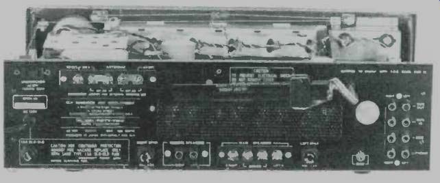
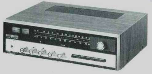
Fig. 1--Rear panel
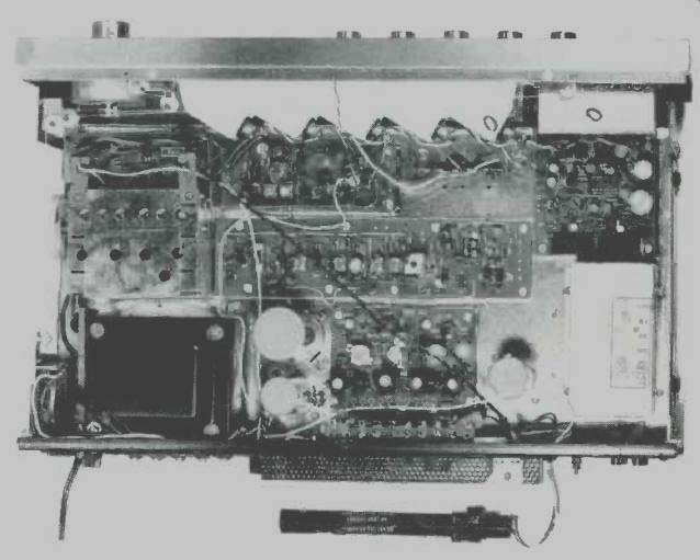
Fig. 2--Chassis from above.
The trend towards overlapping of product types continues amongst the component high-fidelity manufacturing fraternity.
Recently, we reviewed the first receiver product of a well known and respected tape-recorder manufacturer, and now KLH comes up with a receiver line to complement its famous loudspeaker system products. We had an opportunity to examine both the KLH 52 (reviewed here) and their lower powered Model 55 which resembles this higher powered receiver in outward appearance but contains several circuit differences other than just the lower power rating.
The Model Fifty-Two, pictured above, is equipped with a good looking gold and blacked-out panel, end-framed to produce a very massive-looking three-dimensional effect. The upper portion of the panel includes a pair of illuminated meters (signal strength and center-of-channel tuning), well calibrated FM and AM dial scales, a linearly calibrated logging scale, and a good-sized tuning knob coupled to an effective flywheel. Just below the dial scales are a series of program source designations which become illuminated when the particular program source is selected. The now indispensable "stereo indicator" light also forms part of this word grouping.
Along the gold colored lower portion of the panel are a stereophone jack, a four-position program source selector switch, dual concentric (clutch type) bass and treble controls for each channel, a balance control, and a master volume control which, in its farthest counterclockwise position, turns off power to the receiver. A row of seven push buttons are used for such secondary functions as LOUDNESS CONTOUR activation, MONO/STEREO MODE selection, TAPE MONITOR, FM interstation MUTING, HIGH FREQUENCY FILTER, and MAIN and REMOTE speaker selection. KLH engineers may just have saved some needless service calls by having the speaker switches operate just opposite to the way we've seen them on most other "push button" selectable speaker switch arrangements.
Instead of having to push either the MAIN or REMOTE speaker switches IN to hear sound, the normal out position of either switch connects the appropriate speakers. You have to push the buttons in to DISconnect speakers--a nice touch for non instruction-book readers (most of us) who might panic if they turned on the new receiver and heard nothing.
The logically laid out back panel is shown in Fig. 1. Included are antenna terminals for 300 ohm FM antenna inputs (a link must be swung away to disconnect the "built in" line cord coupled antenna) and a similar arrangement for connection of an outdoor AM antenna. Main speaker systems are connected to well separated screw terminals, while provision for remote speaker systems is made by phono-tip jack connectors. Tape out and in, phono input, and aux input jacks are all located at the right of the rear panel, and there are line fuse and individual left and right speaker fuses along the lower edge of the back panel. An unswitched a.c. convenience outlet plus the usual pivotable AM bar antenna complete the rear panel layout.
The photo in Fig. 2 is an overall view of the internal wiring and layout of the Model Fifty-Two Receiver. The shielded front-end uses a four-gang capacitor and features an FET in the r.f. stage. The i.f. module uses a total of five stages, with two IC limiters and a ceramic filter. The multiplex demodulator circuit employs a single integrated circuit, and there are internal adjustments for varying muting threshold and mono/ stereo threshold. The AM circuitry includes a two-i.f. system and also uses a ceramic filter. Preamplifier and voltage amplifier circuitry is fairly conventional, with an FET being used in the tone control circuitry. A quasi-complementary symmetry output circuit is used in the power amplifier section and includes short circuit protection in addition to the speaker fuses already noted.
Performance Measurements
Conservation in "spec writing" on the part of the KLH people became apparent as we began to measure this receiver. Almost every FM parameter turned out to be better than claimed. For example, as shown in Fig. 3, IHF sensitivity for our sample was measured as 1.6 µV. Before all the theoreticians send letters explaining that 1.6 µV of IHF sensitivity is "impossible" to achieve in the light of the natural laws of physics (the theoretical limit across 300 ohm input impedance has been calculated to be something just short of 1.7 µV for an S/N ratio of 30 dB), it must be noted that figures of 1.6 µV are attainable for IHF sensitivity, albeit at the expense of adequate bandwidth. In the case of the KLH receiver, this means that at 1.6 µV input, bandwidth is a bit restricted, but it quickly broadens out above a signal input level of 2.0 µV, which is all KLH claimed for the receiver in the first place.
Ultimate S/N measured 71 dB, well above the 65 dB claimed, and the 50 dB S/N point was reached with an input of only 2.4 µV. Mono THD reached a low figure of 0.36% (again, better than the 0.5% claimed) and even with signal inputs as low as about 20 µV, THD at 100% modulation was under 1.0%, as shown in the curves of Fig. 3.
Fig. 3--Monophonic FM performance characteristics.
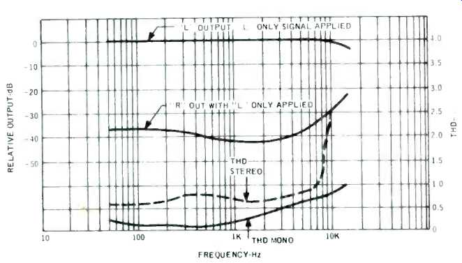
Fig. 4--FM stereo separation and THD performance characteristics versus frequency.
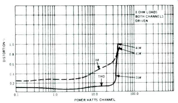
Fig. 5--Distortion characteristics at 1 kHz.
Stereo FM separation was also better than claimed, as shown in Fig. 4. Mid-band separation was just over 40 dB and remained greater than 35 dB all the way down to 50 Hz.
At 10 kHz, separation was exactly 30 dB, reducing to 25 dB at the end of the FM audio spectrum, at 15 kHz. A plot of THD versus frequency is also shown in Fig. 4 and, in the case of mono performance, total THD was under 1% even at 15 kHz, with considerably lower figures obtained for more significant mid-band and low frequencies. THD in stereo hovered around the published specification of 0.8% for most frequencies, rising to 2.5% at 10 kHz, largely as a result of "beat" frequencies rather than actual harmonic distortion. Other results obtained through actual measurement (but not displayed graphically) included capture ratio readings of 2.0 dB (against 2.5 dB claimed), selectivity of 53 dB (we would have been critical had the results been limited to only the 46 dB claimed), AM suppression of better than 50 dB, and spurious response rejection of well over the 80 dB claimed.
As received, the stereo/mono switching threshold was adjusted to about 4 microvolts and, in view of the S/N performance of the Fifty-Two, this seemed to be a perfect setting.
Not so with the muting threshold setting, however, since its action is not as instantaneous and complete as we have seen on some competitive products. Depending on when you want to call the mute circuit "defeated" by a signal, this setting ranged from 7 to 12 microvolts. A lower setting seems called for (say, 4 to 7 microvolts) in view of the excellent quieting characteristic discussed earlier. We feel, however, that the action of the mute circuit during transition from "off" to "on" could be more positive as its present range might result in marginal situations where the signal "partially" opens the circuit, resulting in varying audio level and varying distortion percentages. In the course of our listening tests, however, we did not run into that type of situation, since most of our signals received were well above the 12 microvolt level, as they would be in most situations.
Figure 5 is a plot of THD and IM versus power output per channel, and in both cases rated distortion was reached at power output levels considerably in excess of the 30 watts claimed. In fact, at 35 watts per channel output, THD measured only 0.35% while at rated output, THD was a mere 0.15%. If we were rating this receiver's power capability, we'd definitely call it 35 watts per channel, for 8 ohm loads, both channels driven.
Even at this 35 watt reference level, THD remains well below the rated 1.0% for all audio frequencies, as shown in the graphic plot of Fig. 6. At nominal 1 watt levels, THD is essentially down to the distortion levels of our signal generator--well below 0.1%-for all frequencies of interest.
Power bandwidth, plotted in Fig. 7, extends from 12 Hz to 35 kHz. It should be pointed out that we have arbitrarily assumed a "0 dB" reference of 35 watts per channel, rather than 30 watts, as claimed by the manufacturer, and still the power bandwidth exceeds the end points specified by KLH. Figure 8 discloses the range of some of the controls of the KLH Model Fifty-Two. Loudness-contour action for the-30 dB (from maximum volume) setting was a bit excessive, but then the whole question of loudness settings is rather arbitrary since proper Fletcher-Munson compensation depends more upon program source and speaker efficiency than it does on the components selected for use with the loudness control.
The high frequency filter has a 6 dB per octave slope, but its turnover point is optimally located at about 3500 Hz, making it somewhat more effective as a filter than the treble control might be.
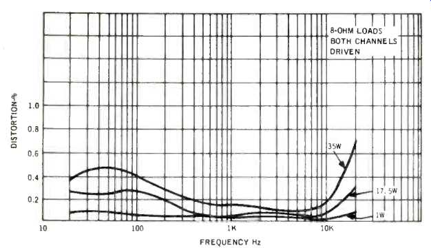
Fig. 6--Distortion versus frequency at various power levels.
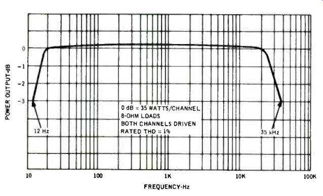
Fig. 7--Power bandwidth.
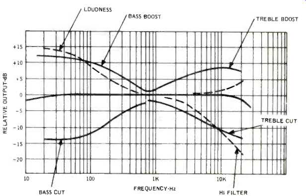
Fig. 8--Tone, filter, and loudness (-30 dB) characteristics.
Listening Tests
The KLH Model Fifty-Two certainly sounds and behaves more like a higher powered receiver than its "specs" would indicate. We had no trouble driving some of the low-efficiency book-shelf systems manufactured by the very same KLH (how embarassing, otherwise!). FM calibration was excellent, and there was no evidence of drift.
During the measurement phase of our tests, we had noted that while the zero-center meter was "right on" the zero mark for minimum distortion tuning, it did not quite correspond to "maximum stereo separation" in stereo FM. Few listeners realize that propercenter-of-channel tuning is as vital for stereo FM separation as it is for lowest distortion. Despite this slight discrepancy (which we feel sure could be "aligned out" of the receiver), there was plenty of audible separation even if we simply tuned for meter center.
While the KLH Model Fifty-Two does not offer some of the frills of more expensive receivers (low filter, multiple phono inputs, etc.) it does present very honest performance and is well worth its "just under $300" price. All other specs noted by the manufacturer and not specifically mentioned in this report were met or exceeded, with the exception of phono input sensitivity, which we measured at 6 mV instead of the 3.5 mV claimed. It is possible that KLH might be measuring this figure at 400 Hz (part way up the bass equalization curve), whereas we measure this parameter at 1000 Hz, and that could account for the difference. Some of the lower output magnetic cartridges may, therefore, not be able to push the amplifier to rated output when playing dynamically restricted discs and we would have liked to see a bit more gain in the preamp circuitry. Volume control tracking was excellent all the way down to -60 dB from maximum setting, and hum and noise were all but inaudible at the listening levels we used.
A special word should be added about the owner's instruction manual which KLH packs along with each unit. Aside from giving a complete description of controls and specifications, the manual covers a good many items ordinarily found only in complete books about hi-fi installations. These include selection, stripping, and tinning of speaker wires, a discussion of the merits of indoor and outdoor antennae, care of records, and connection of electrostatic headphones. While some of the other topics are regularly covered in manufacturer's instruction manuals, KLH is to be congratulated for treating them in greater than usual depth.
-Leonard Feldman
(Audio magazine, Aug. 1973)
Also see:
KLH Model 33 Loudspeaker System (Dec. 1970)
JVC S-300 FM Stereo/AM Receiver (Sept. 1976)
= = = =