Author: Roy F. Allison [President, Allison Acoustics, Inc. Natick, Mass. 01760, USA]
The work of Thiele' and Small in recent years has changed the procedure by which loudspeaker systems are designed. They did not extend the inherent limits of performance of low frequency loudspeakers, but they did define those limits. They quantified the interrelationships among cabinet size, system efficiency, and low-frequency response range, and they developed systematic synthesis techniques which enormously simplified design procedure.
It is certainly true that this has resulted in an improvement in the average quality of loudspeaker systems, because it is now easier for manufacturers to optimize their designs.
Indeed, several manufacturers emphasize in advertisements that their products have been designed by computers programmed with the Thiele/Small synthesis formulas.
Unfortunately, consumers can enjoy the benefits of this improvement only to a very limited degree. It is traditional to design loudspeakers for flat frequency response in an anechoic test chamber. The Thiele/Small design formulas assume that kind of reflection-free environment. But people do not use loudspeakers in anechoic chambers; they use them in domestic living rooms. Normal rooms react on loudspeakers in the bass range, and this can change their power output significantly.
We can understand why this is so if we look at the formula for reference sound pressure from a loudspeaker at low frequencies.
This is derived by Beranek [1] as follows:
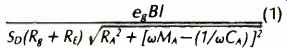
(1)
where |Uc| = volume velocity of diaphragm; eg= open-circuit amplifier voltage; B= magnetic flux density in air gap; l = length of voice-coil wire in air gap; So = area of the diaphragm; Rg= output impedance (resistive component) of the amplifier; RE= voice coil wire resistance; RA = sum of electrical, mechanical, and acoustic resistive elements; ω = 2 pi f radian frequency; MA = sum of the acoustic masses, including diaphragm and voice coil, and CA= total acoustic compliance of suspension and box. All elements are transformed to acoustic impedances and expressed in mks units.
Above the resonance frequency but within the piston band, and on the reasonable assumption that RA2 is small relative to w2MA2 (1) can be simplified to
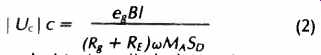
and this is called the reference volume velocity.
Also, a loudspeaker system in this frequency region is a small source, that is, its radiation is essentially omnidirectional. For such a source the sound pressure is related to the volume velocity by
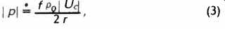
(3)
where |p|c= sound pressure at a distance r from the loudspeaker, f= frequency in Hertz, and pc, = density of air. If we combine (2) and (3), we obtain the formula for reference sound pressure:
Most of the terms in this formula do not change with the loudspeaker system's environment, but two of them do change. One is the numerical factor, 4n, in the denominator. This denotes the solid angle (the three-dimensional space) into which the woofer radiates sound energy. The solid angle is measured in steradians; 4n steradians represents full space, which is the radiation angle that would be seen by the woofer if the system were suspended in mid-air high above the ground. Because low-frequency sound is radiated omni-directionally, the woofer in such an environment would propagate sound equally in all directions and the sound energy would continue outward without encountering any nearby reflecting boundaries.
An anechoic chamber simulates such an environment.
Now if the loudspeaker system were to be mounted in the middle of a very large wall, so that the woofer diaphragm were flush with the surface of this boundary, the radiation angle would be halved. The woofer would be operating in a half-space environment, a solid angle of 2pi steradians.
The radiation formula tells us that the reference sound pressure will be doubled, and experiment shows this to be true. We do find a 6-dB increase. An increase of 3 dB is obtained because we have confined all the radiated power to half the space it occupied before. This 3 dB is of no importance because it involves no change in power output. But a second increase of 3 dB is the result of an actual doubling of power radiated by the woofer. It is twice as efficient in 2pi space as it is in 4n space.
Let us further suppose that we are able to position the woofer at the intersection of two mutually perpendicular walls. Again the radiation angle is halved, this time to pi steradians; again the power output of the woofer is doubled.
Still another reduction in radiation angle, to pi/2 steradians, is often found in real living rooms when a loudspeaker system is placed in a corner with the woofer close to the floor. Its power output is increased another 3 dB at low frequencies, for a total increase of 9 dB above the power radiated into full space.
It should be emphasized that these theoretical increases in radiated power with decreasing radiation angle are obtained only when the driver is close to the boundaries. In an acoustical sense, drivers are never "close" to room surfaces at frequencies above 500 Hz or so. Therefore, real rooms by changing a loudspeaker system's power output in one frequency region only, in an amount determined by where the user places the cabinet in the room completely alter the original balance of the system as it was in the anechoic chamber. And because such room effects cannot be avoided, it follows that loudspeaker systems designed for flat response in. anechoic chambers cannot produce a flat power response in real rooms.
We have said that a driver must be close to a room boundary in order to be affected by it. A discussion of what "close" means brings us to the other term in our formula which changes when the loudspeaker system is brought out of the anechoic chamber and into the listening room. That term is' p0, the air density.
Of course, the average density varies only in accordance with changes in barometric pressure. But instantaneous density is proportional to instantaneous pressure, and sound itself is the result of variations in air pressure which occur at an audible rate. In the anechoic chamber, a loudspeaker driver creates audio-frequency changes in pressure which travel to the chamber walls and are absorbed there. In a living room, conversely., sound energy reaching the walls is reflected back to the driver where it either adds to or subtracts from the instantaneous pressure on the driver diaphragm, depending on the phase relationships. If a boundary is "close," the reflected pressure is strong enough to change the instantaneous pressure at the diaphragm surface significantly and to increase or decrease the acoustic power radiated.
Closeness of a driver to a boundary is. dependent not on the absolute distance between them, but upon the distance in units of wave length.
Therefore, a driver may be acoustically close to a boundary at low frequencies, for which sound waves are long, and not close at higher frequencies which have shorter wave lengths.
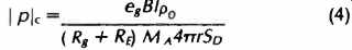
This relationship is quantified in Figs. 1 through 3. The power output of a direct-radiator driver in its nondirective frequency range is shown (relative to its output in an anechoic chamber)
when it is put near a single boundary (Fig. 1); when it is equidistant from two boundaries intersecting at a right angle (Fig. 2), and when it is equidistant from three mutually perpendicular boundaries (Fig. 3). In each case the horizontal scale is in fractional parts of a wave length.
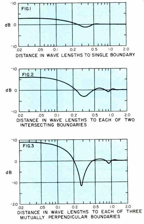
Figs. 1-3 Power output of small acoustic source close to one, two, and
three boundaries relative to power output in 4 pi space.
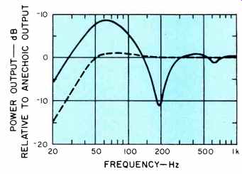
Fig. 4 Output of a typical high-quality loudspeaker system in anechoic
test chamber (dashed line), and power output of same system with woofer
50 cm from three mutually perpendicular room surfaces ( solid line).
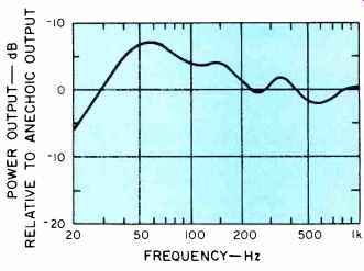
Fig. 5 Power output of same system as Fig. 4, but with woofer located
20 cm above floor, 51 cm from one wall, and 122 cm from other nearest wall.
We can learn much from a careful examination of these curves. For example, it is obvious that the augmentations of power output predicted for reductions in radiation angle (+3, +6, and +9 dB for 2n, Tr, and pi /2 steradians, respectively) are obtained only when the woofer is placed a small fraction of a wave length from the boundaries. At a distance of 1/10 wave length, the three-boundary augmentation has already decreased from 9 dB to 7 dB. A typical distance of the woofer from the three nearest walls in a real living room might be 50 cm, and 50 cm is 1/10 wave length at 69 Hz. At higher frequencies, the augmentation decreases rapidly, because 50 cm becomes a larger fraction of a wave length as frequency increases.
Eventually, as we continue to increase the frequency of the sound signal, the reflected pressure from the nearby walls no longer arrives back at the woofer diaphragm in phase with the driving signal, and at that frequency or above it the driver is no more efficient than it is in full 4 pi steradian space. This limiting frequency is that for which the distance to the walls is 1/4 to 1/5 wave length, depending on the number of boundaries involved. In our hypothetical example, with a woofer located 50 cm from each surface in a three-boundary intersection, that frequency is approximately 140 Hz.
At still higher frequencies (200 Hz in our example) the woofer is about 3/10 wave length from the walls. Then the reflected pressure is in opposite phase with the motion of the diaphragm. As the woofer attempts to create a compression, the reflections cause a rarefaction, and vice versa. The woofer believes that it is working in a partial vacuum; its power output is correspondingly reduced. But the amount of power reduction is not in neat alignment with the number of reflecting boundaries. As Fig. 1 shows, an out-of phase reflection from one boundary has a minimal effect, with only 1-dB reduction at the worst frequency.
Equidistant reflections from two boundaries are considerably more effective, causing a 3-dB drop below full-space output in the critical frequency band. But reflections from three equidistant boundaries cause a deep reduction, more than 11 dB, below reference level. The total variation (including the 9-dB boost at very low frequencies) is about 20 dB from a speaker system that measured flat in an anechoic chamber! Figure 4 shows the power output vs. frequency for such a system, assuming a system resonance frequency of 50 Hz with a Q of 1 and 50-cm distance to each of three room surfaces.
The curves also show that, beyond 5/10 wave length distance, the boundaries have insignificant effect on loudspeaker performance. In our example, a 50-cm distance is 5/10 wave length at 345 Hz.
Figures 1 through 3 make it apparent that the effect of multiple out-of phase reflections is more than simply additive. It follows that one should attempt to place the woofer of a conventional speaker system so that its distances to nearby room surfaces are as different as possible, and thereby place the out-of-phase reflections at widely different frequencies. When this can be done, it is very helpful in smoothing the system's low-frequency output. Power output vs. frequency is shown in Fig. 5 for our reference system when the woofer is placed 20 cm above the floor, 51 cm from one wall, and 122 cm from the other nearest wall.
Another way to deal with the effects of room boundaries is to place the woofer far away from them all. If there is at least 1.25 meters from the woofer to the nearest room boundary, all the major effects of the boundaries will occur well below 100 Hz, where they will be less audible than they are normally. Of course, this would not be convenient in most living rooms.
Both of these stratagems are defensive maneuvers. They limit the damage but do not prevent it entirely. A frontal attack is preferable in this case. It consists of designing loudspeaker systems to work in conjunction with the room boundaries, taking full advantage of their ability to increase efficiency at low frequencies and also avoiding the out-of-phase reflection problem altogether. These are several ways in which this plan can be implemented, but all have these steps in common:
1. Decide whether the system is to be used in .proximity with one, two, or three mutually perpendicular room surfaces. The balance must be set differently for each kind of system because, as we have seen, the woofer's efficiency changes with its radiation angle.
2. Design the cabinet to locate the woofer ( or woofers) as close as possible to the room surfaces.
3. Set the crossover frequency so that the operating range of the woofer is limited to well below the "notch" frequency. Then the reflected pressure will always be in phase with, and will reinforce, the direct output of the woofer. The woofer's power output can then be flat. Note that in practice this requires a three-way or four-way loudspeaker system, because even with placement of the woofers very close to the boundaries a low crossover frequency (400 Hz or lower) must be used.
4. Finally, locate the mid-range driver in the cabinet far enough away from the boundary intersection so that it is at least one-half wave length distant at the crossover frequency and above.
Then the output of the mid-range driver (and of the tweeter) can be made flat and unaffected by the room surfaces.
Some loudspeaker systems designed in accordance with these principles are now available. I feel certain that others will soon follow.
Reference
1. L. L. Beranek, Acoustics (McGraw-Hill, New York, 1954), chapter 8.
(Source: Audio magazine, Aug. 1979)
Also see: The Importance of Speaker Directivity (Sept 1979)
= = = =