MANUFACTURER'S SPECIFICATIONS
Tonearm
Effective Mass: 9 grams.
Effective Arm Friction: Better than 0.02 grams.
Offset Angle: 27°. Tracking Angle Error. 1 degree, 40 minutes maximum deviation.
Stylus Overhang: 0.625 in. (16 mm).
Stylus Force Variation: From 1/4 gm to 3 grams.
Overall Height: 3 in. (76 mm) max.
Height Adjustment: 1% to 2% inches.
Weight: 7.75 oz. (220 gm).
Price: $149.50.
Phono Cartridge
Frequency Response: 20 Hz to 20 kHz.
Output: 5 mV/5 cm/sec.
Stylus Radius: 0.0006 x 0.0003 inches.
Nominal Vertical Tracking Angle: 15°. Compliance: Lateral, 15x10^-6 cm/dyne; Vertical, 7x10^-6 cm/dyne.
Inductance: 560 mH per channel.
D.C. Resistance: 2200 ohms per channel.
Tip Mass: Less than 1 mg.
Price: $174.50.
= = = = = = =
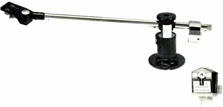
Decca has been making stereo cartridges since the beginning of the stereo era, about 20 years. The Decca MkVIe GOLD stereo cartridge is the latest version of a basic design which has undergone a continuous evolution since the late 1950s when I first made its acquaintance. At that time, shortly after the introduction of the modern stereo disc, the London/Scott ffss matched stereophonic arm and cartridge was advertised in Audio, on page 61 of the January, 1959, issue as being "... in a class apart from all the others ...." This quote was taken by Scott from a review that appeared on p. 48 of the Sept. 27, 1958, issue of Saturday Review magazine. The tip mass was stated as being 1 mg, which was very low for those days, and the ad mentioned the ill effects of tonearm mass/ cartridge compliance resonance effects at some low frequency. At that time, the Decca cartridge-arm attachment method required that the Decca cartridge be used only with the Decca arm. Since then, an adapter, which allows the Decca cartridge to be slipped on and off the arm very easily, has been developed, so the Decca cartridge may be used with other arms. More on this later.
I remember my first impression of the early London/Scott arm-cartridge combination was more than favorable. It had an uncanny ability to bring out inner detail in the early stereo discs and was very revealing. The idea of spending $58.00 for an integrated arm and cartridge (which precluded using cartridges other than the Decca) must have then seemed a disadvantage to some, but it allowed Decca to design for maximum compatibility of the arm-cartridge combination. (In the same issue of Audio, for price reference, a GE GC-5 stereo cartridge and a GE universal tonearm were advertised for $26.95 and $29.95 respectively.) It would seem hat to this day, the advantages of an integrated arm-cartridge design are traded for flexibility by most buyers. This flexibility probably allows more average or even poor arm cartridge combinations than it does truly excellent ones. The manufacturers know this but they must respond to demand or flexibility and caution the buyer as to the pitfalls as best they can.
In the case of the present review, both arm and cartridge are made by Decca, but some few tradeoffs in absolute compatibility had to be made to enable other cartridges to be used with the Decca arm. One tradeoff was the increase in effective mass due to the extra mass of the interchangeable headshell arrangement. This is true of all so-called "universal" tonearms which utilize plug-in headshell arrangements.
The extra mass of the coupling hardware is usually out at the pickup end of the arm, which is the worst place to add mass.
The quote mentioned previously was true in one sense.
The Decca cartridge is in an engineering design class by itself.
I am not aware of any other available cartridge which uses the same arrangement of coils or stylus assembly. The arrangement is essentially a vertical-lateral scheme which is electrically matrixed to extract the 45°-45° groove-wall modulations of the modern stereo disc. It derives from the early days of disc cutting. Some disc cutter heads allowed either lateral or vertical discs to be cut. Commercial monophonic phonograph records were lateral-cut discs in which the groove modulations were from side to side. Some radio transcriptions were cut with vertical modulations of the groove, as were the original Edison cylinders.
Some of the first modern stereo discs were cut using a lateral-vertical cutter head; one channel was lateral and the other was vertical. Since effects such as warp, rumble noise, etc. were dissimilar in each channel, it was decided to matrix the signal so that the same effects would be balanced between the channels. This also made the 45°-45° stereo record compatible with mono records since lateral modulation (mono signal) appears equally in both channels, making the source appear to come from the center between two speakers when the listener is positioned between the speakers.
(Movement toward the left or right by the listener will cause the apparent source of the sound to come from the nearest speakers due to the Haas or "precedence" effect, since there is no time difference in a mono signal.) Since phono cartridge designs such as the Western Electric and Decca were available, which had coil configurations allowing either laterally or vertically cut discs to be played, it was natural that a matrix scheme for 45°-45° stereo disc playback would be designed. Such a design is still with us in the Decca MkVIe.
The stylus cantilever system of the Decca cartridge is also different than that used in most other cartridge designs.
Rather than being supported by a damping block near the center, the Decca armature is clamped at one end. Figure 1 shows the arrangement. Because the signal from the groove modulations are picked up near the stylus tip, and not at the other end of a cantilever, Decca has called their system "Positive Scanning." The mass of the Decca London cartridge has been reduced from its predecessors by a factor of over four, a considerable achievement. The susceptibility to hum and stray magnetic fields has also been reduced. The output has, at the same time, been increased by about 50 percent. A process called "super cooling" is used to temper the stylus cantilever to eliminate the stress relaxation problems associated with forming it to its final shape.
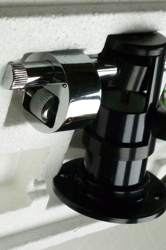
We feel that the relative ease or difficulty in achieving a satisfactory mounting of arm to turntable and cartridge to carrier is worthy of exposition. In order to be certain that some of the things encountered with the Decca arm were not just due to our single sample, we obtained a second unit for test and there were some differences between the first and second arms. While the mounting flange supplied with the first arm was metal, the flange supplied with the second arm was plastic. We tried to use the metal flange of the first arm with the second arm. There was additional play since the column of the second arm seems to be smaller. Also we discovered that the template supplied with the second arm called for 8 3/4 inches from the turntable center to the center of the arm-mounting hole. The mounting distance had been 8' inches on the template supplied with the first arm, yet the dimensions of both arms themselves are identical. The final pivot-to-stylus distance is set by sliding the cartridge in the headshell, and Decca supplies a template which is to be used to make this adjustment. After mounting the new plastic flange, we realized that the fit of the second flange and arm was too tight to allow easy adjustment of the arm height, so we shaved a small amount from the inside of the plastic flange. After doing this, the arm was mounted and could be adjusted, and there was no play between the arm column and flange after the two locking screws were set.
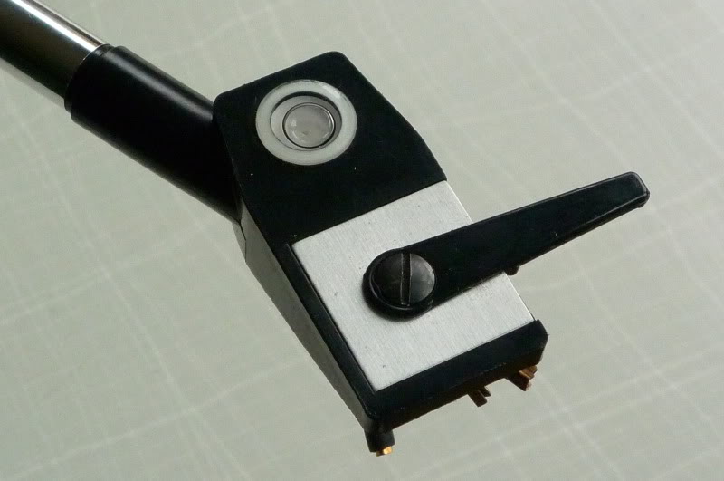
The template supplied to locate the arm-mounting hole is similar to those supplied by most tonearm manufacturers, requiring that the center of the mounting hole be projected down to the mounting surface. With high turntable platters, this distance can be a source of error, so a good amount of care should be taken to see that center of the projected mounting hole is directly below the hole in the template. An interesting trick is suggested by Decca for platter leveling prior to mounting the cartridge into the headshell. Since there is spirit or bubble level built into the headshell, Decca recommends that the headshell be placed on the edge of the turntable platter and the turntable then made level. After the cartridge is fitted, the headshell can no longer be used this way.
Mounting the Decca cartridge carrier to the Decca head shell, as shown in Fig. 2, is a bit more delicate than the more usual methods. The little spacers can be easily lost, and fumble-fingers are cautioned to take steps to avoid problems of this sort by spreading out a work cloth before beginning. The Decca cartridge slides into the carrier after the carrier has been fitted into the headshell; the Decca cartridge itself has no integral mounting holes. The headshell with cartridge is slipped into a socket on the end of the arm, and while there is no locking mechanism, the fit is tight. In fact, "slipped" is probably not quite a strong enough word to describe the effort required. The Decca cartridge has only three terminals since it uses a common ground terminal; we chose to solder both ground returns to the single ground pin of the cartridge carrier. The clearance between the cartridge and the record is very small so adjustment of the arm height should be checked carefully. Make certain that all the screws are secure and, after adjusting the tracking force with the counterweight, adjust the tilt with the lateral weight adjustment provided.
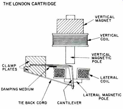
Fig. 1 Layout of the coils and magnets for the Decca London phono cartridge.
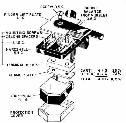
Fig. 2 Exploded view of the cartridge/headshell mounting and weights.
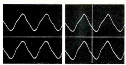
Fig. 3 Tracking on the CBS STR-112 test record, Band 9,+18 dB re: 11.2 pM
at 300 Hz. A) Tracking force at 0.7 gm, and B) at 1.5 gm.
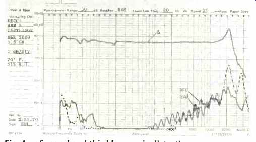
Fig. 4 Second and third harmonic distortion vs.
output in the left channel. Note: Some of the high frequency distortion is due to the B&K 2009 test record.
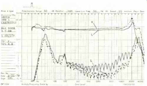
Fig. 5 Interchannel output vs. frequency with the B&K 2009 test record.
Notches in crosstalk are due to filter switching. Note increases in crosstalk
at 160 and 200 Hz.
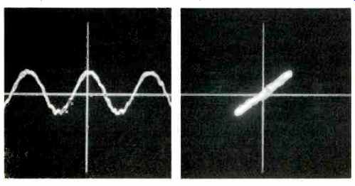
Fig. 6A Amplitude vs. time on both channels of the B&K 2009 test record,
Band 3. Sweep of 20 Hz to 20 kHz, with stop action at 3 kHz. Fig. 6B-X-Y
display of right vs. left channel for the same signals as shown in Fig. 6A.
Identical channels would make a straight 45° line.
Check to see that there are no rattles or excess play in the arm cartridge system. At this point, we recommend that the viscous fluid be applied to the arm pivot. It will take about 24 hours for the fluid to properly fill the cup around the pivot.
The Decca London arm was mounted to a Pioneer PLC-590 turntable using a 4N-in. square mounting block of 3/4-in. thick particle board which fits neatly and securely into the PLC-590 platform. The arm rest can be mounted by drilling a single hole on most turntables, but in the case of the PLC-590 the area in which the arm rest would be mounted contains the electronic controls.
The Decca London cartridge and headshell plus fittings weigh a total of 14.8 grams, with over 70 percent of this mass at the end of the tonearm going into the shell and fittings.
The cartridge itself weighs 4.1 grams; the headshell 5.4 grams; the plastic holder, threaded bar, screws, and washers 2.9 grams, and the bubble balance and finger lift 2.4 grams.
However, Decca has done what they had to do, in a careful way without adding unnecessary mass, in realizing a design where part of what is normally the cartridge body is here part of the headshell.
Figures 3A and 3B show the left (upper) and right (lower) channel outputs while playing band 9 of CBS STR-112. This represents a level of +18 dB referenced to an amplitude of 11.2 pm. The notch in the waveform shown in Fig. 1a indicates slight mistracking at a tracking force of only 0.7 grams.
Increasing the tracking force to 1.5 grams eliminates the mis tracking but the distortion of the waveform shown in Fig. 3B remains. The listening panel made comments which could be partly attributed to the harmonic distortion exhibited in Figs. 3A and 3B, which occurs at a very high level of modulation.
At lower modulation levels, the distortion does appear to be lower.
Figure 4 shows the 2nd and 3rd harmonic distortion vs. frequency. It is below 1 percent (-40 dB) until about 700 Hz.
It reaches about 6 percent (-24 dB) at 10 kHz. The panel agreed that guitar sounded less precise than when listening to the reference system but had remarkable clarity and detail in the middle register. The lower guitar notes sounded less well controlled and a bit bloated. Flute, while exhibiting a natural spectrum, did sound a bit bright and, perhaps, a little raw ... saxophone also had this characteristic, but both instruments were reproduced with excellent definition. The rise in amplitude vs. frequency response at about 20 kHz, along with the rise in distortion components, particularly the odd-order components, may account for some of this perceived brightness. The low bass response seemed to be a particular strong point of the Decca arm/cartridge combination. On classical recordings it tended to give the impression of being even a bit better than the reference system. The upper bass was judged a bit poorer than the reference system, being a little heavier or bloated. Perhaps the clue lies in the crosstalk shown in Fig. 5, the crosstalk from about 140 Hz to 200 Hz showing a tendency to increase. The spread of energy between both channels would be affected by this increase in crosstalk, tending to cause the image to be larger than intended. There is also a small discontinuity in the main channel outputs at about 180 Hz, indicating a resonance which means that the sound will not decay immediately in this part of the spectrum, as if notes, in this range, were played with more sustain.
The stereo image appeared relatively stable for simple program material played by small groups. This is corroborated by the data shown in Figs. 6, 7, 8, and 9. Each figure is divided into A) which shows the amplitude vs. time response of each channel of the cartridge to an essentially steady state sinusoidal signal, and B) which presents the left vs. the right channel to the same signal. The photos represent, in another form, the same information shown in Fig. 5, since the same B & K 2009 sweep-frequency test record is used. The waveforms are captured by a digital storage system under computer control.
As the swept recording reaches the desired frequency, it is captured. The data stored may be displayed in the different formats seen in the figures without making different measurements. This makes comparisons between the data much more reliable. The cursors (the straight lines in the photos) may be used to relate between the two channels shown in the A) part of each figure or to relate between the A) part and the left vs. right channel format used in the B) part of the figures.
The jitter in Figs. 6, 7, 8, and 9 is related to a certain smearing in transients indicated by the listening panel. The jitter can not be seen directly for obvious reasons, but it is indicated by the extent that it is exciting the natural high-frequency resonance of the effective mass at the stylus tip and the compliance of the record material. This resonance is at 23.8 kHz and is fairly prominent. Although waveforms shown in Figs. 6, 7, 8, and 9 appear rather unclean, the condition causing the visual effect is not as aurally disastrous as one might be led to think. To be sure there is an effect, as noted previously, upon the image stability but it is subtle for simple musical passages.
Figures 10A, B, and C show the response to the 1-kHz square wave of Band 1 of CBS STR-112 test record. This signal represents a fundamental at 1 kHz and the odd harmonics of 1 kHz with known amplitude and phase relationships. The "squareness" of the right and left channel waveforms indicate that the amplitude and phase relationships of the reproduced square wave are very good. The "ringing" indicates that at about the high frequency resonance at 23.8 kHz, there is phase shift and a rise in amplitude. Figure 10B shows that there is also interchannel phase shift at this frequency. The amplitude is also greater in the right channel. The panel noted that there appeared to be a smearing of the high frequencies in both their overtone-to-fundamental relationships but also as related to the positional accuracy of the stereo image. Although this smearing was present it was not thought to be so bad as the photos may lead one to believe.
Figure 10C shows the right vs. left channel relationships. Until one has seen many such representations of left vs. right channel responses to the square wave test, it is best to reserve judgment about its effect upon the reproducing accuracy of arm/cartridge combinations. If the reproduction accuracy were perfect, there would be two bright dots in the upper right and lower left quadrants and a few dots on a straight line between them due to the finite rise time of the recorded square-wave test signal and the cartridge.
Figure 11 indicates the scanning loss between the outer and inner grooves due to the interaction of the stylus shape and the modulated groove. The difference shown by the London cartridge is only 3 dB at 20 kHz which is reasonable.
Were it not for the use of diameter equalization during disc cutting, recorded passages with high frequencies would tend to sound duller in the inner grooves, and the demands made upon the stylus to accurately trace high frequencies in the inner grooves are, of course, increased by the diameter equalization technique.
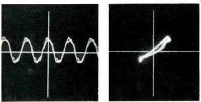
Fig. 7A Same as Fig. 6A, except stop action at 5 kHz. Fig. 7B Same as Fig.
6 B, except at 5 kHz.
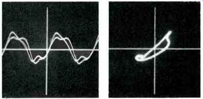
Fig. 8A Same as Fig. 6A, except stop action at 10 kHz. Fig. 8B Same as Fig.
6B, except at 10 kHz.
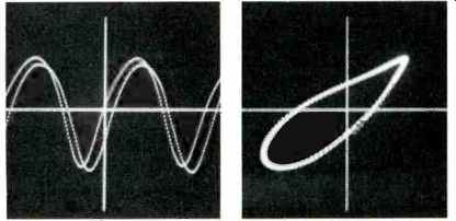
Fig. 9A Same as Fig. 6A, except stop action at 20 kHz. Fig. 9B Same as Fig.
6B, except at 20 kHz.
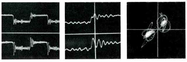
Fig. 10A Left and right channels with a 1 kHz square wave from the CBS STR-112
test record at 3.54 cm/sec. Fig. 10B Same as Fig. 10A, except expanded to
show the leading edge. Note relationship of high frequency phase indicated
by vertical cursor. Fig. 10C Same as Fig. 10A, except left vs. right presentation.
For perfect channel relationships the two bright dots should appear in the
lower left and upper right quadrants.
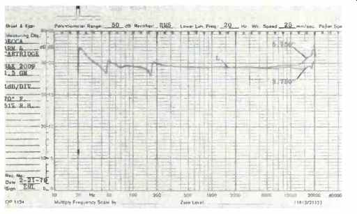
Fig. 11 Scanning loss vs. disc radius. This loss is due to the geometric
relationship between the stylus and the modulated groove. All practical styli
will exhibit this effect to varying degrees. Note increase in size of "glitches" at
45 and 170 Hz.
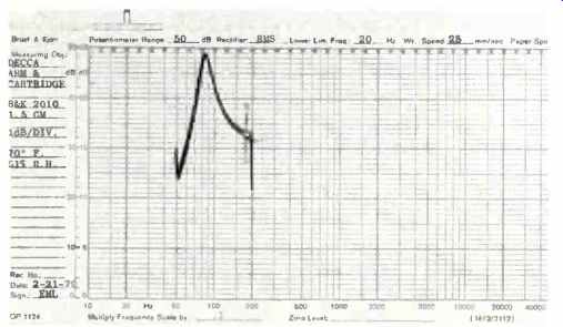
Fig. 12 Low frequency resonance due to effective tonearm mass and cartridge
compliance. Resonance occurs at 8.2 Hz, and Q is 6.3.

Fig. 13 Rise time of the Decca London phono cartridge,18 pS.

Fig. 14 Filtered tone burst at 10.7 kHz with the Shure TTR-103 test record,
Band 4, at 30 cm/sec. Top trace is the left channel and bottom is the right
channel.
The "glitches" at 45 Hz and 170 Hz appear about 2 dB worse in Fig. 11 than they do in Figs. 4 and 5. During the testing of the Decca arm and cartridge, the compliant rubber coupler, which isolates the rear of the arm and counterweight from the main part of the arm, became looser.
Changes in the exact vertical position of the arm due to changes in the relationship between the two opposing mag nets which float the unipivot from the main pillar also occurred. These changes caused the glitch at 180 Hz in Figs. 4 and 5 to shift down to 170 Hz in Fig. 11. During the test for scanning loss, the effects of these changes can be seen as an increase in the Q of these resonances due to these design elements of the arm. The use of opposing magnets to float the arm pillar allows movement between the arm and turntable, and ideally there should be no movement between the arm and turntable. The idea was to reduce the effects of vertical rumble and the transmission of external shocks to the arm/cartridge combination. The coloration in the upper bass range noted by the listening panel can very likely be traced to these resonances. The play in the counterweight and horizontal adjustment weight systems, although partially isolated from the pivot, probably also contributes to the perceived colorations. During the listening tests, great care was taken to minimize these effects, but they could not be totally eliminated.
The low frequency resonance caused by the interaction of the effective mass of the arm and the compliance of the cartridge is shown in Fig. 12. The frequency is a bit lower than desirable and the Q is quite high. The low bass output is affected by this condition and an increase in this range is a direct result of this high Q condition. A large subsonic output can also cause problems in the rest of the reproducing chain.
The rise time of the London cartridge is 18 pS. Figure 13 shows the maximum rise time under the test conditions. An interesting comparison can be made between the Decca London cartridge and the ADC ZLM of a previous report. Although the high frequency resonance of the Decca London is lower at 23.8 kHz than the ADC ZLM at 28.6 kHz, the rise time of the Decca is faster at 18 pS compared to 24 p5 for the ADC. The high frequency resonance is due to the interaction of the effective stylus tip mass and the compliance of the record material. The rise time is a function of the mechanical and electrical attributes of the cartridge alone, without reference to the record material. The effective tip mass of the Decca London cartridge appears to be greater than that of the ADC ZLM and yet it is still capable of faster rise time. An interesting quandary, and yet the listening panel made no negative comments about the lack of extreme highs with the Decca London as they did with the ADC ZLM. The response of the Decca arm and cartridge combination to the 10.7-kHz tone burst on the Shure TTR-103 test record gives another indication of the problems at high frequencies noted by panel members during the listening tests. Spectral information around 10 kHz seems to cause problems for the Decca arm and cartridge. Above 10 kHz, the condition seems to improve. This is verified by the information in Fig. 9 which shows the signal at 20 kHz. It appears less distorted than the 10 kHz signal shown in Fig. 8. The folding in the interchannel phase relationship at 10 kHz shown in Fig. 8B also indicates a more complex problem than the relatively simple phase relationship shown for the 20 kHz signal in Fig. 9B. This inter channel complex relationship can also be seen in Fig. 14 which shows the left (upper) and right (lower) channel responses to the 10.7 kHz tone burst. This test signal allows a further correlation between the quality of reproduction as perceived by the listening panel and technical measurements.
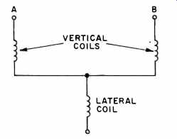
Fig. 15 Coil schematic for the Decca London phono cartridge. A matrix arrangement
of vertical and lateral coils is used to derive the 45°-45° stereo groove
modulation information on the record.
The effect upon the Decca cartridge of various capacitive loading values is not shown, as the capacities would have to be far outside the range normally encountered to be of any consequence. The reason for this immunity to ill effects due to capacitive loading is due mainly to the coils of the Decca London cartridge, the resistance of which is higher than that of most other cartridges (about 2.5 times greater than the ADC ZLM, for example). This means that the Q of these coils s very low, to the point where they act almost as a resistance alone. It also makes measuring the inductance of the Decca London coils a real problem. The coil matrixing scheme, which is used to extract the 45°-45° stereo groove information from what, as described earlier, is a vertical-lateral coil configuration, also contributes to the measurement problem.
Figure 15 shows the electrical schematic of the coils. Each channel consists of a vertical coil which is connected in series with the common lateral coil.
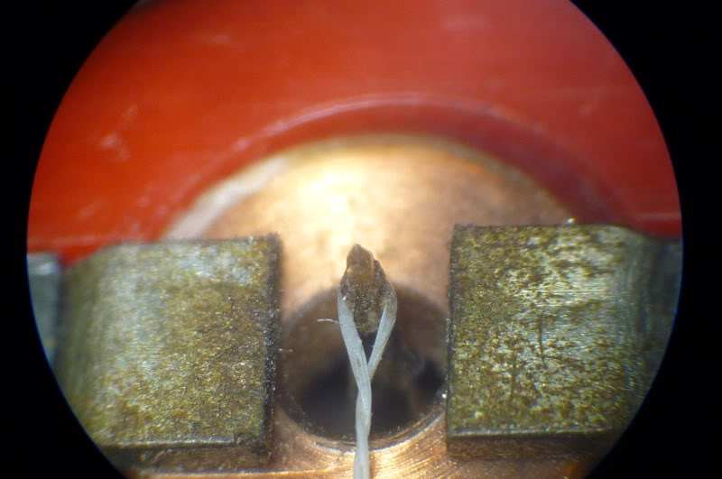
The stylus of the Decca London cartridge is centered in a hole of the lateral pole piece by the tension of a tiny string.
This string is subject to stretching which can result in a change in the vertical tracking angle as well as a misalignment with respect to the pole piece. Cleaning the stylus and pole area is a very delicate operation, yet it should be done frequently if optimum results are to be obtained, and this can lead to problems after a period of time. The Decca London cartridge must be returned to the selling dealer for exchange, and it will ultimately be returned to Rocelco, the North American distributor.
To conclude this report, I would like to emphasize my personal feelings about the Decca London cartridge. While I feel strongly that the basic design ideas of the Decca cartridge are quite well worth pursuing, the present embodiment of these ideas, the Decca London cartridge, is very delicate and at times frustrating. Also, the combination of the London cartridge with the International arm does not seem to be the ideal combination it could be. The same fussiness in setup and handling vs. the great clarity and detail of sound that have engendered a long-standing "love-hate" relationship among some of us is still present. The end result is a caveat to all but truly dedicated and patient audiophiles. A paraphrase of a line from Dickens seems apropos: "It was the best at times; it was the worst at times." The many long hours spent preparing this report should indicate that I feel there is great potential in the Decca design. I hope that I have piqued your curiosity enough that you will try to audition a properly setup Decca arm and cartridge combination. If you do, you may well just become a Decca-phile!
--Edward M. Long.
= = = = = = =
Measured Data
Decca London Phono Cartridge
[Serial No. E-2870]
Left | Right
Inductance, mH 53.5 53.5
Resistance, ohms 2060 2070
Output
1.12 1.30 mV/cm/sec at 45 degrees (B&K 2009, Band 3)
Dynamic Tracking Force, grams required to track B&K 2010 (Gms x 980=dynes)
Band 3, 0 dB (7.07 cm/sec at 45°) 0.5 Band 4, +2 dB 0.7
Band 5, +4 dB 1.0 Band 6, +6 dB 1.2* Band 7, +8 dB 1.5*
*Visual Distortion on 'scope Tracking vs. Radius, grams, (HFS-75,300 Hz, +15 dB, ref. 1.12 x 1 (13 Cm)
Outer Grooves, 0.6 Middle Grooves, 0.7
Inner Grooves, 0.8 Cartridge Mass: 4.1 gms.
Microphony: Resonant clunk when tapped.
Hum Rejection: Good.
High Frequency Resonance: 23.8 Hz.
Rise Time: 18 DS Low Frequency Resonance: 8.2 Hz.
Low Frequency Resonance Q: 6.3.
Recommended Load Resistance: 47 kilohms.
Recommended Tracking Force: 1.5 gms.
Decca International Tonearm
Pivot-to-Spindle Distance: 8.5 in. (21.6 cm).
Pivot-to-Stylus Distance: 9.125 in. (23.2 cm).
Pivot-to-Rear of Arm Distance: 2.5 in (6.4 cm).
Spindle-to-Rear of Arm Distance: 11.0 in (27.9 cm).
Overall Height Adjustment: 1.375-2.25 in. (3.5-5.7 cm).
Tracking Force Adjustment, Maximum 1.5 gms (with Decca London cartridge, 4.1 gm).
Cartridge Weight Range: 3 to 10 gms.
Counterweights: Nonremovable.
Counterweight Mounting: Rubber decoupler for rear of arm and counterweight.
Sidethrust Correction: Opposing magnets with moderate uniformity.
Pivot Damping: Viscous fluid.
Lifting Device: Finger lift with accessory Deccalift available.
Headshell Weight: 6.2 gms.
Headshell Offset: 27 degrees.
Overhang Adjustment: Sliding screw mounts in headshell, with template.
Bearing Alignment: Horizontal adjustable weight.
Bearing Friction: Less than 50 mG in both planes, too low to measure accurately.
Bearing Type: Jeweled unipivot.
Lead Torque: Minimal.
Lead Length: 36 in. (91.5 cm).
Structural Resonances: 45 and 170 Hz.
Base Mounting: 1.125-in. diameter hole through board. Flange mounted with two screws.
General Comments: This is a very delicate and fussy arm to set up and use.
(Audio magazine, Aug. 1979)
Also see:
Decca MK1 Phono Pickup System (Jun. 1970)
= = = =