MANUFACTURER'S SPECIFICATIONS
FM Tuner Section
IHF Sensitivity: 9.8 dBf (1.7 pV).
50-dB Quieting Sensitivity: Mono, 15.6 dBf (3.3 pV); stereo, 35.6 dBf (33 pV).
S/N Ratio: Mono, 80 dB; stereo, 75 dB. THD: Mono, 0.1 percent; stereo, 0.2 percent.
Frequency Response: 25 Hz to 15 kHz, ±2 dB.
Capture Ratio: 1.0 dB. Selectivity: 80 dB.
I. f. Rejection: 100 dB.
Spurious Rejection: 100 dB
Image Rejection: 90 dB.
Subcarrier Rejection: 74 dB.
Stereo Separation at 1 kHz: 50 dB.
AM Tuner Section
Usable Sensitivity: 150 pV/m with internal antenna.
S/N Ratio: 55 dB. Selectivity: 50 dB at 1 MHz.
Image Rejection: 60 dB.
Amplifier Section
Power Output: 120 watts per channel continuous into 8-ohm loads, 20 Hz to 20 kHz.
Rated THD: 0.03 percent.
Rated IMD: 0.03 percent.
Damping Factor at 1 kHz: 100.
Input Sensitivity: Phono 1 & 2, 2.5/5.0 mV; high level, 150 mV.
S/N, "A" Weighted: Phono, 90 dB re: 10 mV input; high level, 95 dB.
Frequency Response: Phono, RIAA ±0.5 dB; high level, 20 Hz to 20 kHz, ±0.5 dB.
Phono Overload: 300 mV/600 mV.
Tone Control Range: Bass, ±10 dB at 100 Hz; midrange, ±6 dB at 1 kHz; treble ±10 dB at 10 kHz.
High-Filter Cutoff: 8 kHz/12 kHz, 12 d B/octave.
Low-Filter Cutoff: 18 Hz/40 Hz, 12 dB/octave.
Loudness Compensation at-30 dB: +3.5 dB at 10 kHz; +7 dB at 100 Hz.
Channel Separation: Phono at 1 kHz, 70 dB; high level, 75 dB at 1 kHz.
Crosstalk: 75 dB at 1 kHz.
General Specifications
Power Requirements: 117 V, 60 Hz, 320 watts.
Dimensions: 22 7/8-in. (58.1 cm) W x 6 1/2-in. (16.5 cm) H x 15 3/4-in. (40 cm) D.
Weight: 49 lbs. (22.2 kg) .
Price: $774.95.
= = = = =
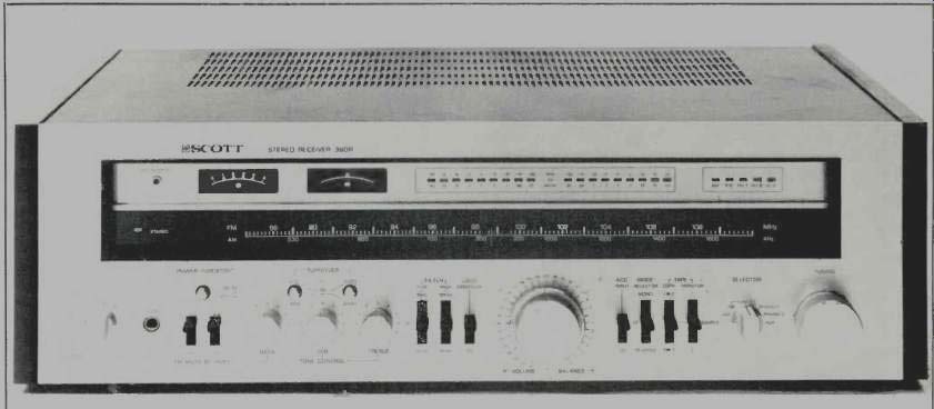
H. H. Scott's most powerful receiver is also its most versatile and feature-laden, all-in-one stereo component. Controls and switches, though plentiful, are logically arranged on the silver-colored front panel and nomenclature (with one exception) is clear and self-explanatory.
The upper section of the panel consists of a well-illuminated dial area with AM and linearly calibrated FM frequencies screened in a light color against a dark background. FM calibration is linear and precise, with marks at every channel width. The usual stereo indicator light is located at the left of the frequency scales. A contrasting light-colored area above the frequency scales contains the twin tuning meters (center of-channel for FM and signal strength which is active in both the AM and FM tuning modes), a circuit-protection indicator light (which illuminates briefly after turn-on and in the event that protection circuits are activated), five program-source indicator LEDs, and two banks of nine LED indicators each of which serves as a power output metering system. These power output level indicators are calibrated in 5-dB steps from 0.01 watts (referenced to 8-ohm loads) to 100 watts.
All operating controls and switches are located along the lower section of the front panel. Rotary controls include a combination power/speaker selector switch (three sets of speakers may be connected, with one or two pairs operable at one time), bass, midrange, and treble controls; dual concentrically mounted, detented volume and balance controls; the program selector switch (which includes two phono input settings, AM, FM, FM-MPX-Filter, and AUX), and a flywheel-coupled tuning knob. The usual phone jack is located near the speaker selector switch. Nearby are a pair of toggle or lever switches, one of which activates the FM muting circuitry, the other labeled "bypass." It is this latter switch which sent us to the owner's manual where we discovered that what was meant was tone-control bypass and that the "On" position means that the tone controls are bypassed, rather than "On." A bit confusing until you figure it out. Above the two toggle switches is a pushbutton switch which deactivates the blinking power-output LEDs, should you tire of gazing at them.
Above the three tone controls are two more pushbutton switches, each of which controls turnover positions for either the bass or treble tone controls. Turnover settings of 300 Hz and 100 Hz are provided for the bass control, with settings of 3 kHz or 8 kHz available for the treble control. Subsonic and high-cut filter switches (with cut-off points of 18 Hz or 40 Hz for the subsonic filter and 8 kHz or 12 kHz for the high-cut filter) come next, along with a loudness compensation On/ Off switch. Four additional toggle switches to the right of the volume/balance controls introduce an "accessory " circuit interruption point (for connection of equalizers, expanders, etc.), select mono, stereo or stereo reverse listening modes, activate either of the two tape monitor circuits, and provide tape copying connections from either of two connected tape decks to the other.
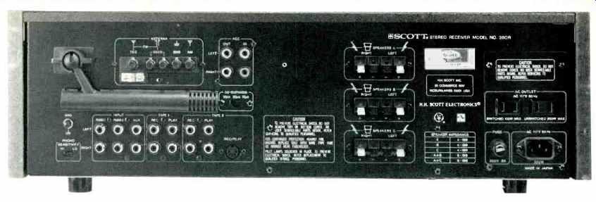
The rear panel of the Scott 390R is equipped with the usual array of phono inputs (for two phono circuits), AUX and tape inputs, tape outputs (the Tape-2 circuits can be fed via a DIN multiple-pin connector as well as by phono-tip plugs), as well as with the aforementioned "accessory" in and out jacks. A slide switch near the phono inputs selects either 2.5 mV or 5-mV input sensitivities (for rated output). Antenna terminals are provided for external AM and 75or 300-ohm FM antenna lines, and nearby is the usual pivotable ferrite bar, AM internal antenna. A three-position slide switch selects either 75-microsecond, 50-microsecond (for use in Europe), or 25-microsecond de-emphasis, the latter required for Dolby FM reception when an outboard Dolby decoder is added.
Three identical sets of color-coded, spring-loaded speaker terminals; two convenience a.c. outlets (one switched, the other unswitched), a line fuse holder, and the a.c. power receptacle for the unit itself complete the rear panel layout.
H. H. Scott has developed a powering format for all of their recently made products which includes a separable line cord that is supplied with each set. This enables the company to ship the same basic unit to various countries around the world, since the appropriate line cord, to fit receptacles in different parts of the world, can be packed with each of the firm's products.
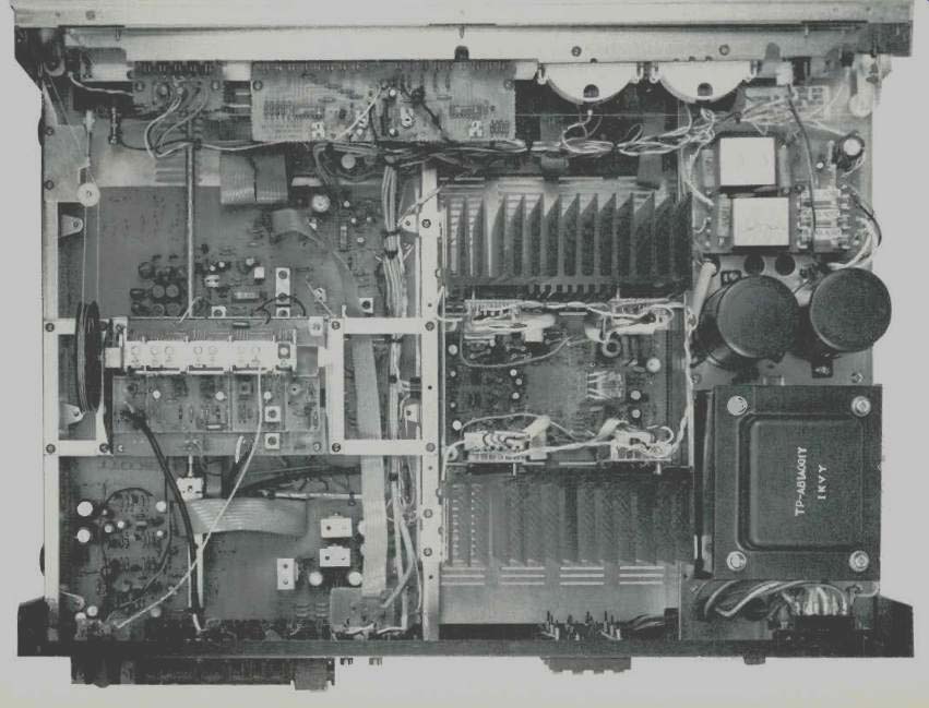
Three dual gate MOS-FETs are used in conjunction with a 5-gang tuning capacitor and a low-noise bi-polar oscillator in the FM front end of the 390R. One transistor and two integrated circuits make up the basic circuit of the i.f. section.
The transistor and first IC provide gain and differential limiting. The second IC provides three additional stages of amplification, wideband quadrature detection, and AGC-, meter and mute-drive circuits. Three dual-element ceramic filters are used to provide selectivity, while the MPX decoder incorporates a phase-locked-loop IC decoder. Subcarrier filtering is accomplished with a three-pole LC filter which is designed to have no interaction below 15 kHz while effectively eliminating the 19and 38-kHz subcarrier components.
The phono preamp-equalizer uses a three-stage configuration. The first two stages provide voltage gain, while the third, a Class-A push-pull stage, provides current gain for the EQ feedback network to prevent slew-induced distortion at high frequencies. The tone-control amplifier is a three transistor design consisting of a single-package differential input followed by a voltage amplifier. When the tone controls are set to center, gain is unity. The tone bypass switch entirely eliminates this circuit from the signal path.
All low-level circuits work in Class A. Subsonic and high cut filters have maximally flat, Butterworth alignment with 12-dB-per-octave slopes.
The power amps consist of a current-mirror, loaded differential pair connected to a Class-A voltage amp with a constant collector load. This drives a fully complementary, Darlington-connected driver and parallel output transistors which provide current gain. The differential transistors are housed in a single package to minimize d.c. offset drift and noise. The driver and output transistors were selected for high cut-off frequency to maximize slew rate and minimize high-frequency distortion.
A split power supply configuration is used with a bridge rectifier and two 15,000pF capacitors to supply dual polarity voltages to the power amps. Phono-preamp, tone-control, and voltage-amp stages are powered from voltage regulators which incorporate capacitance multiplers. The output stage is d.c. coupled to the speakers.
Tuner Section
Laboratory Measurements
Figure 1 depicts the quieting and harmonic distortion characteristics (at 1-kHz modulation) of the mono and stereo FM sections of the 390R. Usable sensitivity in mono measured 10.3 dBf (1.8 NV), marginally short of the 9.8 dBf claimed, but the 50-dB quieting point in mono was better than claimed, with readings of 13.5 dBf (2.6 NV). Signal-to-noise ratio at 65 dBf in mono was an impressively high 81 dB, exceeding the claimed figure of 80 dB. We were surprised to find that the mono/stereo switching threshold on this receiver was set at a fairly high 35.6 dBf (33 NV), which necessarily represents "usable sensitivity" in stereo as well. Since 50-dB quieting in stereo is obtained with just a bit more signal strength than this (36 pV or 36.3 dBf), we would like to have seen Scott set the stereo switching at a lower level, especially since they do provide a strong MPX blend filter for reduction of noise in stereo FM. Scott informs us that the set-up specification on the mono/stereo switching is between 15 and 20 dBf.
Once in stereo, however, best signal-to-noise at 65 dBf, though 2dB short of claims, measured a satisfactory 73 dB. Distortion, at 1 kHz in mono, measured an incredibly low 0.051 percent, increasing to just under the specified 0.2 percent for stereo. At the other test frequencies of 100 Hz and 6 kHz, mono THD was 0.08 percent and 0.2 percent; while in stereo, the measurements were 0.24 percent and 0.4 percent.
Frequency response, displayed in the 'scope photo of Fig. 2, was well within the ±2 dB specified by Scott and in fact exhibited a slight rising characteristic at the high end of a fraction of a dB, unlike many tuner sections which exhibit a rolloff above 10 kHz because of pilot-carrier (19-kHz) filtering. Despite the excellent response out to 15 kHz and above, there was no problem with 19-kHz carrier leakage, which indicates an excellent and precise job of low-pass filtering.
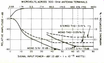
Fig. 1 FM mono and stereo quieting and distortion characteristics.
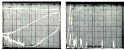
Fig. 2 Stereo FM frequency response and separation. (Center trace is separation
with blend circuit.)
Fig. 3 Composition of crosstalk in unmodulated channel.
The scale used in Fig. 2 (and all subsequent 'scope photos in this report) is 10 dB per vertical division. The lower trace represents the separation capability of the multiplex circuitry.
Separation at the three required test points measured 51 dB (at 1 kHz), 50 dB (at 100 Hz), and an excellent 42 dB (at 10 kHz). The center trace illustrates the rather drastic reduction of separation when the "blend" or MPX-filter position is used. When this setting is employed, separation at 1 kHz drops to 24 dB, while separation at 10 kHz is approximately 8 dB. Users of this receiver are not likely to employ this filter since, as we noted earlier, stereo threshold is set at such a level that stereo reception is fairly noise free at switching and higher input signal strengths.
We have been noting for some time that our meter-measured separation figures are often at odds with the figures obtained by examining the spectrum-analyzer sweeps of separation which we also employ in these reports. The reasons for this discrepancy become clear when you examine Fig. 3 (a display which we will be incorporating in all future tuner and receiver test reports). Two superimposed sweeps are represented here. The first, taken at the left-output with a left only signal modulating the FM carrier shows the "desired" signal (the tall spike at the left of the display), in this case a 5 kHz modulating tone. The second sweep is obtained by reading the right output while the 5-kHz tone still modulates the left input of the stereo generator.
The amplitude of the 5-kHz signal in this undesired channel (shorter spike contained within the earlier, tall spike) is some 50 dB below the "desired" signal. This represents the actual separation. In addition, however, we also see second, third, and fourth order harmonics to the right (having amplitudes which are around 57, 62, and 66 dB below "desired" signal level in the opposite channel) as well as the two sub carrier sidebands located at 33 kHz and 43 kHz. (Note: In this display, sweep is linear, with each linear horizontal division on the 'scope face representing 5 kHz. The log frequency notations do not apply and should be ignored.) Thus, we see that the single-meter reading of "cross talk" really includes more than just the undesired 5-kHz signal.
Capture ratio measured a bit higher than the 1.0 dB claimed, while alternate channel selectivity measured a very satisfactory 83 dB. The i.f. and spurious rejection both equaled or exceeded the 100 dB claimed (the maximum we can measure), while image rejection measured exactly 90 dB as claimed. AM suppression, not specified by Scott, measured a satisfactory 57 dB. AM frequency response for the AM section of the Scott 390R extended from 50 Hz to 3.5 kHz for the 6-dB roll-off points, and a full sweep display of the frequency response characteristic in AM is shown in the 'scope photo of Fig. 4.
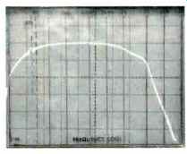
Fig. 4 AM frequency response.
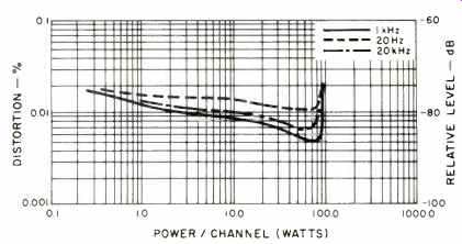
Fig. 5. THD vs. power output.
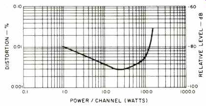
Fig. 6. IM distortion vs. power output.
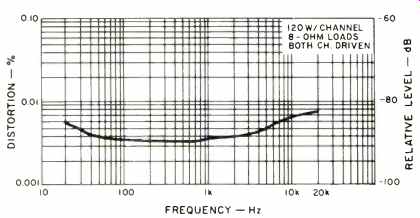
Fig. 7 Distortion vs. frequency.
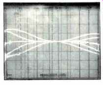
Fig. 8 Bass and treble control range, both turnover settings.
Amplifier Performance Measurements
The power amplifier section of the Scott 390R delivered 149 watts of continuous power, at 1 kHz, into 8 ohm loads before the rated THD level of 0.03 percent was reached. At the frequency extremes of 20 Hz and 20 kHz, it was able to produce 136 watts of continuous sine-wave power per channel for the same rated THD. Power band for rated output (120 watts per channel) extended from below 10 Hz to 40 kHz. At mid frequencies, THD measured 0.003 percent for rated output of 120 watts per channel. Figure 5 plots distortion (THD) vs. power output for 1 kHz, 20 Hz, and 20 kHz, while Fig. 6 plots IM distortion vs. power output. Rated IM distortion was reached at a power output equivalent level of 154 watts per channel, while at rated output, the IM distortion measured 0.0074 percent.
Dynamic headroom for this amplifier section measured 1.9 dB, and slew factor, measured per the new IHF measurement standards, exceeded 5.0. Damping factor, measured for a signal frequency of 50 Hz, measured 75. THD vs. frequency, at rated output, is plotted in Fig. 7.
Frequency response of the amplifier, measured via the AUX inputs, extended from 7.5 Hz to 35 kHz, ±1 dB, while the 3-dB rolloff points were 4 Hz and 65 kHz. Referenced to 1 watt output, high-level input sensitivity measured 13 mV, and signal-to-noise level, referred to 1-watt output with 0.5 volts input, measured 83 dB, "A" weighted. At minimum volume settings, hum and noise was 91 dB below 1-watt output.
Phono input sensitivities were 0.22 mV and 0.44 mV (depending upon the setting of the rear-panel phono sensitivity switch) for 1-watt output. The "A" weighted signal-to-noise in phono, referred to 1-watt output and with 5.0 millivolts of input at 1 kHz, measured 74 dB in the low-sensitivity position and 77 dB in the alternate sensitivity setting. Phono overload measured 300 mV and 600 mV for the two sensitivity settings.
RIAA playback response was absolutely dead accurate from 30 Hz to above 10 kHz, with deviation from the prescribed curve of-0.2 dB at 15 kHz.
Figure 8 represents a 'scope sweep plot of the maximum boost and cut range for the bass and treble controls for each of their two turnover settings. Figure 9 is a display of the maximum boost and cut range of the midrange tone control.
Figure 10 is a graphic 'scope plot of the action of the subsonic and high-cut filters showing the rolloff obtained in each of the two settings available for each of these filter circuits.
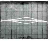
Fig. 9. Midrange tone control range.
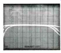
Fig. 10. Action of low and high-cut filters.
Listening and Use Tests
The Scott 390R performed particularly well in FM listening tests, when connected to a properly designed 5-element directional outdoor antenna, pulling in every mono and stereo FM station signal which we normally expect to hear in our listening area, some 20 airline miles from New York City, where most of our local transmitters are located. Using the supplied "indoor" T-wire antenna, weaker stereo signals were unable to exceed the required stereo threshold signal strength and were received monophonically (albeit with noise-free results). Frequency calibration was extremely accurate over all but the very high end of the dial, where a deviation of 140 kHz was noted. Center-of-channel meter indications corresponded well with minimum-distortion tuning.
The power indicating LEDs were extremely accurate in their indication, and though the highest power indicator corresponds to 120 watts per channel, this visually interesting metering system cannot show when clipping or severe overload has occurred in the amplifier section, which, as we have noted, can deliver well over its rated 120 watts per channel.
Phono reproduction was excellent, with no evidence of overload even when listening to heavily modulated direct-to disc records. Transient response rivaled that heard using some of the better separate, d.c.-configured integrated and separate power amps that have recently passed through our lab and listening room. The tone control arrangement, for those who seek a high degree of control, worked smoothly and did not seem to introduce any audible distortion when it was switched in and out of the signal path. Use of the 18-Hz low-cut filter position significantly reduced the IM distortion effects caused by turntable rumble and tended to unveil musical reproduction somewhat without audibly chopping into musical content on any of our musical test records.
The Scott 390R is a full-featured receiver that operates reliably, without generating high heat levels, even when driven to levels approaching maximum output for hours on end. Its suggested retail price seems more than appropriate for a receiver in this category.
--Leonard Feldman
(Adaped from Audio magazine, Aug. 1979)
Also see:
Scott Model R-376 AM/FM Stereo Receiver (Equip. Profile, June 1977)
Scott 438A Integrated Amplifier (Aug. 1983)
Scott (H. H. Scott) Model 477 AM/FM Stereo Receiver (Oct. 1972)
Scott R77S AM/FM Stereo Receiver (May 1975)
= = = =