Manufacturer's Specifications:
Antenna Type: Dipole, indoor, electronically tuned.
Frequency Range: 88 to 108 MHz.
Relative Gain:-2.0 dB.
Directivity: Figure 8 pattern.
Half-Power Angle: 90 degrees.
Output Impedance: 75 ohms.
Standing Wave Ratio: 1.2 or less.
Power Requirements: 18 V d.c., two 9 V batteries, not supplied.
Dimensions: 16-27/32 in. (42.8 cm) W x 6 3/8 in. (16.2 cm) H x 4-7/16 in. (11.3 cm) D.
Weight: 1.9 lbs. (0.86 kg).
Price: $90.00.
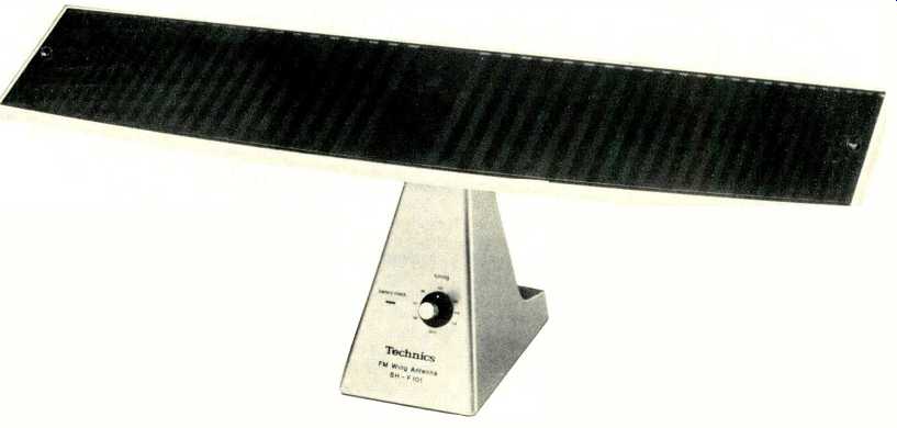
Over the years, we have stressed the importance of using a "good" FM antenna with any FM tuner or receiver. All too often, however, FM devotees who are perfectly willing to invest in a directional outdoor antenna are prevented from installing one for some reason or another. Many manufacturers have attempted to design practical indoor antennas that do almost as good a job, but only a few have met with success. The attractively styled SH-F101 antenna which I used in part of my FM listening tests of the Technics S-424 is a fine example of an indoor FM antenna that really works. To compensate for its extremely short length of only 43 centimeters (a standard FM dipole needs to be 1.8 meters long to be tuned to the middle of the FM band), the Technics indoor antenna features a built-in electronically tuned circuit which brings the gain of this diminutive antenna very close to that of a reference dipole. More importantly, the tuned circuit actually improves the effective selectivity of any tuner or receiver with which it is used.
The SH-F101 also has an excellent "figure 8" directional characteristic which means that by proper orientation of the device, a user can eliminate much of the problem caused by multipath signal reflections so prevalent in many metropolitan areas.
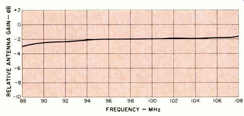
Fig. 1--Relative gain of Technics SH-F101 FM antenna compared to a standard
half-wave dipole cut to 98 MHz.
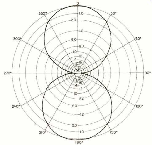
Fig. 2--Directional characteristics at 98 MHz, Technics SH-F101.
The heavy base of the antenna is made of diecast material. The antenna itself is affixed to the base by means of a ball-joint which allows the antenna element to be rotated and tilted to various angles. A short coaxial cable, supplied with the unit, connects between the antenna section and the base, while a longer cable, also supplied, connects from the base to the tuner or receiver with which the antenna is to be used. A switch on the surface of the base has three positions, auto, manual, and battery check. The battery check setting causes an indicator light on the opposite surface of the base to illuminate if battery voltage is still adequate. The manual switch setting allows the antenna to be used with any tuner or receiver and requires that the user tune a small knob until its pointer indicates the frequency to which the associated tuner or receiver is tuned. Since frequency calibration is only nominally accurate and somewhat vague, the best way to use the tuning control is to observe the signal-strength meter on the tuner or receiver with which the antenna is used. Once correct tuning of this knob has been accomplished, the antenna element itself should then be rotated and angled for best reception.
When the antenna is used with current models of Technics tuners or receivers, such as the SA-424 tested for this report, the selector switch on the antenna may be set to the auto mode.
In this setting, not only are batteries not required for the antenna, but it is not even necessary to operate the little tuning knob on the antenna. Instead, a voltage appearing at the 75-ohm antenna terminal on the associated Technics tuner or receiver varies with the frequency to which the Technics synthesized tuner or receiver is tuned. Under these conditions, the user has only to physically orient the tuner for best reception and the electronic tuning is taken care of by the voltage coming from the associated Technics tuner or receiver. As I pointed out to the folks at Technics, however, the owner's manual for the SA-424 says nothing about this clever antenna tuning method, and I would never have known about it had I not had a conversation with the technical folks at Technics during the course of my tests. It's a very nice feature, but ought not to be kept a secret by its makers!
Laboratory Measurements
Gain of the antenna over the entire FM frequency band was compared with the gain of a reference dipole, and results are shown in the graph of Fig. 1. The "0 dB" in this graph corresponds to the gain which a standard dipole (half-wave exhibited, when cut to 98 MHz, the middle of the FM band). As for directionality of the antenna, it exhibited an almost perfect "figure 8" directional pattern, as shown in Fig. 2.
Summary and Use Tests
Many FM listeners make the mistake of purchasing an indoor antenna in hopes that it will provide them with as much signal power as an outdoor antenna. No indoor antenna I know of will provide this result. More often than not, however, lack of signal strength is not the problem. Usually, FM listeners want to eliminate multipath interference and other noise and interference sources. It is for these purposes that an antenna such as the Technics SH-F101 is ideally suited. The antenna worked very well not only with the SA-424 receiver, but with other tuners and receivers that were in my lab at the time of these tests. The increased selectivity brought about by the tuned circuitry of the antenna was beneficial when I tried to separate closely spaced (in frequency) signals on my normally crowded FM dial. The Technics SH-F101 is truly the next best thing to a multi-element outdoor antenna--and that is quite high praise for any indoor antenna.
-Leonard Feldman
=================
(Adapted from Audio magazine, Aug. 1981)
Also see:
Technics SA-424 FM/AM Stereo Receiver (Equip. Profile, Aug. 1981)
Technics by Panasonic SA-8000X 4-Channel/2-Channel Receiver (Equip. Profile, Nov. 1974)
Technics by Panasonic Quadraphonic Tape Recorder Model RS-740US (Equip. Profile, Jul. 1973)
= = = =