Manufacturer's Specifications:
Power Output (20 Hz to 20 kHz):
100 watts rms into 8-ohm loads; 200 watts, continuous, into 4-ohm loads;
400 watts, continuous, into 2-ohm loads.
Rated THD: Less than 0.2% maximum at 100 watts, 20 Hz to 20 kHz, into 8 ohms; 0.3% at 200 watts into 4 ohms; 0.4% at 400 watts into 2 ohms.
Frequency Response: 3 Hz to 140 kHz, +0,-3 dB. at 1 watt output.
Input Impedance: 50 kilohms shunted by 1 nF.
SMPTE-IM Distortion: Less than 0.2% at rated output into loads of 1 ohm or higher.
Gain: 26 dB.
Dimensions:
Front panel, 17 1/2 in. W x 8 1/2 in. H (44.5 cm x 21.6 cm); optional front-panel width, 19 in. (48.3 cm).
Chassis (including heatsinks, handles, and rear connectors), 17 1/2 in. W x 8 1/4 in. H x 22 1/16 in. D (44.5 cm x 21.2 cm x 56 cm).
Weight: 65 lbs. (29.5 kg); shipping weight, 90 lbs. (40.9 kg).
Price: $9,600 per pair.
Company Address: c/o Madrigal Audio Laboratories, P.O. Box 781, Middletown, Conn. 06457.
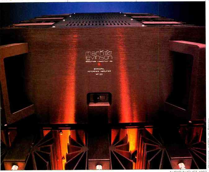
The No. 20 monaural amplifier sits at the top of the prestigious Mark Levinson component line. It might have been designated the ML-20, but it is the first Levinson amplifier created under the ownership of Madrigal Audio Laboratories, hence its slightly different name. Still, it resembles earlier Levinson amplifiers, with its thick, engraved faceplate, extensive heat-sinking, and Camac coaxial input connectors (instead of RCA-type phono jacks). Like other Levinson amplifiers, it also carries a premium price.
Insofar as the No. 20 is a fully regulated, Class-A, 25-watt amplifier with modular construction, it can be viewed as a direct descendant of the previous Levinson flagship, the monaural ML-2. The No. 20 features regulation of power supplies for all audio stages, as the ML-2 did, but it also introduces some new circuit features to the line, such as separate power supplies and regulation for both positive and negative power-supply rails, extensive a.c. line filtering, a soft-clipping circuit, and an output stage that requires no load-isolation network.
This amplifier weighs in at 65 pounds, and two are needed for stereo operation. Each No. 20 is rated at 100 watts into 8 ohms: if more power is required, a pair can be bridged using the special inverting and noninverting inputs to yield rated power of 400, 800, and 1,250 watts into 8, 4, and 2 ohms, respectively. Distortion and bandwidth ratings are not given for bridged operation, and the No. 20's 10-ampere fuses may not allow a pair of these units to deliver the rated 1,250 watts into 2-ohm loads for very long. Unlike earlier Levinson amplifiers, the No. 20 has a balanced input with an XLR-type three-pin jack, in addition to its unbalanced Camac-connector inputs. For optimally low noise when either unbalanced input is used, the balanced input should be shorted with a plug supplied for this purpose.
The 5/8-inch-thick engraved faceplate and the six radial-finned heat-sinks make the No. 20 the largest 100-watt audio amplifier we've seen. Actually, most of the audio circuitry is contained within the central chassis, which accounts for only 9 3/4 inches of the amplifier's 17 1/2-inch width.
The remaining width is accounted for by six elaborate heat-sink assemblies that line the amplifier's sides. Each sink extends 4 1/4 inches from the side of the chassis, has 14 fins, and contains a p.c. board holding numerous power transistors. The large chassis and multiple fins allow the No. 20 to run in Class A at full power into 8 ohms (which requires the dissipation of 500 watts of heat at idle) without a noisy fan.
Installation of the No. 20 is facilitated by solid handles at front and back. We found it easiest to move the amplifier by grabbing one front handle and the rear handle diagonally opposite it. The front handles are angled outward, an attractive design feature. The standard faceplate is 17 1/2 inches wide, but a 19-inch-wide plate may be ordered (at no extra charge) for rack mounting.
A single red LED is at the center of the front plate. As on other Levinson amplifiers, the only control is a rocker-type power switch. This switch, a single-pole type with a relay trip coil tied into the protection circuitry, controls only the hot side of the a.c. line. All other a.c.-line components are duplicated on both the neutral and hot sides of the line.
The rear panel provides a wide range of signal connection options, more than we've seen on other premium-priced amplifiers. These include the socket for the detachable a.c. cord (just under the 10-amp fuses for each side of the a.c. line) and a chassis-ground binding post. Toward the center of the back plate are the two outputs. These utilize special gold-plated, high-current (80-ampere peak) jacks for the Fischer self-locking speaker connectors supplied with the amplifier. The manual suggests that the owner or dealer solder the speaker cable into these connectors. (Special adaptors with five-way binding posts attached to a pair of Fischer plugs are available from dealers on special order.) At the far right of this panel is a balanced-input XLR jack and, below it, two Camac input jacks for the inverting and noninverting inputs. The locking Camac devices are used in all Levinson components; they are designed to make ground contact before signal contact on insertion and to break signal before ground contact on removal. These connectors avoid the potentially woofer-damaging hum that can occur when conventional phono plugs become loose or are accidentally removed while the amplifier is turned on. Cables to fit these connectors (both Camac-to-Camac and Camac-to-RCA) are available from Madrigal and from some independent cable companies; Madrigal also sells male Camac connectors.
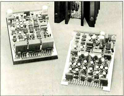
above: Some of the amplifier's circuit modules, showing the gas-tight
Varicon edge connectors.
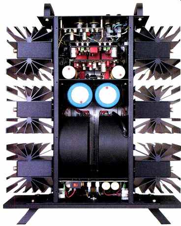
The No. 20's exterior is all-black anodized aluminum. The amplifier is constructed around a narrow, deep, U-shaped chassis, formed from 0.090-inch stock, to which the front plate, rear panel, and heat-sink subassemblies are attached. Small p.c. boards are mounted in the center of each of the six radial heat-sinks to accommodate regulators, drivers, and output transistors. The front heat-sinks house regulator circuitry and contain 10 transistors each; the middle sinks contain a thermal cutout, a pre-driver, three paralleled drivers, and four paralleled output devices. The rear heat-sinks contain four output devices (paralleled with those on the middle heat-sink) and a single, small transistor to control bias. The amplifier is physically symmetrical, with all heat-sink-mounted circuitry for the positive rail on one side, and all such circuitry for the negative rail on the other.
The top panel is held on by eight stainless-steel, button-head, hex-driven machine screws. Removing it reveals a showcase of superb construction and high-quality components. The circuit card nearest the front panel is the power supply, with movable jumpers and a switch by which the dealer can select 100-, 120-, 200-, 220-, or 240-V a.c. mains operation. This card also contains power-on surge circuitry with turn-on delay. On the motherboard, extensive a.c. line filtering is carried out by r.f. capacitive bypasses and large metal-oxide varistors (MOVs). Circuitry here protects against line voltage spikes and shuts down power under such fault conditions as over-voltage or prolonged, high current draw. The partitioned-off power-supply compartment contains two large, potted, 600-VA toroidal transformers-one for each rail-mounted on the chassis side panels. During assembly, these transformers are rotated in their mounts relative to one another to achieve lowest possible hum in the output signal. Next come two 24,000-uF electrolytics which are bypassed with film capacitors. Two 35-ampere bridge rectifiers sit between the transformers and filter capacitors.
Another compartment holds three vertical cards, the first two of which plug in. Regulator voltage-gain and protection circuits sit on the first card. The second card, which has a black aluminum heat-sink plate on its back, contains audio voltage-gain circuitry. The third card, holding additional protection circuitry, is bolted to the rear panel. A mother board and discrete fault-sensor wiring interconnect all of these functions. Six ears on the motherboard protrude through slots in the side panels to connect to circuitry on the six heat-sink assemblies.
By dividing the circuitry into so many modules, as was done on the earlier Levinson ML-2, Madrigal claims they can test and match internal parts more accurately. They further claim that, as a result, any two No. 20 amplifiers should match each other perfectly. This modularity also greatly increases ease of service in the field, thus avoiding the need to ship the entire amplifier (which weighs 90 pounds when boxed) back to the factory for service. It also allows the manufacturer to offer updates to the amplifier. (Madrigal says, however, that they intend to offer such updates infrequently, and only after many significant production changes have accumulated.) To a great extent, the amplifier can be disassembled and put back together as easily and precisely as a rifle. To remove any of the six heat-sink assemblies, each of which is secured by two bolts, one must first release the knurled nuts holding a protective cover in place, then simply unscrew two hex spacers to unplug the assembly.
Good signal contact is maintained between these plug-in subassemblies by Elco Varicon contacts which connect each heat-sink to the main circuit board. These mil-spec connectors employ 45° beveled tines which form gas-tight surface junctures rated for over 1,000 insertions. They carry a high (10-ampere) current rating and have extremely low (0.006-ohm) contact resistance.
Circuit-board and component quality is as high as we have seen in a hi-fi unit. All p.c. boards are double-sided, high-quality glass-epoxy types. The circuit traces on the boards are curved to reduce the interactions possible with parallel traces. There is a minimum of point-to-point wiring, aside from the 6-gauge, oxygen-free-copper bus lead from the motherboard to the output connectors. Inputs are soldered directly to the circuit board. All audio signal paths employ soldered connections, except for the Varicon connectors at the heat-sinks and the plug-in audio circuit cards.
No trendy designer-label capacitors can be found in the No. 20. Madrigal's use of mil-spec RN-60 resistors, metal-can transistors, and Elco Varicon connectors is ample evidence of the No. 20's extraordinary parts quality. In particular, better quality capacitors are used extensively to bypass critical circuit areas. For example, although the electrolytic capacitors used are the best available switching-grade types, each is bypassed by both a foil-type polypropylene capacitor of a small value and a metallized polypropylene capacitor of larger value. The manufacturer claims that this utilizes the best parts of each capacitor type's equivalent series impedance-versus-frequency curve.
The ruggedness and reliability of the No. 20's circuit construction stem from the manufacturer's experience in maintaining many ML-2 amplifiers in the field over the past 10 years. Thanks to its sturdiness, the No. 20 should provide 10 to 25 years of maintenance-free operation.
Circuit Description
The No. 20's circuitry features Class-A biasing, regulated power supplies, extensive protection, and conservative circuit configuration. Of course, each No. 20 is a monophonic amplifier, so crosstalk and other interactions between channels in a stereo setup are kept to a minimum. Normally, when we speak of "dual mono," we are referring to two separate amplifiers on a single chassis, each with its own power supply. The No. 20 takes this concept one step farther: It uses dual-mono supply rails! Each half of the waveform has its own power supply and regulator.
Fixed-bias Class-A amplifiers, favored by audiophiles, are very inefficient because they dissipate as much power during quiet passages as they do at full power. With an amplifier delivering high current and reasonable power, a pair of amps can demand more electricity than the average home's wiring can draw from the power company. Levinson's solution is to fix the bias at a reasonable level and design the circuitry to move into Class-AB operation for music peaks, doing so at lower output levels as the load impedance falls below 4 ohms.
===============
ARC WELDING WITH AN AMPLIFIER
An enthusiastic reviewer might call a beefy amplifier an "arc welder" as an exaggerated compliment to its ruggedness and current-handling capacity. However, no one would really expect an amplifier to actually melt steel. Almost no one, that is, except this reviewing team. We say this amplifier is an arc welder and back up this statement with a photograph (Fig. B1) of two 0.05-inch steel plates welded together by a pair of Mark Levinson No. 20s.
Arc welding is accomplished by creating an electric arc that melts metal. The molten sections of the items to be joined flow together and are then allowed to cool. In practice, the power source is connected to the two pieces to be joined and to a flux-coated welding rod. The arc is struck by momentarily shorting the rod to the work pieces. The flux is vaporized, forming an ionic conducting path for the arc and cleaning the met al. The arc stabilizes at about 100 amperes and 30 V (creating temperatures of 3,000° F), depending on the thickness of the metal and welding rod. If this sounds like the world's worst amplifier load, you're right! Coauthor Clark summoned Paul Grzebik to carry out the task. Paul has the reputation, in Detroit's technical community, for a willingness to try anything once, from building a parade float to scaling a TV transmitting tower. He readily agreed to our assignment. Clark drove both No. 20 amps with a 1-kHz square wave to full output into a series resistor mixing network that combined both amplifier outputs in parallel to obtain the high current needed. After experimentation (and several blown line fuses), approximately 1 ohm was found to deliver the maximum current for starting and sustaining the arc.
Wearing a mask and gloves (the intense blue light from the arc can burn the unprotected retina, while molten metal can splatter on the hands), Grzebik began welding. The arc turned out to be a fairly effective plasma tweeter, creating strong 1-kHz square-wave sound radiation that required wearing ear protectors as well. Grzebik completed a small weld and, impressed, pronounced it satisfactory.
After the welding, the No. 20s, still only lukewarm, were again put on the test bench. Distortion tests verified that no change in their performance had resulted from this extraordinary exercise.
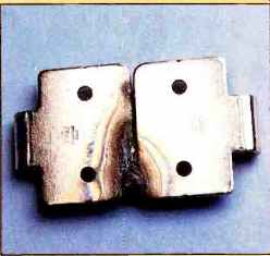
Fig. B1--Results of the arc-welding experiment.
What's the point? With this test, Clark verified his confidence in the exceptional output capability and comprehensive protection built into these amplifiers. A few other amps might be able to weld steel without destroying themselves, but the No. 20s were certain to survive the experiment.
One note: Don't attempt this feat yourself unless you are an accomplished welder, have the proper equipment, and are using amplifiers with extraordinary protection circuitry and output stages that can handle current extremes. Injury to yourself and destruction of lesser amplifiers may result. Don't expect manufacturers to repair your damaged amp un der warranty, either!
L.L.G. and D.L.C.
==============
Most amplifiers do not use the No. 20's level of regulation (regulation of all stages, including outputs) because of increased cost and decreased power available for momentary music peaks. Unregulated amplifiers, on the other hand, are somewhat dependent on the open-circuit voltage of the a.c. power line. The No. 20 is highly independent of the power line. Even if a brownout smokes your air conditioner, the No. 20 will play with full power. The regulated power supply in the No. 20 actually does more to stabilize and purify the power source than even the expensive line conditioners sold for use with computers.
Madrigal has designed a highly sophisticated protection circuit for this amplifier. Some protection schemes have interfered with sonics by mistaking a difficult but normal load for a fault. This unneeded protection results in snap ping sounds or premature clipping. The No. 20's protection scheme analyzes and handles an extremely broad range of load conditions without sonic interference. Part of this ability derives from the No. 20's overbuilt "eight-up, eight-down" output stage, which uses eight transistors in each half of the push-pull circuit. While even a simple protection scheme could protect such circuitry without affecting performance into normal loads, the No. 20 goes much farther, sensing and reacting to only those extreme conditions that the amp is not designed to handle.
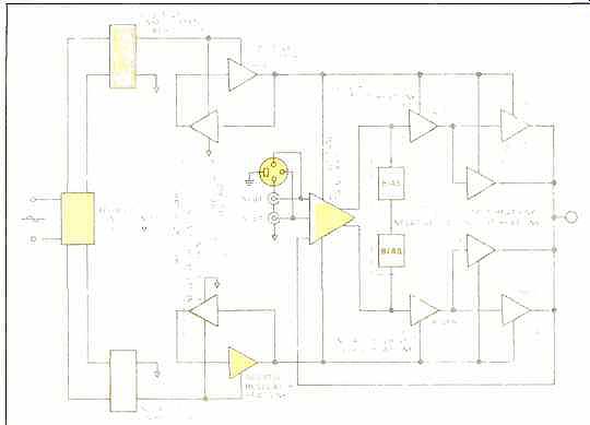
Fig. 1--Block diagram showing the No. 20's main functional subsystems. Note
the independent power supplies and regulators for both the positive and negative
voltage supplies, and the use of balanced inputs plus positive and negative
unbalanced inputs.
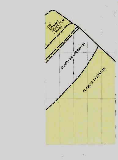
Fig. 2--Maximum power envelope. Note the straight-line relationship between
log power and log impedance, showing that the No. 20 behaves as a true voltage
source. Dashed lines are boundaries between Class-A and Class-AB operation
and fuse limits for different time periods. Line dividing Class-AB and IHF
dynamic power regions is limit of continuous operation: line just above that
is the 4-hour fuse limit, with the 1-hour fuse limit slightly higher; upper
boundary of IHF dynamic power region is protection limit.
The No. 20's protection consists of a fusing system, electronic limiting, and the on/off relay trip switch. This system continuously monitors the a.c. mains voltage, the current and voltage level of the positive and negative power sup plies, the amplifier temperature, d.c. offset level, power dissipation in the output stage (particularly the influence of phase angle), and short-circuit conditions at the output. A detector circuit located on the first plug-in card monitors the d.c. offset at each channel's output and will trip the a.c. line on/off switch if the offset becomes excessive. Three thermal cutouts are used, one for each of the two middle heat-sinks and one at the center of the chassis. These will trigger the No. 20's shut-down circuitry if their temperature exceeds 80° C (176° F).
A new type of soft-clipping system is also used in the No. 20. A voltage-limiter circuit, primarily in the second voltage-gain stage, monitors the level in this stage and reduces the amplifier's open-loop gain as the signal nears a level which could cause saturation here or in subsequent stages. Additional parts of the system, residing in the first voltage-gain stage, prevent saturation at the input. Because the circuit's action is gently contoured, rather than abruptly beginning at some preset point, it does not generate nearly as much higher-order harmonics as such limiting circuits usually do.
Like many high-end amplifiers, the No. 20 uses almost all bipolar transistors, in a straightforward configuration but with an unusually large number of support parts to improve linearity and reliability. The regulated power supplies are an example of this complexity. The simplest bipolar supply can be built with five components. In the No. 20, more than 200 components-fully half of the circuitry-are devoted to this function.
The amplifier's circuitry is shown in Fig. 1. On the a.c. mains card, a resistor, shorted by a relay, is wired in series with the transformer primary to reduce inrush current. A transistor time-delay circuit operates the relay, which by passes the series resistance after about 1.5 S. This turn-on surge-delay circuitry prevents damage to the electrolytic filter capacitors and other power-supply circuitry, which could result from repeated, rapid turn-on and turn-off of the power switch.
Separate power supplies for each d.c. rail are provided. Each rail has its own power transformer, full-wave bridge rectification, and high-quality filter capacitors. To prevent mechanical noise from the d.c. sometimes found in Europe an or older American a.c. power grids, the two transformers have a special "anti-buzz" circuit.
Following the power supplies, the No. 20 has completely independent, non-tracking regulation for each rail. This is accomplished by a very substantial regulator amplifier, composed of differential amplifiers (on the regulator card) driving series-pass regulating output stages (on the heat-sinks). Madrigal claims that the regulators' on-board voltage sensing provides negative-feedback error correction, using operational-amplifier techniques. The regulating system prevents d.c. voltages from fluctuating due to severe current demands from the load. This unusual feature yields a very low power-supply impedance. The regulated d.c. voltage rails are further filtered by two 9,000-uF capacitors bypassed with various film capacitors.
Although the ML-2 has power-supply regulation for all its audio stages, the amount of regulation decreases above 5 kHz. In contrast, the No. 20's regulation is rated from d.c. to 22 kHz. The manufacturer claims that this means the power-supply output is ripple-free down to four decimal places, even beyond 50 kHz.
All amplifying stages in the No. 20 are direct-coupled. The first signal stage (on the audio voltage-gain card) consists of a cascode differential amplifier biased by a current sink.
The signal input transistors are two matched NPN types. The outputs of these transistors are direct-coupled to a pair of N-channel junction FETs which act as the output section of the cascode. The second stage is a cascode differential amplifier with a current-mirror load. This stage uses PNP bipolars, and its current mirror uses NPN bipolars.
The second-stage differential amplifier, in turn, feeds the pre-drivers, which are mounted near the drivers on the heat-sink. These low-power, wide-bandwidth devices act as the first current-amplifying stage; they feed three paralleled complementary emitter-follower drivers which then drive the bases of the output transistors. All voltage-gain and driver stages maintain Class-A operation at all levels, even if Class-AB operation is required from the output stage.
That output stage, which occupies four of the six heat-sinks, uses 16 parallel output transistors (eight PNP and eight NPN) in a complementary push-pull design. The transistors are rugged, wide-band, high-power (200-watt) types.
This stage is heavily biased to remain in Class-A operation at 8 ohms up to rated power. Each transistor in both the driver and output stages has its own individual negative feedback. The open-loop gain of the amplifier itself is approximately 80 dB. The manufacturer claims that the No. 20 employs 50 to 60 dB of negative feedback.
The No. 20 is unusual in that it has no output load-isolation network, so the output stage's very low impedance is presented directly to the speakers. As a result, the damping factor remains high, even at the upper frequencies.
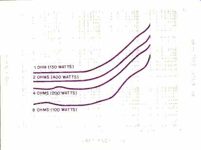
Fig. 3--THD + N versus frequency for four load impedances and power levels.
Though distortion rises at higher frequencies and lower impedances. it remains
generally low.
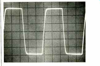
Fig. 4-Large-signal, 20-kHz square wave at 100 watts into 8 ohms, showing
5-4 rise-time. (Scales: Vertical, 10 V/div.; horizontal, 10 µS/div.)
Measurements
Before any measurements were taken, the No. 20 was run for an hour at 33% of rated power, or 33 watts per channel into 8-ohm loads. This standard preconditioning period, normally taxing for Class-AB amplifiers, poses no problems for Class-A amps. The No. 20, instead of being cycled on and off by its thermal protection circuits during this period, as some Class-AB amps are, actually cooled down a bit! The No. 20 is a very unusual amplifier, and standard IHF measurements do not fully reveal its power capabilities or its sonic attributes. In fact, the owner's manual reads, "The correlation between published specifications and sonic quality is unreliable. A list of numbers reveals virtually nothing. All technical measurements must be subject to qualitative as well as quantitative interpretation." We agree that a modern amplifier's specs don't tell us what it sounds like.
Still, we shall report measurements, some of which can be related to the performance of 100-watt amplifiers in general, and others that show how special the No. 20 actually is.
The Madrigal design team had their own list of priorities for this amplifier, which apparently was topped by the ability to deliver power into a very wide range of difficult loads.
Accordingly, our first task was to define the limits of the amplifier's power output. The unit's fully regulated power supply is designed to handle the most unfavorable loads under brownout conditions. Measured into 4-ohm loads, the No. 20 maintained its output voltage between 31.5 and 31.7 V (234 to 251 watts) at a.c. line voltages from 90 to 132 V.
Levinson's official power ratings for the No. 20 are 100 watts into 8 ohms and 200 watts into 4 ohms. The output voltage at both ratings is 28.28 V. This shows that the amplifier is a true voltage source, for only a source such as this will deliver twice the power when the load impedance is halved.
Within the limits of its fusing and protection circuitry, the No. 20 maintained the same 28.28 V into loads of 8, 4, and 2 ohms. The current drawn from the a.c. line at 400 watts into 2 ohms was 12 amperes, which exceeded the 10-ampere rating of the a.c. fuses. Only when coauthor Clark used a 1-ohm load did a line fuse blow (at 18 amperes!) as he neared the 28.28-V output rating of the No. 20 (which would have been 800 watts into 1 ohm). After replacing the fuse, he limited the line current to 10 amperes (130 watts into 1 ohm) and retested with a 1-ohm load. The amplifier performed beautifully, showing maximum distortion of 0.42% THD + N at 20 kHz. This distortion level would not be audible on music and is comparable to published ratings for high-quality tube amps driving standard loads; here, we were using one-fourth of the amplifier's minimum rated load! Figure 2 shows that the No. 20's power output almost exactly doubles with every halving of load impedance. This held true over the entire impedance range we measured, from 16 ohms to 0.5 ohm, and demonstrated how the No. 20's regulated power supply maintained virtually constant maximum voltage over that load range. The dashed lines perpendicular to the power-output curve are current limits which define the following performance boundaries: Shift from Class-A operation to Class AB (7 ohms at 140 watts);
limits of fuse operation for continuous, 4-hour, and 1-hour periods (10 amperes, 11 amperes, and 13.5 amperes, respectively), and the protection-circuit limits (0.7 ohm at 800 watts for 20-mS pulse tests). The No. 20's tightly regulated power supply does have a down side; it limits both dynamic headroom and clipping headroom to 1.1 dB (129 watts). In fact, this headroom is not "dynamic" at all; it simply is a reflection of Madrigal's conservative underspecification of the power rating.
A surprise came when we checked the No. 20's current-delivery capacity. The amplifier sensed our standard 0.1-ohm load as a short circuit and limited the 20-mS current output to 18 amperes. Using the same 20-mS pulse test into a 0.67-ohm load, we found that the No. 20 could deliver 36 amperes continuous (50 amperes peak) current. This current-delivery capacity into 0.67 ohm is as high a current output as our lab has found for an audio amplifier. The combination of high current capability and short-circuit protection inspired us to experimentally use the No. 20 as an arc welder (see sidebar). Although we do not recommend this test (it will void most warranties, destroy lesser amplifiers, and expose to injury those who are not experienced welders), the No. 20 proved itself to be rugged, stable, and able to handle this bizarre task.
Voltage gain was found to be 26 dB into 8-ohm loads. IHF sensitivity for 1 watt output into 8-ohm loads was 141 mV.
Figure 3 shows THD + N as a function of frequency for four load impedances and power-output levels. Overall, distortion was lowest at low frequencies, low levels, and high impedances. It rose gradually as the load impedance dropped but was always well within its rated limits. At 20 kHz, where distortion was highest, THD + N at 100 watts into 8 ohms remained below 0.07%; into 4 ohms at 200 watts, it was below 0.13%, and at 400 watts into 2 ohms, it remained below 0.22%. Even at 1 ohm, THD + N never surpassed 0.42%. At frequencies below 1 kHz, THD + N was less than one-tenth of these maximum values.
IHF signal-to-noise ratio (referred to 1 watt into 8 ohms) was 79.0 dB, wide-band, and 89.0 dBA. Part of the noise was contributed by an a.c. synchronous buzz. These figures are not the best we have measured, but no noise was audible in use with medium-efficiency speakers.
Frequency response at 1 watt into 8-ohm loads was 3.4 Hz to 168 kHz, +0,-3 dB. Input impedance was 50 kilohms below 1 kHz but dropped off as frequency rose, measuring 9.2 kilohms at 20 kHz.
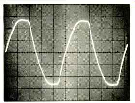
Fig. 5--Same as Fig. 4. with 2-1.LF capacitor paralleling the 8-ohm load,
simulating the load of an electrostatic speaker. The large phase angle activates
the amp's protection circuit, and limiting occurs. Note how rise-time increases
from 5 to 15 S.
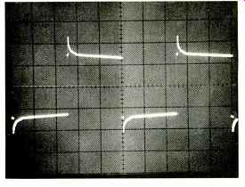
Fig.
6--Large-signal, 100-Hz square wave at maximum output into a 1.8-ohm resistance
in series with a 2.25-mH inductor. Although the limiting circuitry is not tripped
by this "worst-case" load, the amplifier has difficulty
sinking the flyback current stored in the inductor. Note the peaks at each
leading edge as the current rushes back into the amplifier from the inductor;
this is still very good performance. (Scales: Vertical, 10 V/div.; horizontal,
2 mS/div.)
Damping factor was measured next. To minimize resistance in our test-lead connections, we soldered our leads to the Fischer speaker plugs; according to Madrigal, this is the best way to make speaker connections. We also checked our damping-factor test setup by measuring the lead resistance when the connectors were unplugged from the amplifier and shorted together. Our measurements showed a maximum damping factor of 899 at 40 Hz, falling to 129 at 20 kHz. These are excellent figures, verifying the low impedance of the output stage.
Rise- and fall-times, measured with a 20-kHz square wave at rated power into 8 ohms, were found to be 5µS up and down, as shown in Fig. 4. With this purely resistive load, there was no ringing or other anomalous behavior, even near clipping. The amplifier's slew rate was 14.5 V/µS down and 13.0 V/µS up. The IHF slew factor was 2.5, the ratio between 50 kHz (the maximum input frequency at reference input level for clean, 100-watt sine waves when driving 8-ohm loads) and 20 kHz.
Determined to explore the boundaries of the No. 20's performance, we tried two other, more difficult, loads. To approximate the capacitive load of an electrostatic speaker, we paralleled a 2-µF capacitor across the 8-ohm resistor; the results are shown in Fig. 5. Most amplifiers would show some ringing on such a load, but this is usually due to the output network, a feature not found in the No. 20. Instead, we see evidence of the protection circuitry (detecting the large phase angle in this reactive load), which rounds off the edges of the square wave, increasing the rise-time of the amplifier from 5 to 15 µS. This effect is also seen at lower power levels, to a lesser degree.
The second "torture test" load was a 2.25-mH inductor in series with 1.8 ohms. This highly reactive load is not specified in any standard amplifier test; it might be approximated if eight high-efficiency dynamic loudspeakers were wired in parallel. The No. 20 handled this test beautifully for most frequencies. However, after changing test conditions a number of times, Clark did find one test signal, a 100-Hz square wave at maximum output, which "pushed the envelope" of the No. 20's performance domain when fed into that brutal load. This combination of load and test signal would trip most amplifiers' protection circuitry. The No. 20's protection did not cut in, but as Fig. 6 shows, the amplifier was not altogether successful in managing the load. The stored energy in the inductor produced spikes at each leading edge, as the No. 20 could not completely sink the energy released from the inductor at those points in the cycle. To its credit, the No. 20 showed no such anomalies at high frequencies. Meanwhile, the inductor itself became too hot to touch.
Use and Listening Tests
First impressions are important, and unpacking a pair of No. 20s gave us a sense of the care Madrigal takes with its product. Huge cartons, fitted with massive plastic "shipping buttons" at their base, ensure safe transit and handling in this day of express air service and overstressed forklift truck drivers. Styrofoam inserts protect the amplifiers' finish, and the large front and rear handles on the units themselves make them easy to remove and repack.
After unpacking, input and output connections were made. Power connection to the a.c. is via two detachable cables, one per amplifier. Some owners may want to beef up their lines to 20-ampere circuitry to handle the constant 11-ampere draw we measured for this pair of amplifiers.
Coauthor Greenhill, already having a Levinson preamp, felt right at home, having purchased cables with Camac connectors. Because he has two-pronged a.c. wall sockets, and the two amplifiers were plugged into a different wall socket than the preamp, a slight hum on one channel of the high-gain phono inputs occurred. The two-prong wall sockets did not automatically ground the amplifier chassis to the ground established by the rest of the system. This hum was present both during double-blind listening tests (using two amplifier systems) and during normal listening. Greenhill eliminated the residual hum easily by using a 16-gauge wire to interconnect the chassis-ground binding posts of the Levinson amps and preamp and the signal grounds of the affected channel. The separation of chassis and signal grounds gives this equipment extra grounding flexibility.
Clark, having a conventional RCA-fitted preamp, used a pair of Madrigal's RCA-to-Camac interconnects. Several types of copper and silver cables are available; the ones Clark used were 5-mm-per-strand copper coaxial, size RG 58, 3 meters long. Speaker cables of all types are accommodated by the No. 20's special Fischer connectors, though a small amount of soldering skill is required to attach them. The owner's manual recommends a 140-watt gun. Clark found terminating his 12-AWG speaker cable an easy and satisfying chore.
Equipment used by Greenhill to evaluate the Levinson No. 20s included a Linn Sondek turntable, a Magnepan Unitrac 1 arm, Marovskis MIT-1 and Shure V15 Type V-MR cartridges, a Magnavox Compact Disc player, a newly modified Mark Levinson ML-7A preamp, and Snell Type A-III, Dahlquist DQ-10A, and Quad ESL-63 loudspeaker systems.
A Levinson ML-9 amplifier, rated conservatively at 100 watts per channel into 8 ohms, was used for sonic comparisons.
Both amplifiers under test were evaluated in a biwired arrangement when connected to the Snells, using four lengths of Monster Cable. Clark's system consisted of a Technics SL-P1200 CD player, a Hafler DH-101 preamplifier, and Magnepan MG-IIIa speakers.
Subjective comments by both authors were similar, de spite the differences between their systems. Greenhill, using orchestral and organ records, was struck by the extended dynamic range, the lack of "typical solid-state" midrange grain, and the strengthened bass response and detailing.
The Snells' sound stage was widened and deepened. The organ recordings, which sounded somewhat aggressive and brittle with the ML-9, became far more balanced, less bright, and more listenable with the No. 20s. Transient information was far more apparent, as heard on the sharp attack of bass-drum notes. The Quad ESL-63 is not a loud speaker renowned for its bass response. Yet Greenhill's pair, when driven by the No. 20s, were able to deliver impressively deep bass, as evidenced by a surprisingly solid 30-Hz pedal note in the "Also Sprach Zarathustra" reprise on the Telarc Time Warp CD. Even so, the No. 20s' subjective sonic superiority seemed more pronounced with the dynamic loudspeakers than with the Quad electrostatic speakers.
Clark's listening experience with the No. 20s driving Magnepan MG-IIIa speakers was also rewarding. He was surprised at how loudly the systems would play; the amplifiers reached levels subjectively comparable to those reached with the much more powerful amplifiers on hand.
This may be due in part to the clean waveform clipping of the No. 20s when they are overdriven, which lets one turn the volume up louder before distortion becomes audible.
These sonic impressions were created by the No. 20s in unstructured listening tests, but would they sound different from other good amplifiers under double-blind conditions? Clark connected a comparator from ABX to select either the outputs of the No. 20s or the outputs of another amplifier, a Fender 2235 stereo unit. Inputs to all the amplifiers were driven at all times; this was observed to cause no input distortion or other problem for any of the amps. After checking polarities and matching gain settings, Clark was joined by a friend for an afternoon of listening. Music included selections of Bach organ music, cuts from Philip Glass' Liquid Days, and the Mannheim Steamroller Christmas Al bum. Clark identified the correct amplifier on nine out of 16 tries, and the audiophile friend did so seven out of 16 times.
Greenhill, comparing the No. 20s to a Levinson ML-9, got seven out of 16 correct IDs with the Snell loudspeakers and eight out of 16 using the Quads. Since a 50% score is the most expected outcome if there is no audible difference between amplifiers, we have to conclude that our scores, hovering around the 50% mark, are likely to be due to chance.
Recognizing that the controlled tests had failed to correctly identify the No. 20s, Greenhill continued to audition these amplifiers in his home system. His impressions in open listening tests remained the same. He preferred the No. 20s' sound via the Snells, Dahlquists, and Quads to that of the other amplifier in the room. Extended dynamics, bass power, high-frequency extension, transient speed, and sound-stage depth were heard on recording after recording-and all over the listening room, not just in the "sweet spot" in front of the loudspeakers. A single pair of No. 20s delivered outstanding transient speed, control of deep bass response, and a lack of midrange grain; this was a vast subjective improvement over Greenhill's bi-amped system heard on the Snells. The two high-quality, 100-watt/channel, solid-state stereo amplifiers (driven through a Snell EC-2 electronic crossover) in Greenhill's reference setup seemed brighter, harsher, and more fatiguing. This bi-amped stereo setup just didn't match the subjective smoothness delivered by the No. 20s.
The No. 20s make a strong statement about audio amplifier design. At present, we know of no other design with dual-mono power-supply rails and with regulation of the output-stage power supply. These hefty, finned black beauties are among the most expensive amplifiers on the market today.
For their lofty price tag, we believe them to be superior to any other home amplifier now available in terms of ruggedness, sophistication of protection circuitry, and the ability to handle the toughest loads when powered from the worst a.c. lines. Clark, for one, believes the multiple double-blind test sessions show that, given a good 120-V a.c. source, one could find similar sonic pleasures with a lesser, but reasonably made, amplifier. Greenhill, on the other hand, has yet to hear any amplifier that sounds as good as a pair of Mark Levinson No. 20s.
--Laurence L. Greenhill and David L. Clark
(Source: Audio magazine, Aug. 1987)
Also see:
Mark Levinson Audio Systems ML-10A Preamp and ML-9 Amp (Aug. 1985)
Mark Levinson No.26 Dual Monaural Preamp (Aug. 1989)
Mark Levinson No.23 Dual Monaural Preamp (Apr. 1988)
= = = =