
B.V. Pisha and Charles Bilello
It’s not surprising that a room can dramatically affect what we hear when listening to music. Sound from even the most electronically sophisticated playback system must eventually travel the acoustic paths from the loudspeakers to the listener's ears, making the room, in effect, an extension of the speakers. This delicate acoustical component is a vital link in the electro-acoustic chain and plays a large part in determining the ultimate accuracy and quality of the stereophonic listening experience.
This listening experience should be an active process, generating musicality, emotionality, sonic images (which enhance the music) and a sense of immersion or envelopment in the performance. In this article, we describe a listening-room design approach which accomplishes these objectives by employ no the concept of a Reflection Free Zone (RFZ) and by creating a dense, diffuse sound field, with significant lateral components, using Reflection Phase Grating (RPG) acoustical diffusors [1]. (RFZ and RPG are trade marks of RPG Diffusor Systems, Inc.) This design approach has evolved from psycho-acoustical observations, Time Delay Spectrometry measurements, theoretical calculations, and the success of many full-scale models.
The science of psychoacoustics, which examines the perceptual effect sound has on the auditory system (the ear/brain combination), has provided us with many observations, particularly over the past 20 years, about the effects of reflections on three important listening-room parameters: Stereo imaging, frequency coloration, and envelopment (the spatial impression).
Research suggests that to accurately perceive stereo images and enjoy a heightened spatial impression with a sense of immersion or envelopment in the music, one must control the interference of early reflections from speaker boundaries and create a uniform, diffuse sound field, with significant lateral components, in the room.
Many clues have been provided about the mechanism the auditory system uses to binaurally perceive music in a room. Paramount is the effect of very early reflections (arriving less than 10 nS after the direct sound). Barron [2] found that reflections which are too early and/or to, strong (with respect to the direct sound) cause false localization and frequency coloration. He also observed a time and intensity range in which the lack of early reflections in small rooms created an RFZ listening alga and allowed an initial time delay gap (ITD) to be introduced. Figure 1 shows how very early reflections cause Page shifting and corruption of spatial information. Consequently, to process spatial information, the auditory system demands that the direct sound be isolated by at least 10 mS from the indirect reflected sounds of the room. The arrival time of the indirect energy might then be sequenced to fall within the useful reflection zone, thus increasing the apparent acoustic size of the room.
Rodgers [3] also showed that very early reflections confuse the auditory system and result in image shifting, because they cause comb-filter patterns which are similar to the interference resulting from coherent reflections from the folds of the outer ear and upper body.
Other researchers, most notably Haas [4], have described the ability of the auditory system to temporally fuse similar sounds within a time window which depends on the nature of the source (approximately 20 mS for pro gram material). It is this temporal fusion that allows us to blend the direct sound, early reflections, and reverberation into one louder and fuller event.
In addition to amplitude and temporal distribution, the directionality of early reflections is an important parameter affecting the spatial perception of music. Music with lots of lateral reflections that results in a sonic dissimilarity (or lack of interaural coherence) between the left and right ears is preferred by more listeners. Specular reflections, reflections of various intensities on the perception of music. (After Barron.) when too intense and too isolated with respect to the direct sound, can con vey a very directional impression and destroy spatiality, whereas diffuse lateral reflections lead to greater binaural dissimilarity and an increased sense of space or envelopment, which is preferred by more listeners.
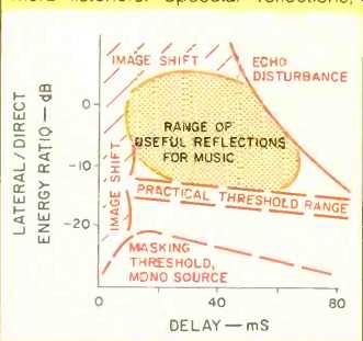
Fig. 1--The effect of delayed
The objective, then, is to eliminate common acoustical problems such as slap and flutter echoes, resonances, and frequency coloration, without creating the adverse acoustical side effect of a "dead" or lifeless-sounding space. In fact, we would like to psychoacoustically allow the openness and natural ambience of a larger space to be perceived in a physically smaller room.
The design of a critical listening room requires an appropriate balance among three acoustical ingredients absorption, reflection/diffusion, and room geometry In Fig. 2, the temporal (time) and spatial (angular) properties of the three basic surface types are shown.
An ideal absorptive surface absorbs all the sound striking it, over a wide range of frequencies (which is very important). Consequently, only the direct sound is observed in the temporal distribution plot. Since no sound is reflected, no polar plot is shown.
A reflective surface, whose proper ties are shown in the middle row of Fig. 2, scatters the incident sound in a specular direction, as a mirror would reflect light. Hence, the first and second intense spikes in the temporal distribution refer to the direct and reflected sound, respectively. The reflected sound's time of arrival is related to the difference between the direct distance from the source to the listening position and the total distance from the source to the reflecting surface to the listener.
The polar pattern for a reflective surface shows a peak in the direction of the reflection, which in this example is approximately 45° to the surface. In this discussion, we will refer to path-length differences in milliseconds or thousandths of a second. This can easily be translated into distance by recognizing that sound travels approximately 1.13 feet every millisecond. For example, the path-length difference between the direct sound from a loud speaker and a reflection from a back wall 10 feet behind the listener is 20 feet or 17.7 mS.
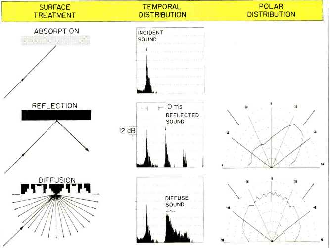
Fig. 2--Comparison of temporal (time) and spatial (polar) diffusing
properties of absorptive, reflective, and diffusive surfaces. The scattered
energy from an ideal absorptive surface (top row) is negligible; therefore,
no polar plot is depicted. The energy scattered from a reflective surface
(middle row) has minimal time spread and is reflected principally in
one direction for each direction of sound incidence. The diffusive surface
(bottom row) provides appreciable time spread and angular distribution
of the backscattered sound for all angles of incidence.
Now, let's briefly examine the effects of the listening environment on stereo imaging, frequency coloration, and envelopment.
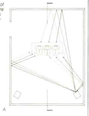
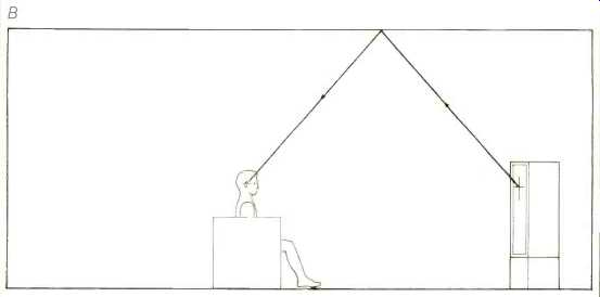
Fig. 3--Top (A) and side (B) views of a typical home listening room,
before treatment. Note the reflecting points on the side walls and ceiling,
which require treatment.
Stereo Imaging
The subjective dimensions of "sound space" can be described in terms of directionality of the source, definition, and spaciousness--the perception of distance or depth beyond that which can be inferred from the ratio of direct-to-indirect sound. Stereo imaging is sensitive to frequency-domain notches in the range from 1 to 18 kHz because these notches mimic the pinna and torso transfer functions caused by coherent reflections from the outer ear and upper body. Today it is possible to encode predetermined three-dimensional spatial paths or sonic illusions--e.g., Doug Jones' Listening Environment Diagnostic Recording (LEDR)-with vertical motion and depth perception cues, in addition to the much simpler and more familiar left-right panning effects of contemporary music. This spatial information can be captured during the performance or added afterwards with effect processors such as a "spatial reverberator" [5]. When auditioned over headphones these sonic images can be quite impressive. However, auditioned over loudspeakers, they can easily be completely corrupted by very early reflections in the listening environment. The frequency range of these very early reflections can easily be controlled by creating a diffusive or absorptive Reflection Free Zone.
An RFZ is simply a volume of space in which early reflections from nearby and speaker boundary surfaces are minimal, and the predominant sound source is the direct sound from the loudspeakers. Kirchhoff diffraction theory suggests that to minimize early reflected energy at a listening position there is an equation with at least three major variables to consider: The reflection function, which is 1 for a purely reflective surface and less for a diffusive or absorptive surface; the obliquity factor, which is a maximum for normal incidence and reflection, and the interference term, which is a maximum at a specular angle, where the angle of incidence equals the angle of reflection. Therefore, to minimize reflections at a listening position, we can make boundary surfaces diffusive or absorptive; alternatively, we can angle and splay speaker boundary surfaces so reflected energy can be directed away from the listening position.
A concept helpful to understanding and creating an RFZ is to picture the front speaker boundaries (walls, ceiling, floor) covered completely with mirrors. A person seated at any listening position should not be able to "see" a reflection of either speaker if he or she is within the RFZ.
Here is a simple technique to create an RFZ in your home listening room. It requires two people and a mirror. One person serves as an observer and the other positions the mirror along potential reflecting surfaces (walls, floor, and ceiling). The object is to identify specular positions which can be splayed, made diffusive, made absorptive, or all of the above. In a typical room with speakers in the corners and a sofa 10 feet away, the observer assumes a position at the left end of the sofa, and the attendant moves the mirror along the ceiling, walls, and floor at the front of the room. Wherever the observer can see a reflection of either speaker, the position of the mirror is marked. This process is repeated with the observer at the center of the sofa and at its far right. The RFZ that can be created by treating the room's surfaces at the marked positions will extend all along the sofa. Now, one has the option of splaying the room's surfaces, if the room can be modified, and/or placing absorption, diffusion, or Abffusion materials along those portions of the boundaries needing treatment. (Abffusion, a trademark of RPG Diffusor Systems, is a surface treatment simultaneously providing absorption and dif fusion.) If the room is very small (e.g., 10 by 15 by 8 feet), excessive absorption should not be used, because it will tend to make the room sound smaller.
Figure 3A shows locations on the side walls which require treatment, and Fig. 3B shows a location on the ceiling which needs treatment.
Frequency Coloration
In addition to image shifting, very early reflections cause frequency coloration when they are strong with respect to the direct sound. This is called the speaker-boundary interference response (SBIR). The primary effect of the SBIR is the creation of severe broad-band notches in the frequency response, especially at low frequencies, where absorptive/diffusive surface treatments are minimally effective.
Frequency coloration can be reduced by flush-mounting speakers in massive, properly splayed boundaries (as is done in critical recording control rooms). In home listening rooms, flush-mounting speakers and splaying walls are rarely done, for a variety of reasons. Positioning a speaker at different distances from the wall, ceiling, and floor can help, but one must still be aware of the coloration imposed by SBIR. To lessen the depth of the first frequency notch, one can position absorption or Abffusion materials in the corners behind the speakers. Again, beware! While absorption is certainly helpful in optimizing a listening position, it should not be used in excess.
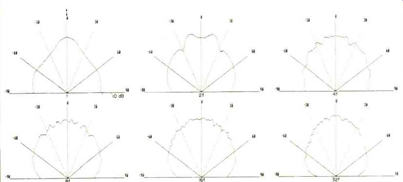
Fig. 4--Polar energy response from an RPG diffusor, showing uniform
scattering between -90° and +90° over five musical octaves from f = 250
Hz to 32f = 8,000 Hz.
Envelopment and the RPG Diffusor
Once we have configured the front of the room so that the predominant energy at all listening positions is the direct sound, we can turn our attention to the acoustical treatment of the sides and rear of the room. We would like the reflections from the room to add some ambience, creating the sensation that we are enveloped in the sound and participating in it, without corrupting the stereo imagery and causing frequency coloration. Psychoacoustic re searchers have examined this situation; they have determined that the in direct reflected sound in a room should be sequenced, arriving approximately 20 mS (or at least 10 mS) after the direct sound, and be temporally and spatially diffuse. Temporal diffusion refers to the distribution or density of reflections over time. Spatial diffusion refers to the polar or angular energy distribution. It is important to create a uniformly (or isotropically) dense reflection pattern so that, over a broad range of frequencies, no point in time or angular direction is favored.
This subjective diffuseness (or lack of directional impression) and the sensation of envelopment are created when the sound fields at each ear are dissimilar and poorly correlated. We perceive directionality instead of diffuseness when the sound reaching each ear is highly correlated over approximately 1 mS (roughly the time it takes for a sound to travel the distance between ears); strong, isolated reflections produce such correlated sound.
Many approaches have been used in the past to scatter sound-irregular geometrical surfaces, mono-cylindrical and poly-cylindrical columns, distributed absorption, etc. With the RPG acoustical diffusor, it is quite easy to create, in a small room, a diffuse sound field such as would be found in a larger room. The thin, 2-by-4-foot RPG diffusor consists of a periodic grouping of wells having equal width but different depths, separated by thin dividers. It is an acoustical analog of the diffraction grating used to scatter light for the past 100 years. The diffraction directions for each frequency are determined by the dimensions of each unit of the periodic grouping, and the intensity in any direction is determined by the depth sequence within a period.
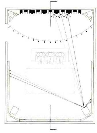
Fig. 5A--Top view of listening room, showing application of RPG diffusors
on rear wall, Abffusors behind speakers in front corners, Triffusors
in rear corners, and broad-band absorption (shaded areas) on front and
side walls. Uniform diffuse wavefront is indicated by dashed, curved
line behind listening position; dashed rectangle in front of listening
area represents location of ceiling treatment.
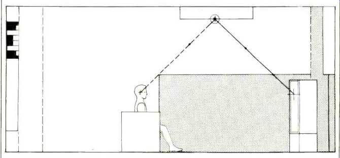
Fig. 5B-Side view of same room as in Fig. 5A, showing absorption on
side walls, vertical Abffusors from floor to ceiling in front corners,
and absorptive treatment on ceiling. For greater spaciousness, a diffusive
ceiling can be used, in which case upper side walls reflect laterally
diffused sound (dashed line with arrow) from ceiling diffusors.
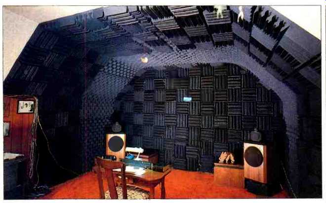
Fig. 6--The dead end of a Live End/ Dead End (LEDE) room in Pisha's home.
Front speakers are B & W 801 Fs and Janis WI subwoofers.
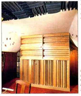
Fig. 7--The live end of the same LEDE room as in Fig. 6. Free-standing
wall of RPG diffusors measures 8 by 8 feet and is positioned 40 inches
from back wall.
The depths are based on a series of numbers produced by quadratic equations [6] which provide optimum phase variation, and result in an excellent diffusor. Sound striking these surfaces is scattered over time and uniformly over 180°, incorporating a broad range of frequencies. Figure 4 shows experimental polar patterns from an RPG diffusor; the patterns cover five musical octaves, from 250 Hz (labeled "f" in Fig. 4) to 8,000 Hz (labeled "32f").
The primary functions of RPG diffusion are to:
1. Provide a uniform high density of closely spaced reflections without density gradients or discontinuities;
2. Provide a dense pattern of uniformly distributed, irregularly spaced frequency notches;
3. Uniformly backscatter a broad frequency bandwidth over a wide angular range, and
4. Reduce backscattered energy, to minimize interference with the direct sound, frequency coloration, and image shifting.
Consider what you hear when listening to music in an auditorium. The first sound you hear from the stage is the direct, line-of-sight sound. The next sound you perceive is the indirect reflected energy from the closest boundary surface. This first significant reflection is separated in time from the direct sound and is not necessarily isolated, because there may be other reflection paths closely spaced in time. Because of the nature of the enclosed space, there is an initial time-delay gap between the direct sound and the first indirect reflected sound from the auditorium boundaries. Keep in mind the importance of this time gap in the perception of room size.
Can you create an appropriate initial time-delay gap in a small listening room? The answer is yes. And you are well on your way by having first established an RFZ in the front of the room.
The creation of an RFZ allows the indirect energy reflection pattern to be sequenced. That is, a time delay gap, related to the time it takes the sound to pass the listening position and return from the rear and rear-side surfaces, will be created, because the RFZ sup presses early reflections from the front of the room. However, a small room is dominated by isolated directional specular reflections and a lack of diffusion. By treating the rear and side walls with RPG diffusors, as shown in Figs. 5A and 5B, the energy passing the listening position is reintroduced after an ITD, temporally and spatially diffused.
In this manner, the combination of an RFZ and RPG diffusors permits the ac curate binaural perception of stereo images over a wide volume of space, minimizing frequency coloration and creating the spatial impression of being in a large space while in a physically small room.
Treatment of a Home Listening Room
We set out to establish an optimum listening environment in the home of coauthor Pisha. The room, which measured approximately 19 1/2 by 13 1/2 by 8 1/2 feet, was cleared of everything but the speaker system. Surface treatment was removed from walls and ceiling.
Speakers were arranged near two corners of the room, 10 feet apart, on 8-inch pedestals filled with sand. The listening position was placed equidistant from each speaker and 7.7 feet from the center line between the speakers.
An energy-time curve was taken with the Techron TEF System 10. Figure 8A represents the energy and arrival time of all reflections in the room, before treatment. Note the interfering ceiling, floor, and side-wall reflections and the sparse reflection pattern from the room.
Using the mirror technique de scribed earlier, interfering early-reflection surfaces on ceiling, floor, and side walls were identified for each listening position. These surfaces were then treated with Sound-Sorber foam panels, manufactured by Discrete Technology, to create an RFZ (Fig. 6). Since there was no intention to modify the existing walls or flush-mount the speakers, a triangular wedge of absorptive material was placed in each corner behind the speakers to improve the modal (resonant) response of the room.
Next, specular reflections from the rear surfaces were located. An array of RPG diffusors was positioned parallel to and 40 inches from the back wall, covering all specular surfaces. An area of 32 square feet was covered with lateral diffusive surfaces (vertical wells), and an equal area was covered with vertical diffusive surfaces (horizontal wells), forming a cluster measuring 8 by 8 feet (see Fig. 7). The energy-time curve results are shown in Fig. 8B.
Note the RFZ, the tremendous increase in density of the reflection pat tern from the room, and the exponentially decaying sound field. Aside from scale, the listening-room measurements compare favorably with those of a world-renowned concert hall, the Concertgebouw in Amsterdam (Fig. 9), and of a recording control room at Master Sound Astoria in New York City (Fig. 10).
We verified our sonic changes by auditioning a Telarc CD of Tchaikovsky's "1812 Overture," by playing an LEDR tape (manufactured and distributed by Electro Acoustic Systems Inc., 715 Monroe St., Evanston, Ill. 60202), and by making TEF measurements such as those of Figs. 8A and 8B. Playback equipment included a Mark Levinson ML-3 amplifier and ML-1 preamp, B & W 801F loudspeakers, a Janis Interphase 1A subwoofer amplifier, and Janis W1 subwoofers.
Listening experiments revealed precise and accurate stereo imaging at all listening positions in the room. Psychoacoustically, there was a sense of being immersed in the sound, in a much larger space more commensurate with the environment in which the sound was recorded.
Based upon the above data and our listening experience, we conclude that it is feasible to use the RFZ/RPG concept in small rooms such as those found in private dwellings.
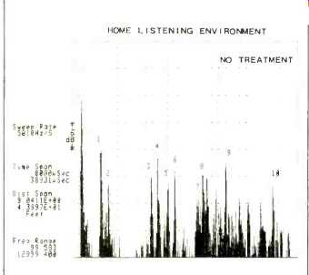
Fig. 8A--Energy-time curve of Pisha's listening room of Figs. 6 and 7,
before treatment. Interfering reflections include: (1) 11.7-mS floor
reflection between speaker and listening position, (2) 12.7-mS reflection
from ceiling between speaker and listening position, (3) 18.6-mS reflection
from multiple floor-ceiling paths, (4) 19.5 mS and (5) 21.1-mS reflections
from opposite side wall, (6) 21.9-mS multiple floor path, (7) 24.9-mS
rear-diagonal left reflection, (8) 25. 7-mS rear reflection, (9) 29.2-mS
rear-diagonal right reflection, and (10) 35.5-mS multiple-path reflection.
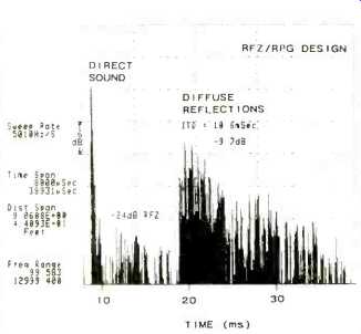
Fig. 8B--Energy-time curve of Pisha's listening room of Figs. 6 and
7 after RFZ/RPG treatment, showing much improved response. An initial
time-delay gap of 10 mS was created with an RFZ 24 dB below the direct
sound.
The reflection pattern consists of a dense, uniform, exponentially decaying sound field.
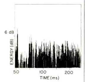
Fig. 9--Energy-time curve of the Concertgebouw concert hall in Amsterdam.
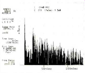
Fig. 10--Energy-time curve of RFZ/RPG control room at Master Sound Astoria.
References
1. D'Antonio, P., and J. H. Konnert, "The RFZ/RPG Approach to Control Room Monitoring," 76th Audio Engineering Society Convention, New York (October 1984), Preprint No. 2157.
2. Barron, M. F. R., "The Effects of Early Reflections on Subjective Acoustic Quality in Concert Halls," Ph.D. The sis, University of Southampton (1974).
3. Rodgers, C. A. P., "Pinna Trans formations and Sound Reproduction," Journal of the Audio Engineering Society (JAES), Vol. 29, No. 4 (April 1981), pgs. 226-234.
4. Haas, H., "The Influence of a Single Echo on the Audibility of Speech," JAES, Vol. 20, No. 2 (March 1972), pgs. 145-159.
5. Jones, Douglas R., William L. Martins, and Gary S. Kendall, "Optimizing Control Rooms for Stereo Imagery," Invited Paper D-1, 110th Meeting of the Acoustical Society of America, Journal of the Acoustical Society of America, Supplement 1, Vol. 78 (1985), pg. S9.
6. Schroeder, M. R., Number Theory in Science and Communication, with Applications in Cryptography, Physics, Digital Information and Self-Similarity, Springer, Berlin, 1986.
(adapted from Audio magazine, Sept. 1987)
Also see:
= = = =