Manufacturer's Specifications
Amplifier:
Rated Power: 100 watts into nominal 5-ohm load, 20 Hz to 20 kHz.
Rated Distortion: 1% at 100 watts.
Input Sensitivity (for Full Output): 775 mV.
Input Impedance: 137 kilohms.
Dimensions: 13 1/2 in. W x 6 1/2 in. H x 7 in. D (34.3 cm x 16.5 cm x 17.8 cm).
Weight: 35 lbs. (15.9 kg) each.
Price: $2,650 per pair.
Preamplifier:
Phono Input Impedance: MM version, 47 kilohms; MC version, 500 ohms.
Input Sensitivity (for Full Output): MM, 1 to 3 mV; MC, 0.33 to 1 mV.
Line Amplifier Gain: 8 (100 mV for 0.8 V).
Output Impedance: Low-impedance output, 600 ohms; high-impedance output, 10 kilohms; tape output, 100 kilohms.
Dimensions: 19 in. W x 3 in. H x 6 1/2 in. D (48.3 cm x 7.6 cm x 16.5 cm).
Weight: 10 lbs. (4.5 kg).
Prices: With moving-magnet phono input, $1,050; with moving-coil phono input, $1,350.
Company Address: 4774 Murietta St., Suite 9, Chino, Cal. 91710.
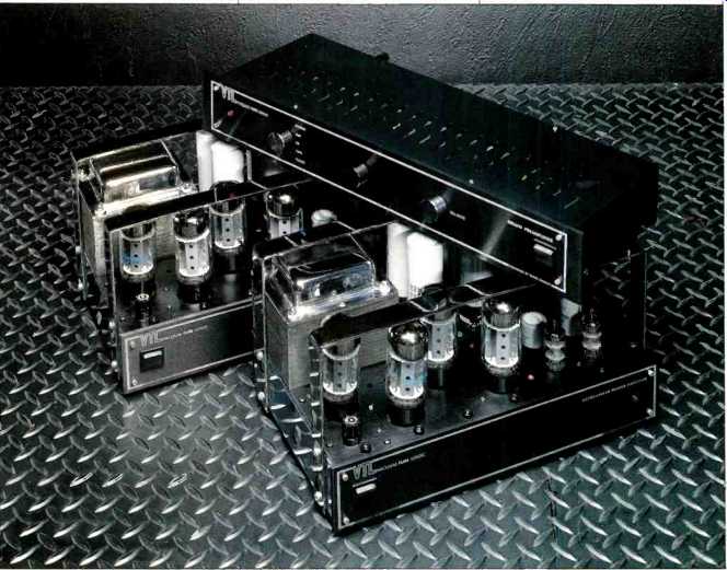
I have followed the progress and success of Vacuum Tube Logic, or VTL, with interest more or less since the company's inception. Their line seems to include an almost excessive number of models, especially power amplifiers; VTL says they want to make available a wide range of tube "flavors." The Compact 100 monoblock amplifiers and the Deluxe preamp reviewed here are at or just below the middle of VTL's product line and are competitively priced.
I have had some prior experience with VTL gear, and while I recall some reliability problems with at least one earlier model, I also remember the sound of these units as being very good. So it was with pleasure and anticipation that I agreed to review some of their equipment.
The VTL amps' power tubes, transformers, and filter capacitors appear to be mounted to the top surface of the chassis, as they were in old-time tube amps. In fact, however, the tubes, tube sockets, and the smaller filter capacitors are mounted to a p.c. board beneath and parallel to the top of the chassis. The main filter capacitors are longer than they appear to be, as they extend inside the chassis, and are mounted with standard capacitor clamps.
Chassis construction is simple: A chrome-plated piece is bent to form the amp's front subpanel and the sides, two pieces are used for the top surface of the chassis, and the rearward piece is bent over to form the rear panel. A front panel and bottom cover complete the enclosure. Two protective bars cover the tubes and transformers. VTL emphatically says that these bars are not for handles, but I'm sure that is what everybody uses them for; I know I do.
On the top, in front of the output tubes, are four tip jacks for measuring the individual plate currents of the output tubes. This is done as a voltage measurement in respect to ground, assessing the plate current as a voltage drop across 10-ohm cathode resistors. It would have been nice if there were a jack for ground as well. Behind the four output tubes are five access holes for adjusting the trimpots that control the individual plate currents and overall idling current. Another pair of tip jacks and a balance pot near the driver tube permit adjustment of the push-pull balance.
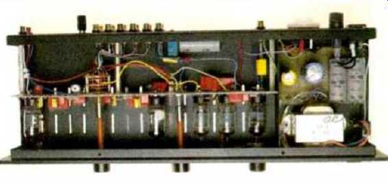
Underneath, the wiring and construction are reasonably neat, and parts of good quality are used. The p.c. board on my sample hadn't been cleaned of rosin from the soldering; I find this not as attractive and finished-looking as when the rosin is removed. A piece of VTL interconnect wire is used between the input signal jack and the p.c. board.
An LED pilot light and power on/off switch are all that is found on the amp's front panel. On the rear panel are a high-quality female RCA signal input jack; good gold-plated, five-way binding posts; the power cord, and a designation plate giving the model and serial numbers.
The Deluxe preamplifier is of the minimalist, straight-line school. It has inputs for phono and four high-level sources.
The unit reviewed had a phono stage whose gain was set for moving-magnet cartridges, but a moving-coil version is also available.
The controls on the preamp's front panel are, from left to right, a rotary input selector switch, rotary volume and balance controls, and a rocker-type power switch. A red LED at the left side of the panel indicates power on/off. On the rear panel are the signal input/output connectors, which appear to be Tiffany or Tiffany look-alikes, a binding post for ground connections, a three-pin socket for the line cord, the a.c. power fuse, and a TO-3 filament regulator protected by an appropriate insulating cover.
One unusual note is that the preamp has both low- and high-impedance line outputs. The high-impedance set is for driving an amplifier where the cable run is short. The low impedance outputs come from a cathode follower driven by the high-impedance output point .in the line amplifier.
Although this preamp doesn't have a tape monitor switch, one of its high-level input pairs is labeled for tape, and there is a tape-out jack pair for recording. Be careful with this arrangement, as it permits feedback between the tape output and input if "Tape" is selected as a signal source while the tape deck is recording Also, be sure to disconnect the tape recorder from the record output jack when the deck is off, because the input impedances of some tape decks become very nonlinear when their circuitry is not powered.
This possibly nonlinear tape recorder load could adversely affect the signal source selected for listening. Easy to miss, on the bottom of the unit near the right front corner, is a switch for setting line voltage to 120 or 240 V a.c.
Construction of the Deluxe preamp, like that of the power amps, is simple and straightforward. A main chassis piece is bent up into a U that forms the front subpanel, bottom, and rear panel. A separate front-panel piece and another U-shaped piece for the top cover complete the enclosure. The power supply, toward the right side of the unit, takes up approximately 25% of its internal volume. A vertical shield, oriented front to back, partitions off the power supply from the rest of the internal space. Within the power-supply area are the power transformer, a p.c. board that mounts the low and high-voltage rectifiers, dropping resistors, filter capacitors, and the panel-mounted power switch and line cord socket. The rest of the internal space is taken up by the signal circuitry. A vertical p.c. board runs from left to right, the full internal height of the preamp, and is spaced about halfway back from the front panel. This board contains most of the parts, including the five tubes, selector switch, and volume control. Shaft extensions couple the selector switch and volume control to the front-panel knobs. Noticeable to a critical observer is that when the volume control knob is pushed, the middle p.c. board flexes. Perhaps more support would be in order. The balance control is mounted from behind the front panel. Another p.c. board, situated just inside the rear panel, mounts the signal input and output connectors and a final B + decoupling capacitor.
Circuit Description
All of VTL's power amplifier circuits are basically like the ones shown in Figs. 1A, 1B, and 1C. (These Figures are reproduced, with the permission of VTL, from their neat little publication, The Vacuum Tube Logic Book, which shows all of their schematics and loads of other interesting stuff. I would recommend that anyone interested in tube circuitry get a copy of this book, which is available from VTL for $12 in the United States, $18 for overseas orders.) The various VTL models differ in the kind and number of their output tubes, the number of paralleled driver tube elements (the larger amplifiers have more than two output tubes per push-pull side), and the capacity and sophistication of their power supplies.
As can be seen in Fig. 1, the circuitry of VTL's amplifiers is very straightforward. A common-cathode input stage, composed of two tube elements in parallel, is capacitor-coupled to a long-tailed pair (or differential-amplifier), phase-inverter driver stage. The a.c. balance is controlled by varying the value of one of the plate load resistors. Most of the output stages of VTL amplifiers are configured for ultralinear operation, with screen taps on the primary of the output transformer. Also common to VTL's power amps is the relatively low plate current per output tube, 26 to 32 mA, that is set at the factory. Usually, tube power amplifiers have plate currents on the order of 55 to 70 mA per tube. VTL believes that, although these levels of current do indeed result in reduced measured distortion, the difference is not that audible and the reduction in tube life is not worth it.
Three full-wave diode bridges are used in the Compact 100 to provide the high-voltage, bias, and filament supplies.
The input tubes' heaters are run on d.c. for lowest hum. The Compact 100 has a single control to adjust overall bias, a relatively recent addition to VTL's amplifier designs that is not present in all models. This makes it possible to run up the bias by turning one control, instead of commutating among the four individual bias pots, if one wishes to run up the bias current for "better sound" (which the company emphatically does not recommend) and is willing to accept the consequent reduction in output-tube longevity.
The main high-voltage filter-capacitor arrangement in the Compact 100 consists of four 1,000-µF, 300-V units. These are connected in series-parallel for a composite rating of 1,000 µF and 600 V. Suitable resistors wired across the paralleled units serve as bleeders and equalize the voltage across all of the capacitors. This is quite a lot of energy storage, some 125 joules, and probably accounts for a good part of the solid, socko quality of the Compact 100's low end.
One smart thing that designer David Manley does is to make full use of all of the copper in the output transformer secondary windings. In contrast to the usual arrangement of multiple output taps, some of which are not used with loads of various impedances, VTL uses a four-section secondary that is connected at the factory in series-parallel as an optimum match for a 5-ohm load. This will drive most of the speakers around very nicely. If one has a really difficult low impedance load to drive, the dealer can connect the wires in parallel for a 1.25-ohm match.
Signal circuitry for the Deluxe preamp, like that of the power amps, is quite conventional; it reminds me of many preamp circuits of the '50s. The phono preamp section is a two-stage block, with feedback equalization to generate the RIAA response. Both tubes are connected in the common cathode configuration; the second-stage cathode is bypassed with a capacitor for maximum loop gain. The output of the phono preamp stage goes to one input of the selector switch. The wiper of the selector switch goes to the record out jack and into the top of the volume control. The volume control's output directly feeds the input of another two-stage amplifier. Connection of these two tubes is, again, a cascade of two common-cathode amplifiers.
A wideband, flat-feedback network from the second stage output back to the first-stage cathode includes the balance control's resistor elements. This arrangement varies the gain between the two channels of the output amplifier in a manner similar to that of a silvered conventional balance control. The output of this two-stage feedback pair is connected through a suitable coupling capacitor to the high impedance output jack. Calling this output "high impedance" is not strictly true, as negative feedback probably reduces the output impedance to a few thousand ohms.
Through another coupling capacitor, this point feeds the input of the cathode-follower stage. If the cable connecting the preamp to the system power amp is short, the high impedance output can be used without significant loss of highs and with the benefit of not going through another stage (the cathode follower). For longer cable runs or amplifiers with lower input impedances, the low-impedance output should be used.
Power-supply circuitry for the Deluxe preamp is quite simple and is without any fancy regulation except for the filament supply. The high-voltage secondary winding on the power transformer is rectified with a full-wave bridge and fed into a multi-section RC filter. A number of the filter capacitors have some 400 uF of capacitance. Final B+ to the circuitry is about 250 V, and it appears that no decoupling is used between the output amplifier and the phono stage. Regulation for the heater supply for all the tubes, after full-wave rectification and capacitor filtering, is provided by a 7812 regulator.
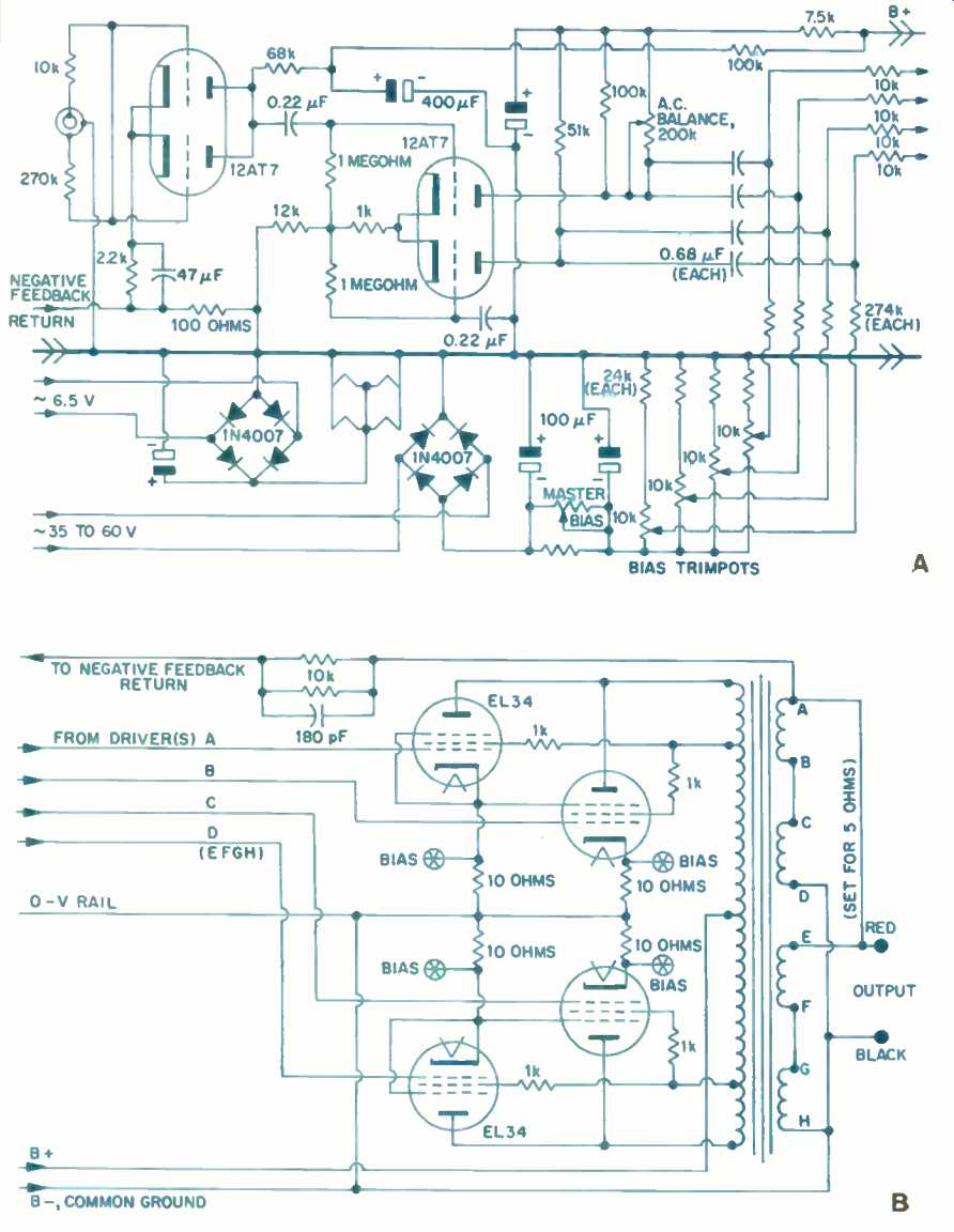
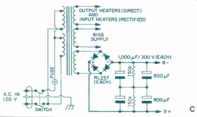
Fig. 1--Schematic diagram of VTL amplifiers' input and driver stage (A),
output stage (B), and power supply (C).
Measurements
Rather than referring to the left or right channel, which is not relevant to a pair of mono power amps, I will identify the two VTL units I tested by the last three digits of their serial numbers: 229 and 230. Voltage gain of both of the amplifiers was 36 x , or 31.3 dB, with 8-ohm loads. The IHF sensitivity was 80 mV for both units. Vacuum Tube Logic sets the gain of their power amplifiers, especially those of higher power, somewhat higher than the 26 dB typically seen in solid-state amplifiers. This gain is for some professional applications, where apparently full power output is desired to occur when the input level is 775 mV. This extra gain makes the amps easier to drive but can accentuate preamplifier line-amp noise. Such high gain is very nice in my situation, where I use no preamp line amplifier, and obviously would also be nice in other systems where a passive control center is used.
Total harmonic distortion plus noise is presented in Fig. 2 as a function of frequency, power, and loading. The data shown is for amp 229. Both of the units had similar distortion behavior, but amp 230 was noisier, having some subsonic noise that obscured distortion readings at low levels. With Bohm loading, it takes a higher output-transformer primary (and secondary) voltage to produce the 80 watts output that I show as the highest power in Fig. 2. The amplifier could not put out 80 watts into 8 ohms at 20 Hz, as its output transformer was saturating, with consequent bad waveform distortion. However, with 4-ohm loading, 80 watts at 20 Hz was attainable. I think the output transformer's core size is a bit too small for a 100-watt amplifier. Total harmonic distortion plus noise for a 1-kHz signal, and SMPTE-IM distortion, are shown in Fig. 3 as functions of power output and of loading.
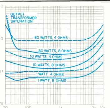
Fig. 2--THD + N of Compact 100 as a function of frequency and power output
for 8- and 4-ohm loads; see text.
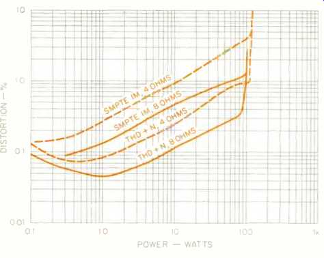
Fig. 3--SMPTE IM and THD + N vs. power and load. THD + N is for a-kHz signal.
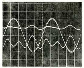
Fig. 4-Distortion residues and the original 1-kHz signal. For 10 watts into
8 ohms (top E trace), distortion was 0.14%; for 20 watts into 4 ohms (bottom
trace), distortion was 0.4%.
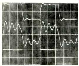
Fig. 5-Amplifier square wave response.' Top trace is 10 kHz with 8-ohm load,
middle trace is 10 kHz with 2-µF capacitance across the 8-ohm load, and
bottom trace is 40 Hz into 8 ohms. (Scales: Vertical, 5 V/div.; horizontal,
20 µS/div. for 10 kHz, 5 mS/div. for 40 Hz.)
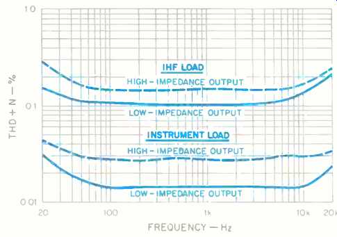
Fig. 6-THD + N vs. frequency of Deluxe preamp's line section.
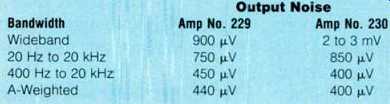
Table 1--Output noise of VTL Compact 100 monoblock amplifiers with a source
impedance of 1 kilohm. The IHF S/N ratios, with the same source impedance,
were 76.5 dB for amplifier No. 229 and 77.0 dB for amplifier No. 230. The
high wideband noise reading for Amp No. 230 was due to low--frequency surges.
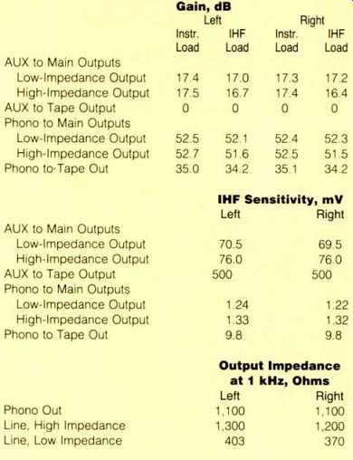
Table 2--Gain, IHF sensitivity, and approximate output impedances for VTL
Deluxe preamp. Note: Output impedance at tape out is the same as that of
the signal source. The output impedance of the phono section, measured
at tape out, was 1,100 ohms in either channel.
The distortion is generally low order (second and third harmonics) at low to medium levels, and some higher order odd harmonics come in at higher power levels with 8-ohm loading. With 4-ohm loading, the higher order odd harmonics come in sooner and have greater magnitude. Figure 4 shows distortion residues for a 1-kHz tone at 10 watts into 8 ohms and 20 watts into 4 ohms. Distortion is 0.14% in the 8 ohm case (top residual trace) and 0.4% for the 4-ohm load (bottom residual trace). Damping factor as a function of frequency was virtually the same for both amplifiers-about 15.7 over most of the audio range, falling off slightly at the extremes of 20 Hz and 20 kHz to about 14.8. Magnitude of output impedance was about 0.5 ohm, which is within the typical range for tube power amplifiers. Noteworthy was the relatively constant impedance over the audio range.
Rise- and fall-times at 10 V peak-to-peak amplitude were about 4µS with 4-ohm loading and 3.7 µS with 8-ohm loading. At the 1-watt level, frequency response above the audio range varied somewhat with loading; this is usual with most power amplifiers. Low-frequency response was essentially flat down to 10 Hz. High-frequency response was flat out past 20 kHz, peaking slightly at about 60 kHz and rolling off some 6 to 8 dB at 100 kHz. The peaking at about 60 kHz was +0.5 and +0.1 dB for 4and 8-ohm loading, respectively. Related to frequency response is square-wave response, some of which is displayed in Fig. 5. The top trace is for 10 kHz into an 8-ohm load at an output level of 10 V peak to peak. Some ringing is evident, and it isn't quite second-order damping (i.e., simple resonance). Investigation of frequency response beyond 100 kHz would no doubt show some multiple resonances. In the middle trace, an extra 2-µF capacitive load was placed in parallel with the 8 ohm resistive load. Here, ringing is quite strong at an approximate frequency of 60 kHz, right where the response with resistive loading peaks slightly. A frequency of 40 Hz was used for the bottom trace, which exhibits an excellent, extended low-frequency response.
If one takes a flat 100 watts as the rated power of these amplifiers, then clipping headroom comes out to-0.6 and +0.09 dB for 8and 4-ohm loads, respectively. Dynamic headroom was-0.44 and +0.5 dB for the same loading.
With the tone-burst signal used for tests of dynamic headroom, a 1-ohm load could be driven to about ±11 V, producing the same amount of peak current, ± 11 amperes.
Amplifier output noise for various bandwidths is shown in Table I. The high reading of 2 to 3 mV for the wideband measurement of amp 230, which prevented accurate low-level distortion readings, was caused by a noisy tube.
Line draw at idle and at 120 V was about 1.2 amperes. Full power at visual onset of clipping drew 2.2 amperes for 80 watts into 8 ohms and 3.2 amperes for 102 watts into 4 ohm loads. I also checked bias current uniformity by checking the voltage drop across the tubes' cathode-sampling resistors. With a good warm-up, amplifier 229 had plate currents of 30.1, 30.3, 30.4, and 30.9 mA for its four output tubes, while the plate currents of amp 230's four tubes were 28.6, 28.9, 30.0, and 30.5 mA. This is pretty good uniformity.
Power-supply regulation was also pretty good for a capacitive input filter system. The B + at turn-on, before the tubes warmed up and started to conduct, was about 520 V. At idle, B+ was 50 V; at 100 watts into 4 ohms, it had dropped to 470 V. The Deluxe preamplifier's gain and sensitivity measurements appear in Table II. Also shown in this Table are the approximate impedances of the various outputs.
Concentrating on the line section of the preamplifier first, THD + N was measured as a function of frequency, level, loading, and output (low or high impedance). Figure 6 shows THD + N for 1 V output. Loading either output with the 10 kilohms of the IHF load increases the distortion to about the same degree. This won't be a problem with any of VTL's power amplifiers because of their high input sensitivity and impedance. Measurements at higher output voltages with IHF loading yielded distortion levels somewhat higher than shown in the Figure, especially at the frequency extremes. The distortion behavior at the higher output voltages with instrument loading was much better and quite acceptable--in fact, either output could put out more than 20 V rms above 50 or 100 Hz.
Some specific information about the preamp's line-out low-frequency response appears in Table III. Since the 10kilohm loading rolls off the low-frequency response too much, in my opinion, I would recommend that the Deluxe preamp not be used with amp input impedances lower than 47 kilohms.
Rise- and fall-times for the line amplifier at its two outputs was checked at two signal levels, 2 and 5 V peak to peak. At the lower level, rise- and fall-times were both about 0.6 µS for the low-impedance output and about 1 uS for the high impedance output. The use of IHF loading increased the response times to 2.5 or 3µS for the high-impedance out and to 1 or 2 uS for the low-impedance out. At the output level of 2 V peak to peak, and with IHF loading, one can see the beginnings of slewing occurring in the negative-going direction for the low-impedance output and in the positive going direction for the high-impedance output. This shows up as longer response times in the aforementioned directions. With the volume control turned down 6 dB below maximum, rise-and-fall times were about the same as at maximum, although the edge shape developed more overshoot. At 5 V peak to peak, rise-and-fall times increased slightly with instrument loading. With IHF loading, stewing was evident on both outputs in the direction of tube cutoff-negative-going for the low-impedance output, which is fed by a cathode follower, and positive-going for the high impedance output, which is fed by a common-cathode amplifier. Slew rate was on the order of 1 to 2 V/µS. Square-wave responses for the output amplifier are shown in Fig. 7. The output level for all traces is about 2 V peak to peak. The top trace is for 20 kHz, taken at the low impedance output, with instrument and IHF loads. (Instrument load is 91 kilohms paralleled with about 200 pF; IHF load is 10 kilohms paralleled with 1,000 pF). Response at the high-impedance output is shown in the middle trace.
Low-frequency response and the effect of loading can be seen in the bottom trace, a 40-Hz square wave. The 40-Hz traces shown are for the high-impedance output; behavior of the low-impedance output was about the same.
Volume control tracking between channels was found to be within 0.6 dB at all levels down to -55 dB, increasing to a difference of 1 dB down to a level of -65 dB and to a 3 dB difference at 70 dB. When the balance control is turned toward either channel, that channel's gain is unaffected and the opposite channel's gain is attenuated up to a maximum of 8.5 dB.
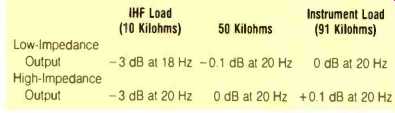
Table III-Low-frequency response limits of Deluxe pre-amplifier's line output
as a function of load.
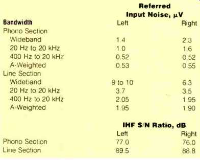
Table IV-Noise of Deluxe preamp, referred to input, with 1-kilohm input
termination, and IHF S/N ratio. Measurements were taken at the low-impedance
output. For the phono section's S/N measurements, the input was terminated
by an IHF dummy MM load.
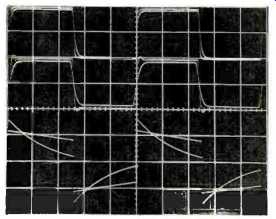
Fig. 7--Preamp's response to square waves through line inputs for, top to
bottom, 20 kHz through low-impedance output, 20 kHz through high-impedance
output, and 40 Hz through high impedance output. In each case, responses
with instrument and IHF loads are superimposed.
(Scales: Vertical, 1 V/div.; horizontal, 10 µS/div. for 20 kHz, 5 mS/div. for 40 Hz.)
Interchannel crosstalk, with the undriven input terminated in 1 kilohm, was measured and found to be asymmetrical in the two directions. In the worse (left-to-right) direction, overall crosstalk was greater than 80 dB down, from about 20 Hz to 1 kHz. At 10 Hz, the crosstalk came up a bit, to 75 dB. Above 1 kHz, it increased to 70 dB at 3 kHz, to 62.5 dB at 7 kHz, and to-53.5 dB at 20 kHz. Moving the balance control over its range didn't make the high-frequency crosstalk get worse, but turning down the volume control 6 dB from maximum increased the crosstalk quite a bit, to about -30 dB at 20 kHz in the worse (right-to-left) direction. Crosstalk in the line amp was in phase.
Referred input noise, along with IHF signal-to-noise ratio, is presented in Table IV for the line section as well as for the phono section. The tabulated results are for the low-impedance outputs, which were slightly noisier.
The phono section's RIAA equalization error is shown in Fig. 8 for several conditions. Note that the vertical scale is coarser than I usually use (2 dB per major division versus 1 dB per division). The middle curve is the equalization error at the tape out jacks with my normal instrument loading in parallel with the input impedance of my chart recorder. This makes for a combined load of about 32 kilohms, which is getting on the low side of desirable for tube equipment, but it is an impedance that one might easily find at the input of modern tape recorders. At 20 Hz, response is down about 4 dB, which in my opinion is too much. The top curve gives a better idea of the actual phono equalization error since the only load on the output of the phono preamp was then the volume control. This would represent the response when listening to records, providing the loading on the output of the preamp is high enough (see the discussion of line amplifier low-frequency response, above). The bottom curve is for an IHF load in parallel with my chart recorder input, or about 8.33 kilohms, which is ridiculously low loading for tube gear, and the resultant low-frequency roll-off is completely unacceptable. Forget about taping records with this preamp, or get a recorder with an input impedance of 50 kilohms (or, preferably, higher). On the good side is the excellent uniformity of response between the left and right channels.
Figure 9 shows the phono section's response to pre equalized square waves, measured at the tape output. Both instrument and IHF loads were used, and the waveforms showing the effects of each are overlaid; the traces with IHF loading have the lower amplitudes. The output level in the Figure is about 200 mV peak to peak. Some asymmetry can be seen at this level with the IHF loading on the 1and 10 kHz waveforms. The bottom trace, for 40 Hz, indirectly shows the phono preamp's low-frequency response (which is detailed in Table III); note that IHF loading causes severe differentiation of the square wave.
The phono section's harmonic distortion was measured for a number of conditions. At 1 V out, distortion was about 0.1% in the midband and increased to 0.4% at 20 Hz and to 0.65% at 20 kHz. IHF loading increased distortion at 1 kHz to 1.6%. My lab notes say, "Forget IHF loading of the phono preamp!" Phono overload versus frequency is presented in Table V. As can be seen, input signal acceptance tends to level off above 3 to 5 kHz. This is probably due to the relatively high value of the plate load resistor in the phono circuit's second stage and the circuit's attendant inability to drive the RIAA feedback network at higher frequencies.
Related to phono overload with sine waves is the behavior of a phono preamp with increasing input levels of a pre equalized, 1-kHz square wave. Figure 10 shows how the Deluxe phono preamp handles this admittedly difficult test. The way the waveform becomes asymmetrical is typical of many preamps, tube and solid-state alike. What I would consider a weakness in this circuit is the relatively low output level at which visible aberration occurs-on the order of 200 to 300 mV peak to peak.
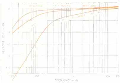
Fig. 8--RIAA equalization error for various output and load conditions;
see text. Modified instrument load is 32 kilohms; modified IHF load is about
8.3 kilohms. The two channels' responses matched so closely that they could
not be drawn as separate curves.
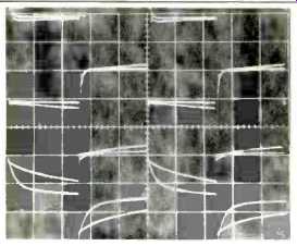
Fig. 9-Response of phono section to pre equalized square waves for 10 kHz,
(top), 1 kHz (middle), and 40 Hz (bottom), all obtained via tape output.
Both instrument and IHF loads were used and the results superimposed. (Scales:
Vertical, 0.1 V/div.; horizontal, 20 µS/div. for 10 kHz, 200 µS/div. for
1 kHz, and 5 mS/div. for 40 Hz.)
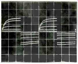
Fig. 10--Overload test of phono circuit, using pre equalized, 1-kHz square
waves at increasing input levels. (Scales: Vertical, 0.5 V/div.; horizontal,
200 µS/div.)
Table V--Phono overload vs. frequency, for MM input, with instrument loading.
Crosstalk in the phono stage was quite symmetrical in both directions when the input of the undriven channel was terminated in a 1-kilohm resistor but became somewhat less so when the input termination was the IHF dummy moving magnet load. In the worse (left-to-right) direction, crosstalk that was a constant 75 dB between 1 and 20 kHz with the 1-kilohm termination increased to 71 dB at 1 kHz, to 54 dB at 5 kHz, to -45 dB a1 10 kHz (where the dummy load resonates), and to -52 dB at 20 kHz. In the better (right-to-left) direction, the 10-kHz value was -64 dB. Crosstalk in the phono section was in phase.
From a measurement point of view, the power amps' strengths include wide bandwidth, low distortion order (at lower power levels, where most information resides), low power consumption (resulting in long life for the output tubes), essentially constant output impedance with frequency, and large energy storage in the power supply. Not as good as some competing designs are what might be considered a slightly undersized output transformer, relatively high measured distortion at higher power levels, a relatively high output impedance, and more than usual high-frequency ringing with capacitive loads. The preamp has good high-frequency bandwidth and adequate low-frequency response when loaded with VTL power amps. Loss of "weight" in the very low frequencies is likely to be the consequence of loading either tape or main outputs with less than 50 kilohms.
Use and Listening Tests
Equipment used to evaluate the VTL components included, as signal sources, an Oracle turntable fitted with a Well Tempered arm and Spectral Audio MCR-1 Select cartridge, a Magnavox 560 CD player feeding into a Wadia 2000 decoding computer, a Nakamichi 250 cassette player, and a Technics 1500 open-reel recorder. Other preamps used were my Cook/King reference phono-preamp/selector switch/stepped-attenuator unit and an Illusion No. 8 tube unit from Finland. A Head TX4 MC step-up transformer (from Esoteric Audio Research in Britain) was used with the VTL and the Cook/King phono preamps. Other power amps used were VTL 120s, a Counterpoint SA-20, and the EAR 519 100-watt mono tube Units that I use for reference. Most of the listening was done on Siefert Research Magnum Ill speakers. Some of the listening was done with some new Martin-Logan Monolith Ill speakers, using the Counterpoint amp for the cone woofer and the various tube amps to drive the electrostatic part of the Monoliths.
The Compact 100 power amps have good tonal balance with excellent bass quality. Compared to some amps I like, including my reference EAR 519s, the 100s are a little on the bright side with both the Sieferts and Martin-Logans. Revelation of detail is very good, as are space and depth. These amps have plenty of apparent power and can play most of the music I like bit louder than I usually want to play it.
The Deluxe preamp is a smooth-sounding unit. Tonal balance is reasonably neutral. Revelation of detail is good, although spatial depth is not as good as that of other units I have on hand or have previously reviewed. What is nice is that the music generally comes through with low amounts of irritation.
The preamp and power amps complement each other, especially with records, yielding a good tonal balance. I did feel that playing some of my musically favorite CDs through the combination sounded as if some detail and definition had been lost and that some irritation had crept in. However, many other CDs sounded stunningly musical and realistic. Most of the time, I was happily listening away to the combination and think that many people would be quite pleased with either or both of these VTL pieces.
The Compact 100 power amps operated without a glitch. The preamp had a mild switching transient when going to and from phono. It also had some r.f. sensitivity. In phono mode, I heard a radio station playing faintly-something that I had never heard in my setup before. Because of the power amplifiers' high gain, I could hear a faint hiss right at the speakers, probably the amplified input noise of the preamp's line amplifier or a combination of the line section's output noise and the power amplifiers' own input noise. This could be more audible with high-efficiency speakers.
Criticisms and nit-picking aside, these VTL pieces are quite musical and are very likely to satisfy the musical sensibilities of many of you out there. I recommend an audition.
-Bascom H. King
(Source: Audio magazine, Aug. 1990)
Also see:
Vacuum Tube Logic (VTL) Straight-Line D/A Converter (Nov. 1992)
= = = =