The Limited Model 2 preamplifier is one of several components designed by some
of the audio industry's top designers for Acoustic Research, a company best
known for its pioneering development of acoustic-suspension speakers. An interesting
discourse on the AR Limited engineering philosophy in the excellent and informative
owner's manual states: "It has long been recognized that hi-fi systems,
even the very best, are some what lacking when compared to live music." Despite
improvements in source material, loudspeakers, and electronics, "Live
music still reigns, and audio systems are still second." (I'll drink to
that!) Although the Limited series designs were optimized to play music, AR
admits that they do have some slight personality but feels that it isn't imposed
on the music.
In the numerous areas still open to audio designers, AR focused the development of the Limited series on two major points:
Signal equalization (which is handled in a very nice Limited series equalizer, the Model 6) and signal transmission. In order to optimize signal transmission, the Limited series' engineers decided that balanced operation was to be used wherever possible. Accordingly, the Model 2 is basically a balanced design, from input to output. Two balanced and three unbalanced inputs are provided, but the unbalanced inputs are converted to balanced by an input opamp. Each unbalanced input circuit's gain can be adjusted in three steps by moving jumpers on the main board, yielding overall gain of 0, +6, or +14 dB.
This feature helps to equalize the output levels of various unbalanced sources. With the balanced inputs, the overall gain is fixed at about 0 dB.
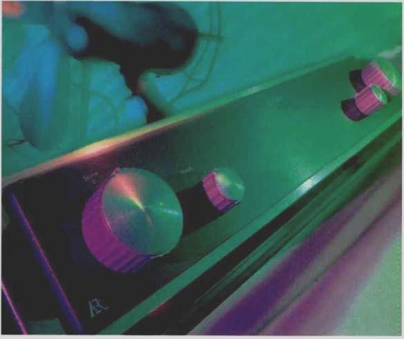
The four front-panel rotary controls are arranged in two pairs, one pair at the left of the front panel and the other at the right.
The functions of these knobs, from left to right, are signal selection, output polarity and muting, balance, and volume. A small red LED at the top center of the panel tells when power is on. On the rear panel are the signal input and output connectors, a ground post, an IEC a.c. power-cord socket, and the a.c. power switch.
===========
SPECS
Gain: Balanced main input to line output, 0 dB; single-ended main input to line output (variable), 20 dB max.
Input Impedance: Balanced, 24 kilohms; single-ended, 50 kilohms.
Output Impedance: Balanced, 100 ohms; main single-ended, 50 ohms; tape, 1 kilohm.
Maximum Input and Output: Balanced, 20 V rms; single-ended, 10 V rms.
THD and IM Distortion at Rated Output: 0.002%.
S/N: 110 dB, A-weighted, re: 1 V.
Slew Rate: 20 V/µS.
Dimensions: 19 in. W x 4 in. H x 13 in. D (48.3 cm x 10.2 cm x 33 cm).
Weight: 15 lbs. (6.8 kg).
Price: $2,200.
Company Address: 535 Getty Court. Bldg. A, Benicia, Cal. 94510.
===========
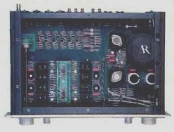
Within the Model 2, a large p.c. board takes up the whole internal area. All components-except the four-gang output-level attenuator, the a.c. power switch, and the RCA unbalanced input/output connectors-are mounted on the p.c. board. Power-supply components occupy about one third of the board area, with the remainder devoted to signal circuitry. High-quality parts are in abundant evidence here, and the build quality of this preamp is first rate.
Circuit Description
I was unable to obtain a schematic diagram of the Model 2 from AR, so the following is not as complete as I would normally report.
Unbalanced inputs are converted to balanced by two PMI OP275 dual opamps per input pair. With all input signals in high-level balanced form, they are then fed to the input selector. This is a four-section, fully enclosed, and environment-proof switch with silver-plated brass contacts.
The selected input is routed to the polarity/muting switch and also to the tape-out buffer. (Another OP275, along with a pair of discrete TO-5 transistors as output devices, is used for each channel's tape output). Signal out of the polarity/muting switch is passed on to the balance and volume controls. The volume-control attenuator in the Model 2 is something to drool over. It consists of a four-deck, 59-position switch.
Each deck is a p.c. board, with Dale miniature metal-film attenuator resistors mounted on it. Each attenuator divider point is picked up by a wiper contact that is, in turn, connected to a circular track that takes the attenuated signal out to the wiper terminal of the deck. An elegant detent mechanism completes the picture. These attenuators look very much like my memory of units used in the Cello Audio Palette, a totally beautiful piece of gear if there ever was one. I would surely like to have a couple of these attenuators to put in some of my own preamp designs! Output amplifier circuitry consists of four unity-gain buffers that present high impedance to the output of the volume-control sections and present low impedance and current-driving ability to the main signal outputs. A number of TO-5 metal-can discrete transistors, along with a complementary pair of TO-220 output transistors mounted on heat-sinks, are used in each of the four output sections. In my opinion, a topological flaw exists in the Model 2's unbalanced output:
The two input phases of a channel are not combined, as they would be in an amplifier with differential in puts and outputs; instead, each phase is passed straight on to the corresponding output phase. This means that both phases of a balanced input are not represented in each output phase. This matters because some signal sources (such as the Sonic Frontiers SFD-2 hybrid D/A converter, which I have heard but not reviewed) deliver better sound from their balanced outputs than from their unbalanced output.
Power-supply circuitry starts out with a generously sized toroidal transformer feeding full-wave-rectified secondary output into a pair of 8,200-g, 44 V filter capacitors. A pair of high-current integrated-circuit regulators are used in an unusual configuration that employs an external low-noise reference voltage. Four power-supply isolation buffers follow the main voltage regulators. One pair supplies the single-ended input stages; the other pair supplies the four active output-stage circuits. Final delivered supply to the circuitry is +15 and-15 V.
Measurements
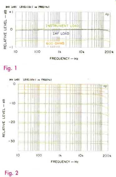
Fig. 1-Frecuency response.
Fig. 2-Frequency response will various volume-control settings.
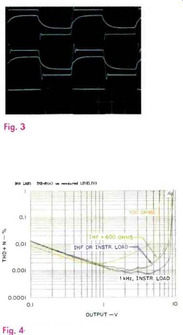
Fig. 3-Square-wave responses for 100 1(1-13 with output polarity at zero
(top and at 180 (middle), and for 20 Hz (bottom).
Fig. 4-THD + N vs. level and load. All curves are for 20 kHz except where noted.
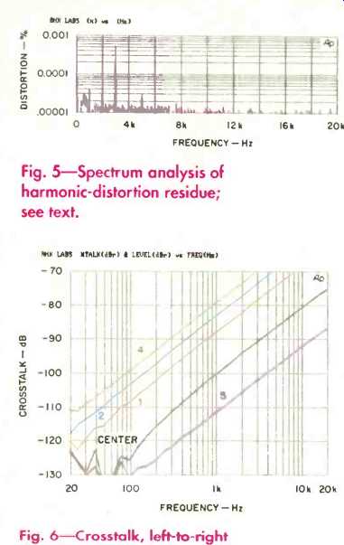
Fig. 5-Spectrum analysis of harmonic-distortion residue; see text.
Fig. 6-Crosstalk, left-to-right direction, for various settings of balance control.
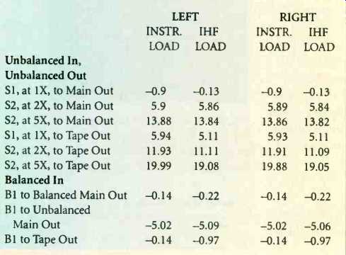
TABLE I--Gain, in dB, with various inputs (S1, S2, and B1).
Gain and sensitivity data for the Model 2 is enumerated in Tables I and II, respectively.
Frequency response with unbalanced input and output is shown in Fig. 1 for instrument, IHF, and 600-ohm loads. Data shown is for S2 (single-ended input 2) configured for +14 dB gain. Output level was set at maximum. Response in the unbalanced mode was essentially the same for the three input-amplifier gain settings. Further, response in the balanced-in and balanced-out mode was essentially like that shown in Fig. 1, except that the output drop with IHF and 600-ohm loads was twice as great because the balanced outputs' impedance is twice as high.
High-frequency response does vary with the setting of the volume control, as shown in Fig. 2 for un balanced input/output. Worst-case roll-off looks to be about-2.5 dB at 200 kHz.
Square-wave response for unbalanced input and output in the left channel is shown in Fig. 3. As can be seen, this output amplifier is fast.
The top and middle traces are for 100 kHz, and the bottom trace is for 20 Hz. The top trace is with output polarity set to "0°," and the middle trace was made at "180°". The faster, larger traces are for volume at maximum; the smaller, slower traces are with volume attenuated 6 dB. Results shown are for my instrument load; IHF loading didn't change much except to reduce the over- shoot slightly. Slewing can be seen in the photo. At the higher output level, 10 V peak to peak, three edges are slewing at about 26 V/µS, and the positive-going edge for the "0°" polarity setting is slewing at a faster rate of 50 V/µS. At the reduced level, 2.5 V peak to peak, rise-and fall-times are close to 100 nS for the "0°" setting and more like 120 nS for "180°".
Total harmonic distortion versus output level for a number of frequencies and load conditions is shown in Fig. 4. These conditions are: 1 kHz with instrument load and 20 kHz with instrument or IHF load (the two curves are identical), with the IHF load paralleled with 600 ohms, and finally, with a 100-ohm load. I'd say the Model 2 would drive about anything!
A spectrum of harmonic-distortion residue for a 1-kHz signal at 5 V out with unbalanced input/output, IHF load, and +14 dB gain is shown in Fig. 5.
I noticed in my pushing and poking about that the tape output buffers would oscillate on the positive peaks when driven to clipping. This also occurred with the in put amplifiers when they were driven into clipping. Since the op-amps are the same for both functions, this would seem to be an attribute of the op-amps and/or the particular way they are used in the AR Limited Model 2.
Crosstalk between channels was measured in both balanced and unbalanced modes. In all measurements, the crosstalk was essentially a rising 6-dB/octave function, indicating capacitive coupling between the channels. Figure 6 shows the crosstalk in the poorer (left-to-right) direction, using the unbalanced output and un balanced input Si configured for unity gain, and with volume at maximum. The numbers on the curves indicate the balance control's setting as the number of clicks to the right of center. As can be seen, all of the control's positions to the right of center degrade the crosstalk except for the one at the extreme right ("5"), which infinitely attenuates output from the left channel. Results in the right-to-left direction were some 5 to 8 dB better than those in Fig. 6.
Results in the balanced mode were similar to those shown for unbalanced signals.
Output noise for unbalanced and balanced modes, and the three unbalanced input-amplifier gains (1X, 2X, and 5X), are listed in Table III. As can be seen, the Mod el 2 has very low output noise and will likely have inaudible hum and hiss, even with high-gain power amplifiers and horn speaker systems. The IHF signal-to-noise ratios are listed in Table IV.
A few final measurements: The a.c. power-line draw was about 220 mA. Output impedance at the unbalanced outputs was about 43 ohms and was double that at the balanced XLR outputs. Input impedance for the balanced inputs was about 35 kilohms with volume at maximum and 38 kilohms with the volume set for about -20 dB. Input impedance for unbalanced in puts was about 50 kilohms and was constant with volume-control setting.
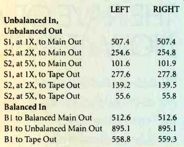
TABLE II-Sensitivity, in mV, with various inputs (S1, S2, and B1), for IHF
load.
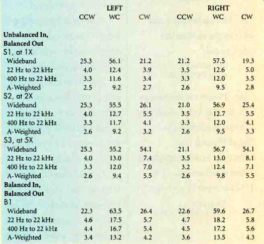
TABLE III-Output noise levels, in µV, with various inputs (S1, S2, S3, and
B1) volume-control positions (counterclockwise, worst case, and clockwise),
and bandwidths.
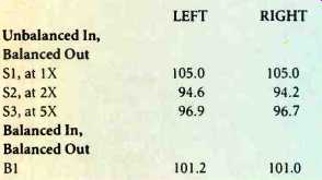
TABLE IV-- IHF S/N, in dB, with various inputs (S1, S2, S3, and B1), for
worst-case position of volume-control.
Use and Listening Tests
Equipment in my system during the re view period included an Oracle turntable fitted with a Well Tempered Arm and Spectral Audio MCR-1 Select moving-coil pick up used with a Vendetta Research SCP-2C pre-preamp. Krell MD-10 and PS Audio Lambda CD transports fed Sonic Frontiers' SFD-2, Sentec's DiAna, and other (experimental) D/A converters. Other signal sources included a Nakamichi ST-7 tuner, a Nakamichi 250 cassette deck, and a Technics 1500 open-reel recorder. Preamplifiers used included a Forssell line driver, a First Sound Reference II, and a unit from Quicksilver Audio-as well as no preamplifier at all. Power amplifiers on hand were a Crown Macro Reference and a pair of Quicksilver M135s. Loudspeakers used were B & W 801 Matrix Series 3s augmented with a Klipsch SW15 powered subwoofer.
As is frequently the case when I receive a new piece of gear, I loaned the Model 2 to a friend to try out for a while and get some hours on the unit. He reported favorably on the Limited Model 2's build quality and sound.
When I started formally evaluating the sonics of the Model 2, I had been using the excellent Sonic Frontiers SFD-2 D/A converter feeding balanced outputs into a Forssell tube line-stage preamp modified to have balanced inputs. This combination, driving either my Quicksilver M135s or the Crown Macro Reference, had been delivering extremely good sound with CDs. Best sound from the SFD-2 definitely comes from the balanced outputs, so when I started evaluating the Model 2, I used the balanced inputs for the SFD-2. Because I had determined during measurements that the Model 2 does not combine both input phases of a balanced input into the unbalanced outputs, I coupled the balanced outputs into the Macro Reference, with its inputs configured for balanced. Wow! This combination sounded exceedingly good. Definition and detail were of a high order, soundstaging was excellent, and there was an overall sense of musical believability. Although bass quality and definition were very good, bass extension and impact were not quite as good as when using the Forssell line unit driving the Crown in unbalanced input mode. All in all, the Model 2 is an excellent sonic performer. Operation was flawless, and there were no unexpected noises.
I do have a few nits, however. First is the aforementioned lack of differential-amplifier action in the output amplifier. Second, in this sample, the otherwise incredible volume attenuator had more rotary-shaft backlash in the middle of its rotation than at the ends.
In conclusion, the AR Limited Model 2 line preamp is a clear winner. Do go out and audition this one.
-Bascom H. King
( Audio magazine, Aug. 1994)
Also see:
Acoustic Research Turntable (July 1984)
Acoustic Research 338 Speaker (Nov. 1995)
Acoustic Research AR98LS Speaker (Equip. Profile, Jan. 1985)
Acurus L10 Line Preamp (Sept. 1992)
= = = =