by Neal Rayborn [1. *Consumer Plant Manager, Memorex Corporation* ]
THERE HAS been significant technological advancement and improvement in cassettes and cassette machines over the past several years. The interface between the cassette and machine, however, is an area that has received very little attention or discussion--yet this interface is critical to the successful functioning of the system.
The secret to successful interface is mechanical alignment, in addition to the usual azimuth-zenith head alignment. The area of mechanical alignment most critical to proper tape handling and guidance, which is essential in reliable usage of longer-length quality cassettes, includes the following components: (1) record/play head guide; (2) erase head guide; (3) capstan, and (4) pinch roller. If one or more of these components are not correctly aligned, they can render a premium quality cassette useless after one pass.
The observations made in this article are based on several years of experience gained in our product test lab. For the tests during this period we purchased, through retail outlets, numerous cassette machines produced by a wide range of manufacturers.
Overall, we found 50 percent of the machines we purchased were improperly aligned. As might be suspected, the percentage varies from the most expensive decks to the more inexpensive portables, but even among the most expensive decks, 25 percent were in need of realignment.
This article is intended to provide cassette users with: (1) factual information on proper alignment of cassette machines, (2) the means to detect and diagnose the various types of alignment problems, and (3) guidelines for what to do once the problem is discovered.
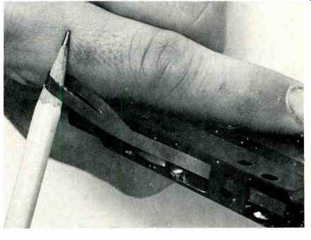
Fig. 1--Tape with a ragged edge is a common indicator of a machine alignment
problem. Severe edge damage can result in a seized or jammed cassette.
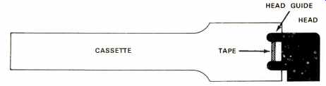
Fig. 2--An accurately aligned head guide will position the tape exactly
in the center of the cassette, as shown here.
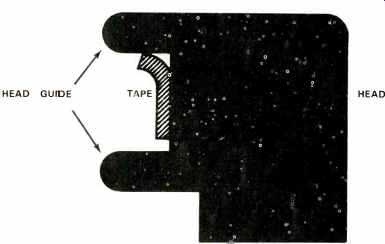
Fig. 3--If the head guide is either too low or too high, it will stretch
or bend the tape edge.
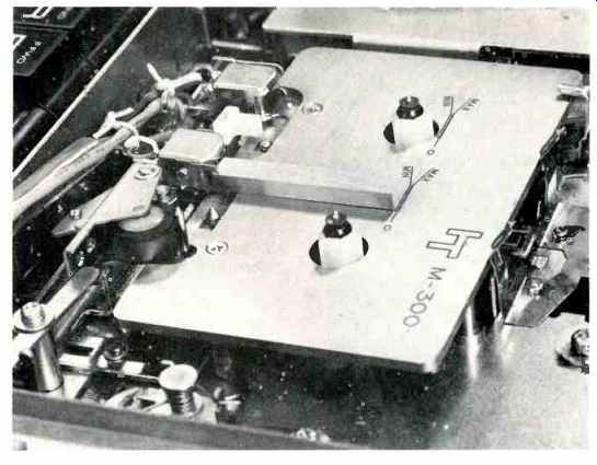
Fig. 4--The metal gauge finger on the mechanical alignment fixture serves
two purposes. It checks head guide alignment by siding between the head
guides when correctly aligned. Secondly, it checks head penetration,
indicating proper penetration on the lines scribed on the surface of the
plate.
Detecting and Diagnosing Alignment Problems
The first and most important step in the diagnosis procedure is to test the machine with a premium quality cassette. A poorly-constructed, bargain basement variety cassette can produce symptoms similar to those of a misaligned cassette machine, making accurate diagnosis difficult, if not impossible. Just as machine alignment and tape path are critical, so is the tape path and guidance system within the cassette. It is the thinness of cassette tape that makes it very susceptible to edge damage, and therefore necessitates a precisely-aligned guidance system.
The major indicator of a machine alignment problem is tape edge damage. This may initially appear as a signal variation in one channel or can be visually observed as an uneven or ruffled edge on the tape. (See Fig. 1.) Edge damage, if severe enough, can result in a seized or jammed cassette, often characterized by tape spilling out of the cassette and being wound around the capstan or pinch roller.
This type of total failure is most common with the 90- and 120-minute cassettes, since they have thinner tape than the 30-, 45-, and 60-minute cassettes.
It seems popular among some cassette machine manufacturers to condemn the longer lengths (C-90, C-120) as unreliable and to discourage their use. This is true if 3-for-$1 variety cassettes are used and/or machine alignment problems exist. There is, however, no reason to avoid using the longer lengths if they are of high quality construction, and if the machine is well aligned.
Another type of misalignment, which may or may not produce the usual edge damage, (i.e., stretch edge), is capstan-pinch roller misalignment. A severe misalignment of these two vital components will usually drive the tape off one side of the pinch roller, often creasing or folding the tape in the process. This usually interrupts the recording to a very noticeable degree.
Head Guide Alignment
An accurately aligned head guide will position the tape exactly in the center of the cassette, as illustrated in Fig. 2. If the guide is too low or too high, it will stretch or bend the tape edge (See Fig. 3). The easiest way to check the alignment of the head guides is with a mechanical alignment fixture.
Information Terminal Corp., 323 The Soqual Way, Sunnyvale, Calif. 94080, sells such a fixture (M-300) for approximately $85.00. The fixture is simply a metal plate that is positioned in the machine where a cassette is normally placed. The top of the plate should line up with the lower guide.
There is a metal gauge finger which serves two purposes. First, it checks head guide alignment. If the head guide is not correctly aligned, the gauge will not slide between the head guides (See Fig. 4). Second, it is a check on head penetration. There are lines scribed on the surface of the reference plate which, when used in conjunction with the gauge finger, will detect excessive or insufficient head penetration.
If the head guides are incorrectly positioned, they must be repositioned by adjusting the head either up or down. However, the azimuth of the head must be maintained; azimuth being the perpendicularity of the head gap to the tape edge. An alignment tape must be used to check the azimuth. This is a reiterative process, requiring that one go back and forth between the mechanical alignment gauge and the alignment tape.
The process of aligning the head should only be attempted by those with proper equipment and experience since it is a delicate process.
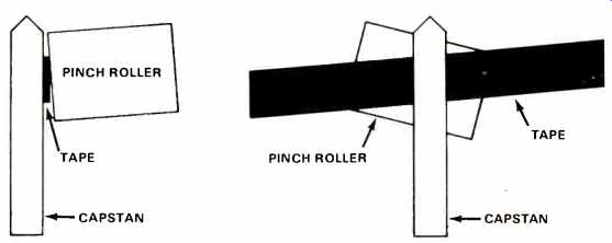
Fig. 5-Both the capstan and pinch roller should be perfectly perpendicular
to the plane of the machine. Deviations will result in the tape being driven
up or down, as shown here.
Fig. 6-A crease along the center of the tape is an indication of tape damage
resulting from misalignment of capstan and pinch roller.
Capstan-Pinch Roller Alignment
The ideal machine has the axis of the capstan and pinch roller perpendicular to the plane of the cassette. Deviations from true perpendicularity will result in the tape being driven either up or down by the action of the capstan pinch roller (See Fig. 5). Typical tape damage resulting from such mis-alignment is illustrated in Fig. 6.
This type of misalignment is very difficult to diagnose, since it is often erratic and inconsistent. It depends upon many variables, such as tape thickness, pack size, and take-up tension of the machine. The best way to diagnose this problem is to watch the tape pass between the capstan and pinch roller. The tape should track in an even line and should not oscillate up and down or track with part of the tape above or below the pinch roller.
Improper tracking is often most pronounced just after starting to play a cassette in the middle. With some machine designs it will be difficult or impossible to observe the tape passing between the capstan and pinch roller.
The only alternative is to repeatedly start and stop a cassette in the center of the pack, then, using a pencil placed through the hub, slowly rewind the tape while watching for damaged sections, such as that shown in Fig. 6.
If your machine has evidence of capstan/pinch roller misalignment, correcting the problem can be a major job. The easiest problem to correct is a worn pinch roller or bent pinch roller assembly. The roller and supporting bracket are often serviced as an assembly, and replacement of this assembly may correct the alignment problem. If it does not, the misalignment may be caused by a worn capstan bearing, a bent capstan shaft, or misalignment of the assembly as it came from the manufacturer. Correction of this more serious problem may require shimming the support plates for the capstan or pinch roller, bearing replacement, etc.-all of which should be left to those with experience and skill in this area.
Selecting a Competent Service Technician
Most tape machine repair facilities do not possess an alignment gauge nor the knowledge to use one. Certainly before submitting your machine to a repair service for realignment, you should determine the competency of the person who will be doing the work.
If the service man cannot satisfactorily answer questions on head guide and capstan/pinch roller alignment and the resulting effects on tape damage, don't hand over your machine. You may have it returned in worse condition than before "servicing." It is possible to check the alignment by purchasing an alignment gauge, as previously noted. Although somewhat expensive, the gauge may pay for itself by reducing tape damage or by saving an irreplaceable recording.
(Audio magazine, Sept. 1974; Neal Rayborn)
Also see:
Logic Control of Tape Recorders (Apr. 1973)
A New Idea for Measuring Wow and Flutter (Jun. 1973)
= = = =