MANUFACTURER'S SPECIFICATIONS:
Frequency Range (Coverage): 50 kHz to 29.7 MHz.
Sensitivity for 10 dB (S+N)/N: AM, 1.0 pV from 400 kHz to 20 MHz, 1.5 pV from 20 MHz to 29.7 MHz; SSB, 0.5 pV from 400 kHz to 20 MHz, 0.75 pV from 20 MHz to 29.7 MHz; CW, 0.25 pV from 400 kHz to 20 MHz, 0.35 pV from 20 MHz to 29.7 MHz.
Frequency Stability: ±40 Hz, after 30 minute warm-up.
Image Rejection: 70 dB.
R.F. Blocking: 100 dB to 1 pV.
Cross Modulation: 65 dB to 1 pV.
Intermodulation: 65 dB to 1 pV.
R.F. Bandwidth: 4 or 8 kHz for -6 dB on AM.
Audio Notch Filter. More than 25 dB at 5 kHz.
Hum and Noise: 55 dB re: full output, 1 mV input, 8-kHz bandwidth, 90 percent 1-kHz modulation.
THD: 0.6 percent for 50-percent modulation, 1.0 percent for 80-percent modulation, 1.5 percent for 90-percent modulation; AM, 1-MHz, 1-kHz modulation, 1-mV r.f. input, 8-kHz bandwidth.
Audio Output: 2 watts at 4 ohms, plus 1.0 V rms into 5-kilohms external output.
Power Requirements: 110-120/220-240 V a.c., 50/60 Hz, switch selectable; 30 watts.
Dimensions: 17.5 in. (44.45 cm) W x 5.1 in. (12.95 cm) H x 15 in. (38.1 cm) D.
Net Weight: 16 lbs. (2.7 kg).
Price: $1500.00.

We suspect that many readers of Audio magazine, in addition to their interest in high-fidelity audio equipment, are also interested in quality reception of programs on the other broadcast bands, that is in AM and short-wave, both continuous wave and single sideband. Few, if any, FM stereo tuners are equipped with anything but the most minimal kind of broadcast-band AM circuitry, let alone facilities for tuning to short-wave frequencies. McKay Dymek's Model DR-33 receiver provides the means, for those who can afford it, to hook in a truly remarkable AM tuner which is one of the very finest all-wave receivers ever made available to general consumers.
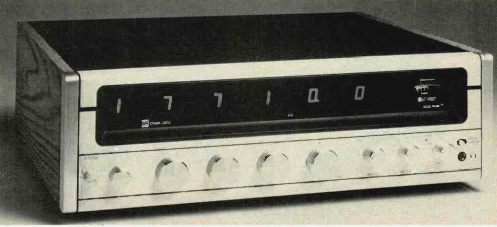
The McKay Dymek DR-33 is a fully synthesized, solid-state, triple-conversion general coverage receiver intended for the reception of AM, single sideband or continuous wave (CW) signals in the frequency range from 50 kHz to 29.7 MHz. It offers extreme accuracy and convenience of tuning, with the tuned-to frequencies displayed in large electronic-readout digits spread across the upper half of the front panel. The receiver is designed for use either as a self-contained unit with its internal speaker or for connection to an external speaker or a hi-fi system or tape recorder.
The second through fifth larger knobs on the lower left section of the panel are used for precise frequency selection.
These knobs select frequencies in 10 MHz, 1 MHz and 100 kHz steps, with the fourth knob of this group selecting frequencies in 5 kHz increments and controlling the last two digits of the LED readout. A fine-tune knob, beyond those mentioned, covers a range of 5 kHz and is a multi-turn control for increased tuning ease and resolution when receiving SSB or CW signals. A "band" control to the right of the knobs just described has five settings: 0.05-29.7 MHz Preamp (the "normal" setting for people in favorable or average listening areas), 0.05-29.7 MHz (when only moderate sensitivity is required), "Local" (with sensitivity reduced some 30 dB), and 2.5-29.7 MHz (in which a filter is introduced to reduce interference from strong local stations, when only short-wave listening is desired).
The mode switch and the i.f. filter switch knob at the extreme left of the panel are usually used together. The former has settings for AM, SSB, CW or RTTY (Radio Teletype signals). The six-position i.f. control determines the upper limit of the audio frequency output of the receiver. It includes 4-kHz and 8-kHz positions for AM listening, "L" and "U" settings for upper and lower sidebands during SSB reception, and "A" and "B" positions which allow for addition of optionally available mechanical filters having bandwidths of 400 Hz (CW), 1200 Hz (RTTY) and 2500 Hz (for narrow AM reception.).
The i.f. gain and volume/on-off controls are concentrically mounted below the "S" meter of the receiver, at the lower right of the panel, while nearby is a noise-limiter switch which, when turned on, helps to eliminate impulse noise and other interference while receiving in the various modes. A stereo-type headphone jack is located below the noise limiter switch and, although reception via this jack will obviously be monophonic, headphones used with the receiver should be equipped with a stereo phone plug (ring, tip, sleeve contacts) for proper operation.
The rear panel of the DR-33 has a recessed line voltage switch, an internal speaker on-off switch, a tuner level control (which adjusts level at the tuner output jack, also located on the rear panel), an i.f. output jack (which makes available the 455-kHz i.f. signal, and a "mute" jack (useful when using the receiver along with a transmitter) which comes equipped with a shorting plug for signal continuity. Antenna connections may be made by means of a transmission line terminated in a phono-tip plug or by means of terminals which accept the stripped ends of antenna and ground lines. Nominal input impedance is 50 ohms.
Circuit Description
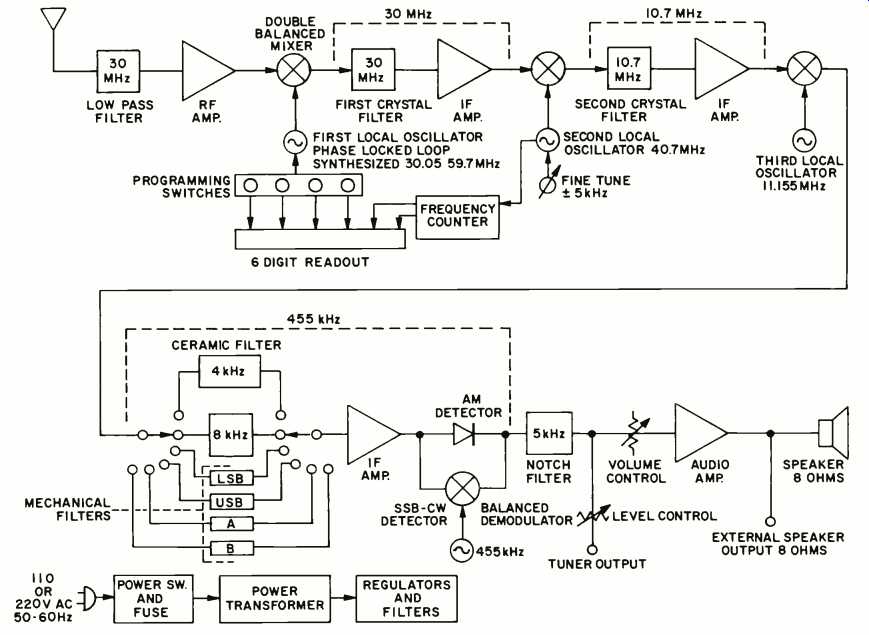
Fig. 1--Block diagram.
Fig. 1 is a block diagram of the DR-33 receiver. Beginning at the antenna, the signal proceeds through a 30-MHz low-pass filter. A broad-band r.f. amplifier comes next, and a switch (not shown) on the "Band" control allows for by-passing this stage, while another position on that switch introduces 30 dB of attenuation ahead of the mixer stage. Also not shown is the high-pass filter setting of the "Band" switch, mentioned earlier, which blocks out all signals below 2.5 MHz.
The double-balanced mixer has two inputs; one contains the incoming signals, while the other is the first local oscillator frequency selected by the four programming switches de scribed earlier. The oscillator operates 30 MHz higher than the tuned-to frequency. The first i.f. section, therefore, operates at a high 30 MHz. A 40.7-MHz crystal-controlled second local oscillator signal, along with the 30-MHz i.f. signal, is then applied to the second mixer to produce a 10.7-MHz signal which is again amplified. The output of the 10.7-MHz amplifier is applied to a third mixer together with the output of a crystal-controlled third local oscillator to produce the final difference i.f. frequency of 455 kHz, which signal is then amplified by yet another stage. This signal is then applied to one of the two detectors, depending upon the setting of the "Mode" control.
In the AM setting, an envelope detector, using a Class-D transistor rectifier and r.f. filter, is used to recover desired audio, while in the SSB mode, signals are recovered by means of a product detector. Since short-wave signals may be as signed frequencies only 5 kHz apart, a notch filter tuned to 5 kHz is included in the DR-33 to eliminate possible beats between adjacent short-wave channels. At the output of this filter, audio signals branch to the tuner output through a rear panel level control and, via the front panel volume control, to an audio amplifier which delivers 2 watts of audio power to the internal speaker or to a connected external speaker. A rear panel switch disables the internal speaker when an external speaker is used or if the tuner output is fed to an associated high-fidelity component system.
Measurements and Listening Tests
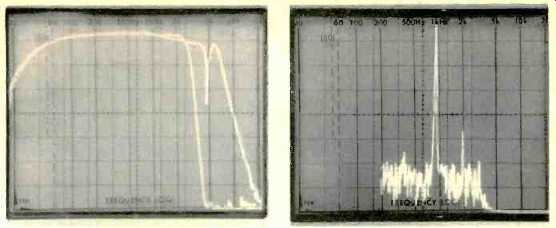
Fig. 2--Frequency response of tuner output. Wider response, with 8-kHz
i.f. setting, shows effect of 5-kHz notch filter.
Fig. 3--One-kHz output (tall spike) shows a relatively small 2nd harmonic distortion component at 2 kHz, which is some 47 dB below reference level.
My lab is not equipped to measure all the capabilities of a receiver such as the McKay Dymek DR-33, still, even with my vintage 1950 AM generator, I was able to verify sensitivities on the broadcast band of--are you ready for this?--0.7 microvolts for 20 dB (S+N)/N,, referenced to 30 percent modulation. As for frequency response, Fig. 2 tells the story.
It is a spectrum analyzer sweep from 20 Hz to 20 kHz and shows response for the 4-kHz and 8-kHz bandwidth positions of the i.f. filter switch. Note that in the case of the better of the two curves, the notch filter pulls out any 5-kHz beats, but then the response jumps right up again, rolling off finally at around 7 kHz.
Figure 3 shows the harmonic distortion components for a 50 percent modulated AM signal fed to the antenna terminals at an intensity of 1 millivolt. The fundamental (center spike) is 1 kHz and scope vertical sensitivity is 10 dB per division, as usual, so that the 2nd harmonic contribution is down some 47 dB from the fundamental. That works out to a distortion percentage of 0.45 percent. Try comparing with that figure with the AM tuner section of any super-fi stereo receiver.
Tuning accuracy is, of course, as precise as can be read on my digital frequency counter--and that's more precise than you can imagine. Anyone who has tried to tune to and hold onto some of those elusive overseas short-wave broadcasts using conventional all-band receivers will immediately appreciate being able to tune to within 0.1 kHz of a desired frequency from 50 kHz to 29.7 MHz.
My only criticism of the McKay Dymek sample I have in my lab is that listening to the hundreds--no, thousands--of transmissions of all kinds that constantly permeate our atmosphere has proven to be so fascinating that I haven't been able to turn my attention to more urgent testing projects that are waiting to be finished. Happily, McKay Dymek was kind enough to send along their Model DA-100 all-wave receiving antenna, a two-part omnidirectional antenna consisting of an external module (mounted outdoors) and an internal module which contains power supply, attenuator, and impedance switch. Combined with the DR-33 receiver, one can obtain short-wave and AM broadcast reception that is truly beyond belief.
While I was unable to measure some of the more subtle performance specifications of the receiver, I have no doubt that they are met or exceeded, judging by the few measurements I was able to make. And now, if you'll excuse me, I have to run--I think I hear Australia coming in over the DR-33 which is still on the test bench in the next room!
-Leonard Feldman
(Source: Audio magazine)
Also see:
McKay Dymek AM-5 AM Tuner and DA-5 AM Antenna (Aug. 1976)
Marantz Model 2500 Stereo FM/AM Receiver (Feb. 1978)
= = = =