MANUFACTURER'S SPECIFICATIONS
Power Output: 200 watts per channel into 8 ohms; 300 watts per channel into 4 ohms.
Distortion: Less than 0.2% at 200 watts; typically 0.01%.
Hum and Noise: Better than 100 dB below rated output.
Input Sensitivity: 2.0 volts.
Damping Factor: Greater than 1000.
Frequency Response: 2 to 65 kHz +0-3 dB
Dimensions: 19 in. W x 11 in. D x 5 1/4 in. H.
Price: $685.00.
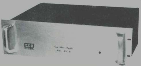
The BGW 500R is a very professional looking piece of equipment with its chrome handles and rack-and-panel construction. Nothing is visible on the front panel except a tiny indicator light-and the BGW logo. The panel itself is very heavy, about 12 gauge I'd say at a guess, and the amplifier itself turns the scales at 42 lbs. No lightweight, this 500R! At the rear are two pairs of heavy-duty output terminals, two input jacks, and a circuit-breaker on-off switch. No fuses are used, which will not surprise our regular readers who will remember designer Brian Wachner's article in our February, 1973, issue. More about this later.
Under the black perforated metal shield, the layout is nice and clean. The output transistors are mounted on two heatsinks, which run almost the whole length of the chassis across the middle. Behind them are two power transformers and the circuit boards are stacked vertically at the rear.
Figure 2 shows the underneath view of one of the heatsinks, which incidentally are 14 inches long with a total radiating area of 560 square inches.
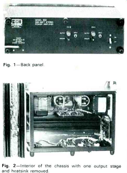
Fig. 1-Back panel. Fig. 2-Interior of the chassis with one output stage and
heatsink removed.
Circuit Description
Input stage is an LM 318 IC, which has a large overall negative feedback loop around it and a NPN-PNP pair, which is then followed by the power driver and output stages. Each output stage uses three NPN silicon devices-a total of 12 for the two channels. The power supply arrangement is a little unusual as two power transformers are used in a series-parallel circuit. In other words, the inputs are in parallel but the secondaries are in series. The Crowbar protection circuit employs a thyristor to discharge the energy in the capacitors and turn off the supply in the event of a short circuit or high overload surges. Two transistors are used to limit the current in the output transistors. The d.c. supply measured 75 plus 75 volts, and this dropped to 63 plus 63 volts under full load. In series with the power transformer primary is a 4 ohm resistor and a relay shorts out this resistor after a one second delay, thus preventing switch-on surges.
Measurements
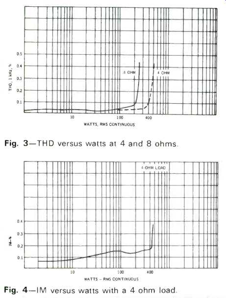
Fig. 3--THD versus watts at 4 and 8 ohms. Fig.
4--IM versus watts with a 4-ohm load.
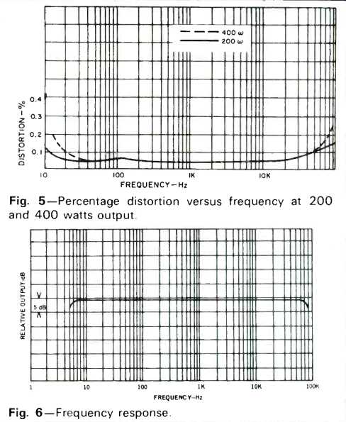
Fig. 5--Percentage distortion versus frequency at 200 and 400 watts output.
Fig. 6--Frequency response.
Figure 3 shows the power output and THD for 8 and 4 ohm loads. Both channels were driven simultaneously, and it will be seen that the 500R delivers more than 225 watts at 8 ohms and over 400 watts per channel at 4 ohms. Nearly a kilowatt! IM distortion (60 Hz and 7 kHz, 4:1) is shown in Fig. 4. Full rated power is stated at 300 watts per channel into 4 ohms; this is a very conservative figure and we obtained nearly 400 watts per channel from 20 Hz to 20 kHz.
Power bandwidth is quoted as being "less than 10 Hz to 20 kHz," but we found the 3 dB point to be above 40 kHz.
Distortion versus frequency for 200 watts and 400 watts is shown in Fig. 5. Frequency response is shown in Fig. 6, the 3 dB points being 5 Hz and 90 kHz respectively. Square wave responses at 40 Hz and 10 kHz can be seen in Fig. 7.
The high frequency waveform shows a slight rounding but there is no trace of overshoot--even with a simulated electrostatic loudspeaker load. Rise time is given as 5 microseconds.
Hum and noise were not too easy to measure due to outside electrical interference, but it lies within 100 to 125 dB as claimed. Input voltage required was almost exactly 2.0 volts for full output.
Listening Tests
How did it sound? In one word, neutral. Which is how it should be. After all, distortion was virtually unmeasurable and it did not increase at low levels. There was no sign of crossover distortion even at milliwatt outputs and overload characteristics were excellent. Bandwidth and rise time were more than adequate; so was stability with complex loads.
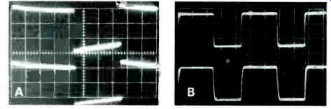
Fig. 7--Square wave response at A, 40 Hz and B, 10 kHz.
Two preamplifiers were used, a Harman-Kardon Citation 11 and a Sony 2000F. Both gave first-class results. Bass was tight, treble smooth with no trace of stridency. Much of the program material consisted of master tapes and disc recordings of impeccable quality. Power was ample for a pair of AR LST's or EPI 400's. Unfortunately, we had to return our Magneplanar speakers just before we received the amplifier, so I missed the opportunity of comparing the 500R with the Audio Research 75+75 with those speakers. Perhaps later....
Summing up: The BGW will unquestionably take its place among the top four or five high quality amplifiers. It is well made with the welded steel construction and all the components appear to be high grade. At $685, it is not cheap, but, after all, this is only 80¢ a watt! My only criticism concerns the lack of VU meters. Yes, I know the answer, but I still like the idea! I almost forgot; there is no switching thump. That relay really works.
-G.W.T.
(Audio magazine, Oct. 1973)
Also see:
BGW Systems Model 500D Basic Power Amplifier (Equip. Profile, Dec. 1975)
BGW Systems Model 203 Stereo Preamplifier-Control Center (Equip. Profile Nov. 1977)
= = = =