Manufacturer's Specifications:
IHF Power (Total): 320 watts, 8-ohm load; 500 watt, 4-ohm load.
RMS Power per Channel: 110 watts, 8-ohm load; 130 watts, 4-ohm load.
THD: Less than 0.1% at rated output; less than 0.05% at 1 watt.
IM Distortion: Less than 0.1% at rated output; less than 0.03% at 1 watt.
Frequency Response: 5 Hz to 200 kHz, +0,-2 dB.
IHF Power Bandwidth: 5 Hz to 35 kHz. S/N Ratio: 110 dB below full power output, short circuited input.
Damping Factor: 170 at 8 ohms, 1 kHz.
Input Sensitivity: 1.4 volts.
Input impedance: 75 k ohms.
Dimensions: 15 3/4 in. w x 5 7/8 in. h x 12 3/4 in. d.
Suggested retail price: $349.50 (optional walnut case extra).
It's been just about two years since we reviewed Sony's preamplifier-control chassis, Model TA-2000 (AUDIO, Dec. '68) . At that time we ( and Sony) would have had to recommend a competitor's power amplifier as the only worthy companion to this magnificent preamplifier.
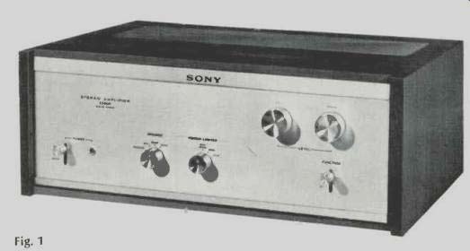
With the introduction of the TA-3200F Stereo Amplifier the people at Sony need no longer be put in that embarrassing position, for this new "powerhouse" is ideally suited for use with that, or any other high-quality professional or semiprofessional control chassis. While strictly speaking, the TA-3200F is a "basic" power amplifier, it does offer some of the flexibility of an integrated amplifier, as can be seen by examining the front panel layout shown in the photo of Fig. 1. At the lower left of this solid gold anodized extruded front panel is a lever-type power on/off switch and an indicator light. A rotary speaker selector switch fellows, with positions for "main," "remote," "both," or no speaker systems.
With no headphone jack supplied on the TA-3200F, one might wonder why there is an "off" position on the speaker switch. Sony chose to omit a headphone jack because the preamplifier mentioned earlier (TA-2000) is equipped with one and when it is used it is desirable to turn off all speaker systems. This makes sense in any case, since most users of basic power amplifiers often mount this component in out-of-the-way inaccessible places, whereas a preamplifier-control chassis, as the name implies, is always accessible and is the right place for a headphone jack in such component installations. Because of the tremendous power handling capacity of the TA-3200F, Sony wisely incorporated a power limiter switch with settings for 100 watts, 50 watts, and 25 watts. This innovation is intended for speaker protection and limits the maximum power per channel to that indicated by the setting of this control. A knowledge of maximum power handling capacity of associated speakers is necessary in order to take advantage of this feature, but more and more speaker manufacturers are now including this data in their literature since higher powered solid-state amplifiers have appeared in recent years.
At the upper right of the control panel are individual level controls for left and right channels. Finally, at the lower right is a lever switch which selects one of two pairs of inputs. We have not seen this feature on any basic power amplifiers previously but the more we think about it, the more sense it makes. For one thing, some users may want to feed certain high-level signal sources directly into the power amplifier, bypassing any preamplifier-control chassis altogether.
(A tuner having its own level controls and even tone controls would be a typical component which lends itself to such connection). At the same time, other high-level sources and low-level sources such as phono, microphone, tape head, etc. must be fed to a preamplifier before they can be applied to a basic power amplifier.
As Sony suggests in their well written customer's manual, the "two input" feature is also useful for comparing two signal sources or two preamplifiers. At the left of the rear panel are the four inputs jacks associated with the two input stereo pairs. The "Normal/Test" switch located directly below the input jacks activates a low-frequency cut filter. In the "test" position, frequency response extends down to 5 Hz, as stated in the specifications. With the switch set to " Normal," frequencies below 30 Hz are attenuated at a rate of 6 dB per octave and this setting is recommended by the manufacturer for the elimination of IM distortion that might be caused by sub-audible rumble frequencies, etc. Two convenience a.c. receptacles (one switched, one un switched) are provided on the rear panel, as well as eight short-proof terminals for the two pairs of speaker systems with which the amplifier can be used. The terminals are widely spaced and are color coded (red for "hot" leads, blue for "common" of "ground" leads). Each terminal has a push button which, when depressed, exposes a hole just large enough to accept a speaker lead.
When released, the speaker lead is locked in place by spring action. No twisting of wire under the head of a terminal screw is required, nor are any tools needed for making a safe and permanent speaker-wire connection.
We thought we had seen some pretty big power transformers (especially when one thinks back to high-powered tube type amplifiers), but the one used in the Sony TA 3200-F probably beats them all, as can be seen in Fig. 3. Occupying fully 1/4 of the cubic volume of the amplifier, it is flanked by a pair of 8000-micro farad filter capacitors, vertically mounted p.c. boards, and a massive quartet of heat sinks--one for each of the four output transistors. The amplifier, by the way, weighs just under 31 pounds out of the shipping carton.
Circuit Description
To avoid the use of large output coupling capacitors, the TA-3200F employs both positive and negative power supplies. This permits direct coupling between output transistors and loudspeaker. This approach improves ultra low frequency response, provides somewhat higher power output and ensures full damping factor and better transient response at very low frequencies. The silicon transistors used in this circuit (both low-level and output stages) have a cut-off frequency sufficiently high to provide essentially flat frequency response up to 30 kHz even before negative feedback is applied. With a full 40 dB of feedback applied in the main feedback loop, response extends from 5 Hz to 200 kHz within 2 dB. Protection circuits for both output power transistors and for the loudspeakers are incorporated in the TA 3200F. Since the latter form of protection is rather unusual in a power amplifier (most better amplifiers have some form of output-stage protection), we will describe it in some detail. Referring to Fig. 3, the output signal is extracted from the output terminal through a low-pass filter (R-140 or R-240, C-313 and C-314) and fed to a bridge rectifier (D-307 through D-310). Because of this filter, the only voltage applied to the bridge rectifier is the very low-frequency or d.c. component that might be caused by transistor faults.
When the d.c. rectifier voltage becomes great enough, it turns on a Hartley oscillator circuit (Q-303 and T0 ). The oscillator output is rectified by D-311 and thus provides trigger voltage for SCR-D-317. When trigger voltage is applied to the gate of the SCR, the SCR turns on and shorts the base voltage of one driver transistor to ground through D312, the SCR, and D-315. The base voltage of the other driver transistor is also shorted to ground through D-313, the SCR and D-314, stopping any current flow in the output stage and thus protecting the speaker system. The bases of driver stages of the opposite channel are similarly affected, as can be seen in the partial schematic of Fig. 3.
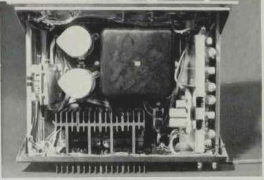
Fig. 2--Top view. Note size of transformer.
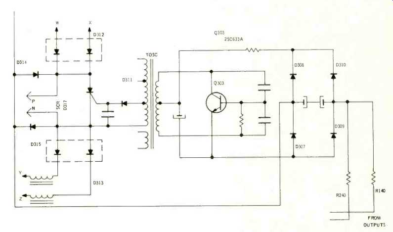
Fig. 3--Partial schematic of protection circuit. W, X, Y and Z go to the
driver transistor basses. and N are connected to a Power Limiter or clamping
circuit.
Performance Measurements
We have noted, of late, that test equipment limitations have prevented our being able to measure down to some of the claimed specifications of the more recent high-grade equipment which this department has reviewed. In view of this, we have just completed major revisions in our laboratory facilities and are now able to measure accurately down to 0.01% THD and down to 0.25% IM. This represents a capability improvement of the order of about three to one over our previous set-up. Despite the up-grading of our laboratory facilities, some of our measurements of the Sony TA-3200F were still limited by test equipment, as can be seen by examining the curves of Fig. 4. At the high-power end of the curve, we began to see meaningful distortion at a power output of 90 watts and reached the 0.1% rated distortion at 110 watts, exactly as claimed. In the case of IM, meaningful readings were obtained at a power output of 80 watts, with the rated figure (0.1%) reached at about 105 watts. Both sets of curves were obtained with both channels driven. Figure 5 depicts the frequency response of the amplifier (both channels were virtually identical, and so only the left channel response is shown ), and also shows the effective action of the "Normal-Test" rear panel switch described earlier. Power bandwidth, shown in Fig. 6, exceeded claims, extending from 4 Hz to 40 kHz.
Bear in mind, however, that we are referring all these measurements to a rated distortion of only 0.1%. Were we to use a reference of 0.5% or even 1.0% (a more typical rating), all of the figures, including power bandwidth, would be even better. Since Sony's published specifications and descriptive literature made a point of the consistency of damping factor at all frequencies, we decided to measure this rarely plotted characteristics. As nearly as we could tell (and it took a great many 1-ohm resistors in parallel to reach the equivalent "internal resistance" of the amplifier), the "looking back" impedance of this remarkable amplifier is approximately 0.05 ohms.
Divided into 8 ohms, this represents a damping factor of 160-close enough to the claimed 170, in view of the difficulty of measurement. As can be seen in Fig. 7, the value held constant at all frequencies from below 20 Hz to above 2 kHz. It should be pointed out, however, that in order to take full advantage of this extremely low internal impedance, heavy cable should be used for speaker connections at all distances beyond just a few feet. As an example, the resistance of 50 feet of even #16 gauge wire is about 0.02 ohms. A speaker placed fifty feet from the amplifier and connected by means of 100 linear feet of #16 gauge copper wire (fifty feet for each lead) would therefore encounter an additional 0.04 ohms of "looking back" resistance because of the hook-up wire alone, thereby reducing the effective damping factor to about 90! (And the resistance of the loudspeaker voice-coil plus crossover will reduce it still further! -Ed.)
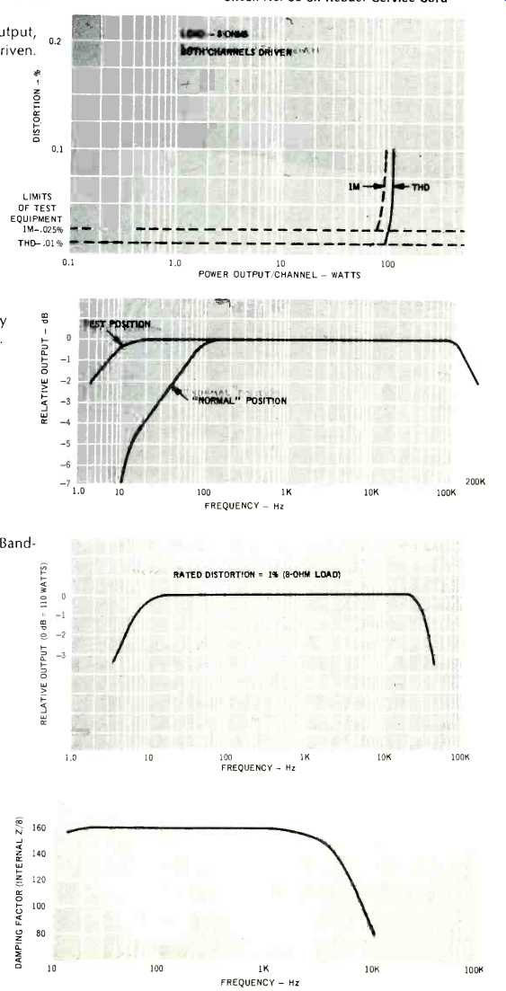
Fig. 4-Power Output both channels driven
Fig. 5-Frequency Response.
Fig. 6-Power Band width.
Fig. 7-Damping Factor.
Listening Tests
To listen to this basic amplifier with anything but equally good associated equipment would be totally unfair to this amplifier and so we borrowed a Sony TA-2000 Preamplifier and a Sony ST 5000F Stereo FM tuner. Retail value of the three units was $1128.50-but what value it was. "Total control" would best describe the combination--and "total purity of sound" would best describe what we heard. For one thing, matching levels were perfect-we operated the TA-3200F with its level controls wide open, and adjusted input levels and volume using only the preamplifier controls.
We used both high- and low-efficiency speaker systems (a pair as "main" and a pair as "remote") and, other than still being able to identify the speaker's inherent characteristic sound, could detect neither distortion nor audible noise or hum from any of the electronics used.
In FM listening, we were somewhat limited by station malpractices, which now became completely obvious. Only two stations in the metropolitan New York area seemed to contribute no noticeable noise or hum to this otherwise noise and hum-free system. In fact, with the preamplifier level and volume controls down and our ear pinned to the high efficiency loudspeaker in a relatively quiet ambience-we could hear nothing, which means that, for all practical purposes, the TA-3200F comes as close to the proverbial "piece of wire with gain" as anything we have seen to date.
-L.F.
(Audio magazine, Nov. 1970)
Also see:
Sony Model STR-7065 Stereo FM/AM Receiver (Equip. Profile, Nov. 1973)
Sony ST-J75 FM Tuner (Equip. Profile, Apr. 1981)
Superscope R-350 AM /FM Stereo Receiver (Feb. 1974)
= = = =