This article should be of use to readers who are interested in the attack that has been made over the past 10 years or so on limitations in the quality of the electronics associated with every high fidelity system. For many years, the quality of the electronic parts of a high fidelity system has been much better in terms of distortion than any of the electromechanical parts such as the pickups and loudspeakers. This is still the case in a well designed system. Nevertheless it is possible, even with distortion in the poorer links of the system, to hear any defects that might exist in the best parts of the system. In the past 10 years, the reasons for these defects have been slowly tracked down. There are currently two main areas of study.
One is the phono preamp, where the newest pickup cartridges and record cutting techniques have placed greater and greater demands upon the low level electronics. The second is in the power amplifier area, where high quality and very low efficiency speakers have placed very high power output demands on the power amplifiers. (This is to say nothing about the bone crushing loudness levels which are now demanded for the full enjoyment of modern popular music.) Interestingly enough, it may be the very same design problems that plague both the preamplifier and the power amplifier. The study of one type of amplifier has yielded insights into the problems with the other. In this article some historical perspective on the efforts that are being made to understand the electronic limitations and the strides that have been made to overcome them will be presented.
Some unifying thoughts about the relationships among electronic problems of signal overload, slew rate limiting, quasi-linear and non-linear distortion, and the application of feedback in amplifying circuits will be considered.
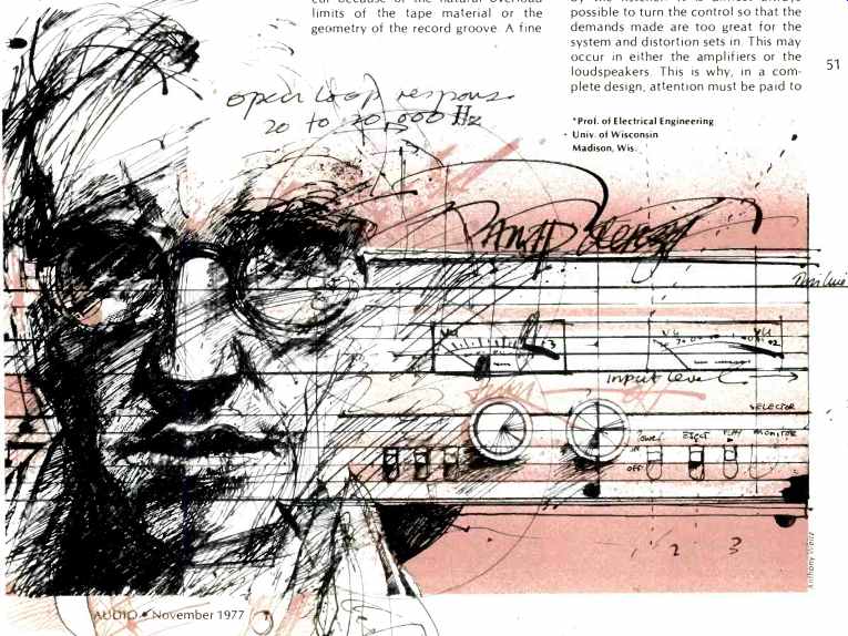
To set the historical perspective for this discussion, I quote four short statements from the literature on power amplifier design. Two of them are from Leach (1). "Basically it (TIM) is an overload phenomenon that is caused by heavy feedback in the amplifier." Later in this discussion reasons for qualifying this comment will be presented which argue that it should read,-We are dealing with an overload phenomenon which is caused by something going wrong in the amplifier that can be greatly exacerbated by heavy feedback. Again quoting from Leach (1), "In summary, the two major design objectives for the prevention of TIM distortion are to design the "open-loop" amplifier for maximum linearity and to design it so that the open-loop bandwidth is at least as wide as the audio frequency spectrum." The third quote is from a 1966 article by Daugherty and Greiner (2). It states, "For high quality audio power amplification, the crucial frequency specification is that the open loop response be at least 20 to 20,000 Hz. Meeting this requirement enables the amplifier to deliver full power at the extremes of the signal spectrum without experiencing transient overloading. Finally, a paraphase from the same article, "It is shown for the high frequency case that if this criterion is not satisfied, transient overloading will occur inside the feedback loop." The excellent article by Leach has brought to the attention of amplifier designers and the audio public both, the work of Otala (3) and some other principles of design that should have been better known for many years.
Why so many designers have ignored the basic rules of design for so long is a little hard to understand. The recent Otala and Leach publications are certainly very important and should be mandatory reading for all persons interested in amplifier design and applications.
Amplifier Design
As the title of this article indicates, I hope to set down some unifying thoughts about the old principles of amplifier design as they relate to the new principles. There are unifying concepts that connect the criteria mentioned above with current thoughts about amplitude and frequency overload and in particular the way these relate to feedback. This discussion will concentrate on power amplifiers, but the concepts are applicable to all types, including preamplifiers, transistor amplifiers, tube amplifiers, FET amplifiers, or any other type of amplifier.
It must be recognized that the signal being dealt with, sound, has a statistical nature. It has a great range of amplitudes and a broad range of frequencies. As it occurs in nature, it will from time to time exhibit peaks in amplitude and/or ranges in frequency that simply cannot be handled by the electronics or any other component in a system, no matter how conservative the design. Thus from time to time some component in the system may overload, either due to a signal that is too large or too fast for the system.
With proper system design this does not happen very often. Unfortunately, when it does happen, the overload can be very troublesome. The ability of the ear/brain to perceive even infrequent overloads seems to be very good, probably better than we would like for full listening pleasure.
This may sound a bit pessimistic.
Fortunately we do not have to deal with signals directly as they occur in nature (except with microphones). When we are trying to reproduce a signal from a recorded source such as a record or tape, the source material has been pre-limited for us. This may not have been done intentionally, such as with a limiter, but it will always occur because of the natural overload limits of the tape material or the geometry of the record groove. A fine treatment of these limits as they occur in records can be found in recent articles by Holman (8, 9, 10). His discussion of the problem is essential to anyone planning to design a preamplifier. The preamplifier must be designed to handle any signal that the pickup might possibly generate without either amplitude or frequency overload. The signal is, of course, greatly amplified by the preamplifier and the power amplifier. The demands upon the electronics both in amplitude and slew rate increase in proportion to the voltage gain necessary to drive the loudspeaker system. These requirements from the pickup to the gain control can be established and remain fixed. From the gain control to the loudspeakers the demand depends on the listener. Every adjustment in loudness that appears to the listener to be about "twice as loud" actually requires almost a 10 dB increase in level.
This means that demands on the amplifiers in both amplitude and slew rate increase about three times for each such increase in loudness demanded by the listener. It is almost always possible to turn the control so that the demands made are too great for the system and distortion sets in. This may occur in either the amplifiers or the loudspeakers. This is why, in a complete design, attention must be paid to establishing the loudness levels desired. A balanced design will then take into account the size of the room, the efficiency of the loudspeakers, and the headroom desired in the electronics. In an ideal design, the only limiting that will take place will be in the program material itself. The amount of headroom necessary is surprisingly large with high quality program material.
Appropriate design criteria will be discussed further below.
Overload Distortion
Gross forms of overload distortion are readily measurable and have been studied for over 15 years. The photographs in Fig. 1 show three examples of amplifiers which have been overloaded with tone bursts. This technique is described in Reference 4 in some detail. In the cases shown, each amplifier has been overloaded by 5 dB above its clipping point for a brief period and then returned abruptly to a normal level of operation. This is a severe form of overload which can upset bias conditions within the amplifier and cause the power supply to sag considerably. The amplifier output shown in the top trace is very good. The other two show serious distortion of the waveform following overload. The bottom amplifier recovers with a thump and crash that is totally unacceptable.
Just as these amplifiers behave quite differently far tone burst overload, they will likely show different forms of single cycle and short transient overload. Improvements in amplifier design, particularly direct coupling and complementary symmetry designs, have produced some amplifiers which are greatly improved in terms of the gross overload problems shown here.
There are unfortunately many power amplifiers and preamplifiers which do not do well on these tests even though the solutions to such design problems are well known.

The main discussions in the present article are directed to the much more subtle types of distortion related to momentary internal amplitude or slew rate overloading. As has been pointed out, occasional overload might take place because of the statistical nature of the musical signal being reproduced.
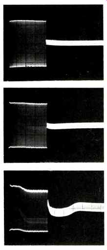
Fig.1--These three photographs show that different amplifiers overload in
quite different ways even though they are presented with the very same overload
conditions. The traces shown are done with the tone burst techniques described
in Reference 4. Note that the top amplifier, with 5 dB overload, recovers
without much difficulty. The other two amplifiers however have considerable
problems and will badly distort the sounds they are supposed to amplify.
Reference 2 describes several criteria that must be met in order that the electronics in a system will perform without substantial audible defect.
One of these criteria is that the headroom of the electronics, i.e. the peak signal handling ability of the amplifier with reference to the average signal level demanded of the amplifier, should be at least 17 dB. This result was derived from data that measured the amplitude distribution of live program sources. This criteria is still valid.
The need for headroom is widely recognized by professionals. Unfortunately some professionals do not allow enough headroom and many high fidelity enthusiasts simply ignore the problem. The greatest fault I have heard with systems I have been asked to audition has been that they are played too loudly for their abilities. A second criterion was set down in the paper which is just as important but which has gone largely ignored until recently. It is that the frequency range of the signals applied to the power amplifier (or any feedback amplifier) should not be in excess of the open loop frequency capability of the amplifier. The reason for this criterion is so that internal overload of the amplifier does not take place either due to amplitude or frequency overload (slew rate overload). Notice that the statement of this rule allows either the selection of an adequate amplifier or the limiting of the bandwidth of the signal. It is usually not the choice to do the latter. This rule implies that each amplifier in the electronic chain must have a bandwidth greater than the previous one in the chain. Many high fidelity systems are a catastrophe because this rule is broken.
The amplitude overload criterion stated above is based on the principle that while an amplifier might be allowed to overload occasionally when driven by a typical statistical (music) signal, that this should happen only a very small percentage of the time. There is a rather detailed analysis to justify the ratio of 17 dB in Reference 2. For the present it is sufficient to note that 17 dB of headroom guarantees that the amplifier will overload less than 0.1 percent of the time even with the best possible program material. In fact the amplifier will overload even less often if the headroom anywhere earlier in the reproduction chain is less than this amount.
This is often the case and thus the amplifier never overloads at all. This principle should be used to select the proper sized amplifier after the loudness level desired, the loudspeaker efficiency, and the room size are all known.
It is not only protecting the amplifier from overload that is important but also selecting an amplifier that recovers well from overload when it occurs. With most amplifiers designed to drive an 8 ohm load the most common form of overload is voltage limiting. This is usually a well-behaved type of limiting that results in chopping off the tops of the peaks in a clean fashion. Many designs do very well in this mode of limiting and recover immediately. In a few cases the amplifier may go into brief oscillation.
Amplifiers that do this should be avoided. At lower impedance levels such as 4 ohms, or in particular with electrostatic loudspeakers where the load may become capacitive, it is more usual for current limiting to take place. Very often current limiting in an amplifier is accomplished with complex current detection circuits within the amplifier. These are difficult to design and can cause complex overload distortions as well as delays in recovery from overload. Some amplifiers are much better than others.
Possible waveform distortion is shown in Fig. 3. A particularly annoying defect in overload limiting (current protection) is known as chattering.
This can not only be heard but it can burn out tweeters because of the burst of high frequency energy delivered to the loudspeaker. Low impedance loads and current limiting should be avoided if at all possible. Individual amplifiers should be checked for good recovery from both voltage and current overload. Complex equipment is needed to do the job but the amplifier manufacturer seldom delivers the necessary bad news about his equipment. Test reports should certainly do this for the consumer and some do.
Frequency Limitation
The frequency limitation criterion is based on a problem which any feedback system experiences. That is, whenever the output signal differs appreciably from the input signal, the difference signal can get quite large. This actually occurs when there is an amplitude or frequency overload anywhere in the feedback loop. This in turn happens when the input signal is either too big or too fast for the loop response.
The further into the amplifier that the overload occurs, the worse the overload situation becomes. If the limiting comes in the very first stage most of the amplifier is not overdriven. Ideally, frequency and amplitude limiting elements will) be placed just ahead of the first stage. Large amounts of feedback can make the overdrive caused by limiting more severe. It should be emphasized that feedback does not cause the problem, it only exacerbates it. Recognition of this problem has eluded many designers because, even though the closed-loop response might be quite large, the open-loop response is often quite marginal to cover the audio frequency range in high power amplifying devices. The term used for this type of distortion in 1966 was transient overloading or transient inter modulation distortion. The term TIM was not common because it described a special measurement scheme rather than a mechanism of distortion. It might be most appropriate to call this form of overload distortion simply "frequency overload." It must be recognized that frequency overload can be caused by two distinct internal overload mechanisms. One of these is internal amplitude overload and the other is a slew rate limiting. Also, either one of these mechanisms can be triggered by a single signal. No inter modulation test method is needed.
How these various distortions relate and possible solutions are described further below.
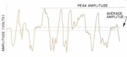
Fig. 2--A complex audio signal might look like the one drawn here. Note that
the peak-to-average values might be as large as seven-to-one for the voltage
waveform. This corresponds to almost a 50 to 1 for the power ratio, or about
17 dB.
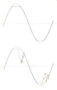
Fig. 3--Amplitude
overload can look relatively good as in the top figure, or it can look quite
bad as in the bottom figure. These representations are for two different
amplifiers under similar overload conditions. The bottom example is close
to chattering, which is a condition that should be avoided if at all possible.
The overload condition should show clean and slightly rounded waveforms,
and quick recovery.
The recent excellent work of Otala (3) and Leach (1) has shown that overload caused by fast changing waveforms in high gain feedback amplifiers is more common now than in years past. This is partly due to the development of very high gain operational amplifiers. Because of the need for heavy frequency compensation and the limited current output capacity of these microcircuits, they exhibited severe slew rate limiting. While any amplifier has a slew rate limit, it was difficult to get enough gain and feedback to get into serious trouble 10 years ago.
During the period when the amplifier is slewing as fast as it can, it is in effect overloaded and thus can not pass small signals. The limiting can take place for high amplitude, high frequency signals, as well as for transient signals which are like step functions. It also occurs for a single signal and in an amplifier that might have only one stage and no feedback at all. Thus the term transient intermodulation distortion is not a very good one. It is also not correct to say that transient distortion is caused by feedback but rather that when it is about to occur that feedback can make it much worse. A very good way to measure for the existence of transient overload in an amplifier is given by Otala and Leach (Fig. 4). This method does not give a very quantitative measure of the distortion. The methods shown by Jung (7) use steady state signals and more traditional measurement techniques. They seem to give more quantitative results for operational amplifiers and seem to indicate fairly well which amplifiers are best. However, they are quasi-linear measurements and there is some danger in extending the conclusions to what are certainly non-linear overload effects such as described here. Typical distortion-vs-frequency curves are shown in Fig. 5. Some of the curves seem to rise abruptly and some much more slowly. This would seem to correlate with a soft limiting and hard limiting of the overload mechanism. It is too early to tell which mechanism is the most desirable. I would speculate that the softer limiting causes some distortion all the time, while the hard mechanism distorts very little up to the limit. Thus when the hard limiting mechanism persists, it is even more important to design the system with adequate headroom. Whichever method is used to measure the distortion, it is clear that progress is being made in both understanding the design problem better and in actually creating better amplifiers.
Design Differences
Different designs behave quite differently when they are frequency overloaded, just as is the case for amplitude overloading. Some amplifiers recover quickly and some have a hard time of it. Each individual design must be checked for these overload problems. A good testing laboratory could provide the needed data to the consumer. There are two questions to consider. One is how to design an amplifier that overloads gracefully and recovers quickly. The consumer has little control over this. The second is how to select an amplifier for a given application that will overload as seldom as possible.
Fortunately the consumer is not helpless in making meaningful decisions regarding the latter consideration. In the case of power overload, we need to know the peak voltage or current overload point of the amplifier.
For frequency overload we need to know the maximum slew rate of the amplifier. If we never exceed the voltage or current limits of the amplifier there will be essentially no amplitude distortion. If we never exceed the slew rate of the amplifier there will be no transient overloading.
Regardless of what you call it, TIM, SID, SRL, TOD, or whatever, we must design the system to prevent or minimize overloading and in particular, overloading of circuits that do not overload "gracefully."
In order to establish some perspective on rules for system design involving any amplifiers and power amplifiers in particular, I will review in summary form some of the statements made in Reference 2. "The design of an audio amplifier capable of high-quality performance requires first that proper design objectives and principles be established. To determine these objectives and principles it is necessary to treat the amplifier as part of a complete transmission system intended for a specific purpose. This implies considering the nature of the source, the program to be transmitted, the load, and also comparing the amplifier transmission characteristics with those of the other links in the system. By this means, the working conditions and operating requirements of the amplifier can be derived and design objectives and principles can be developed. Three important areas for which treatment is required are: 1) steady state and transient frequency response, 2) power levels and overload response, and 3) nonlinear distortion." Four additional short quotes are appropriate here. "The open-loop response must be at least equal to the overall response of the portion of the transmission system preceding the power amplifier.... (if this) condition is not satisfied, transient overloading will occur inside the feedback loop.
This transient overloading will cause appreciable distortion if the amplifier recovers slowly due to capacitor charging or transistor saturation." and " ... it is likewise impossible to say that W watts of amplifier power will always be adequate. The best one can do is to say that the orchestra will probably produce less than X watts/ meter' P percent of the time. If P is sufficiently close to 100 percent of the time, clipping will be infrequent and clipping distortion will therefore be 'negligible. Thus it is evident that the amplifier power requirement must be based on statistical considerations." and " ... we find that for 0.333 percent of the time the signal exceeds a level of 17 or 18 dB above the rms. Thus a clipping margin of at least 17 dB is required (for this case)." and finally, "As noted in the discussion on frequency response, slow recovery from amplifier overload can cause overload distortion to become intolerably large. Thus, for the above overload margin to be applicable, it is required that the amplifier recover very quickly when driven to the point of clipping."
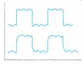
Fig. 4--The test signal devised by Otala shows dramatically when there is
any internal overload of the amplifier.
Internal amplitude or slew rate limiting could be the cause. Comparisons among amplifiers can be made, but it is very hard to make quantitative measurements with this technique.
Basic Rules
In somewhat more modern terminology the following set of basic rules should be followed when choosing an amplifier:
1--The instantaneous peak voltage or current capability of the amplifier with the given load connected must not be exceeded by the demands of the program material. (Within the limits set by the desired probability of overload as determined from the statistics of the signal.)
2--The maximum rate of change of the voltage that the power amplifier can deliver to the given load must not be exceeded by the demands of the program material at any combination of frequency and peak output voltage required. (This rule is related to frequency overload.)
3--Rule No. 2 can be restated in terms of frequency response or slew rate as follows: a) the closed-loop slew rate of the amplifier must be greater than the demands of the program material, or b)
The open-loop bandwidth of the amplifier must be greater than that of the program material. (Both statements under the same level and load restrictions as in Rules No.1 and 2.)
4--If both types of overload are minimized, as they will be in a well-designed system, then the distortion levels can be made as low as needed by application of sufficient feedback. The actual amount of feedback is not a major factor as long as a good stability margin is maintained and overload minimized.
5--If it is expected that either amplitude or frequency overload will occur, then one or more of the following solutions should be pursued.
a) Select an amplifier which will better meet the required criteria.
b) Select an amplifier that will overload in a "well behaved" manner and which will recover quickly from any overload.
c) Limit the program material in frequency range and amplitude so the above criteria are satisfied.
6--All of the elements needed to evaluate the above criteria can be measured in an absolute or statistical manner for both the program material and the amplifier so that a design solution is possible.
7--Discussion of the details of the amplifier design for application in a system are not of much consequence unless at the same time all of the above criteria are addressed.
The application of Rule 1, on voltage and current overload, is covered in several places including Reference 4 Simply stated, the rule requires, for highest quality reproduction, that the amplifier never be called upon to deliver an average power level higher than 17 dB below its peak capability or 14 dB below its average capability as measured by standard sinusoidal steady state techniques. This is a very severe requirement. If the amplifier in question has average reading meters, and they are calibrated to read full output at +3 VU, then they should never read higher than-11 VU average to satisfy this requirement. If the amplifier has peak overload lights, they should essentially never go on.
One must conclude after seeing many home, rock, and reinforcement systems that this requirement for good design is often broken. It is no wonder that amplifiers sound different when they are often overloading. Even in a home system a surprisingly large amplifier is required, particularly with inefficient loudspeakers. Caution in trusting typical amplifier meters and overload lights should be taken. In many cases, particularly with low impedance and highly reactive loads, the amplifier metering circuits will not give a true picture of the overload condition of the amplifier. Often an external oscilloscope measurement scheme is necessary. The meters are usually most reliable with 8 ohm voice coil type systems.
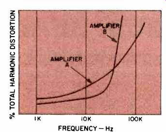
Fig. 5--The shape of the curve showing the onset of distortion may give
some indication of the susceptibility of the amplifier to transient types
of distortion. There is some danger in extending conclusions drawn from steady
state measurements to the prediction of non-linear transient phenomena. Jung's
writings on this topic are quite convincing as they relate to operational
amplifiers, but it is yet to be seen if amplifier A or B is the better in
the case of power amplifiers.
The application of Rule 2 or 3 (whichever form you prefer) is somewhat more complex. Frequency overload distortion, which is caused by slew rate limiting, depends not only upon the frequencies involved but upon their amplitude as well. Slew rate depends directly on the product of the amplitude and frequency. In order to apply the overload criterion we have to make some estimate of the peak amplitude that we expect at the highest frequency demanded and then find the worst case of the product of these two values. At the same time we must recognize that the slew rate size distribution for a random signal will be similar to the peak amplitude distribution for the same signal at a given frequency. Thus we should really evaluate the slew rate overload problem statistically just as was done for the amplitude overload case. We can then be assured that in a given design that the slew rate will not be exceeded for a certain small percent of the time. If we apply the same statistics to the slew rate size distribution as to the amplitude distribution we will again find that about 17 dB of stewing headroom is required between the peak slew rate and the average slew rate of the signal. The highest slew rate for the power amplifier will be for a signal of maximum undistorted power at the high band edge of the amplifier. For example, if we require an amplifier of 100 watts rating into a load of 8 ohms and at a frequency of 20,000 Hz, we have a peak voltage of about 40 volts and a slew rate of 5 volts per microsecond. If the system has been designed correctly, the maximum average power required from the amplifier will be 14 dB below the specified average power capability (17 dB below the peak) which will then be 4 watts average.
Since the same statistics apply to the slew rate, we find that as long as the power headroom is large enough, the slew rate headroom will be large enough as well. Note that we have assumed here that the amplifier will deliver full power without distortion at the highest frequency required. This is not always the case for amplifiers. The work of Jung (7) shows that distortion can set in well below the highest frequency that the amplifier might be expected to pass. More investigation of this problem is required. It is essential that amplifier test reports give slew rate information. In fact it should be given for various loads.
The very same principles apply to preamplifiers, microphone amplifiers, control amplifiers, and the like. All amplifiers can be selected on the basis of their voltage and current overload capability and their slew rate capability. Final judgment about the quality of an amplifier will often depend upon the way it recovers from overload in those rare conditions that it does in fact overload. Unfortunately, with high quality program material and low impedance loads there are conditions where the amplifier can overload more often than might be indicated by casual metering of the power levels.
The most sensitive monitoring technique is with an X-Y oscilloscope applied to the input-output amplifier signals. This technique should be used more often than it seems to be in the equipment test reports.
I believe we are again reaching a point where the electronics in a well designed system will again be considered essentially perfect compared to the other elements in the chain of reproduction. Some additional improvements will come when every designer of amplifiers and systems applies the well known rules.
REFERENCES
1. W.M. Leach, "Transient IM Distortion in Power Amplifiers," Audio Feb. 1975.
2. D. G. Daugherty and R. A. Greiner, "Some Design Objectives for Audio Power Amplifiers," IEEE Trans, on Audio and Electroacoustics, Vol. AU-14 No. 1, March 1966.
3. M. Otala, "Transient Intermodulation Distortion in Commercial Audio Amplifiers," journal of the Audio Engineering Society, Vol 22, No. 4, May 1974.
4. R. A. Greiner, "Power Amplifier Overload Characteristics and Their Importance," Audio, June 1966.
5. W. M. Leach, "Build a Low TIM Amplifier," AUDIO Feb. 1976.
6. W. M. Leach, "Low TIM Amplifier Part II," AUDIO, Feb.1977.
7. W. Jung, The Audio Amateur, 1977 and 2/1977.
8. T. Holman, "New Factors in Phonograph Preamplifier Design," journal of the Audio Engineering Society, May 1976.
9. T. Holman, "New Tests for Preamplifiers," Audio, Feb. 1977.
10. T. Holman, " Dynamic Range Requirements for Phonograph Pre-amplifiers," Audio, July 1977.
(adapted from Audio magazine, Nov. 1977 )
Also see:
Build a Low TIM Amplifier (Feb. 1976)
= = = =