Manufacturer's Specifications
Power Output: 201 watts per channel into 8 ohms from 20 Hz to 20 kHz with no more than 0.05 percent THD.
Power At Clipping: 250 watts per channel into 8 ohms at 1 kHz, 500 watts for 1 channel into 8 ohms at 1 kHz.
Noise: Greater than 100 dB down, IHF A weighted.
Harmonically related "commutation noise" is equal to or less than nonlinear distortion components, IHF A weighted.
SMPTE IM Distortion: 0.05 percent.
Transient Intermodulation Distortion: Unmeasurable.
Frequency Bandwidth: +0, -3 dB, 1 Hz to 250 kHz at 1 watt.
Slewing Rate: 40 volts per microsecond.
Input Filter. +0,-3 dB below 5 Hz.
Output Filter: +0,-3 dB, 0 Hz to 40 kHz.
Display Tracking: ±1 LED digit.
Display Ballistics: Peak responding, 1 millisecond attack, 0.5 second decay.
Dimensions: 7 in. (17.78 cm) W x 7 in. (17.78 cm) D x 7 in. (17.78 cm) H.
Net Weight: 9.5 lbs. (4.32 kg).
Price: $349.00.

It's been a long wait! About two years ago I first heard rumblings about Bob Carver's new amplifier design which he called (and continues to call) a Magnetic Field Amplifier. About six months later, I heard a prototype of this amp at a trade show and, like everyone else who heard it with me, had a temptation to peek behind Carver's display to see if there wasn't a large conventional amplifier hidden away some where that was actually delivering the big sound we were hearing. There wasn't (at least none that we could find with out being too obvious about it).
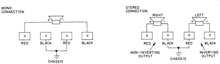
Fig. 1--Unusual speaker terminal arrangement of Carver M-400 amp.
Some six months after that, Bob Carver showed up at my lab with a preproduction model of the Magnetic Field Amplifier, just to give me an opportunity to do some preliminary measurements on the test bench and to do some fast listening. We ran into no problems in the listening tests. In fact, the amp sounded about as open and clean as any power amp I'd measured in recent months. But when we got it up on the bench, I discovered that with my load resistors (which at that time were slightly reactive), we couldn't quite make the 0.05 percent harmonic distortion claim at 200 watts per channel. I think we topped out at about 195 watts. Carver and I would have been perfectly content with that, but when I told him that the FTC might take a dim view of his rating the amp at 200 watts per channel, Carver, the perfectionist, packed up his amp and went back to the state of Washington to do a little more tweaking.
I suspect that his new power rating of 201 watts per channel is his way of telling me (and the FTC) that he not only licked the problem, but managed to squeak out an extra watt or two. I admire a dedicated designer with a sense of humor! And, happily, I admire the result of Bob's two-year effort. It is, to put it mildly, quite an achievement and one that is likely to change the way many of us think of power amp designs in the future.
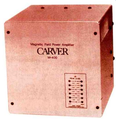
The M-400 amplifier comes in a gold-anodized metal housing that's cube shaped. Nothing remarkable about that until you measure a side of the cube and find that it's only some thing around seven inches in each dimension. You can't appreciate that from the photo, but take my word for it, you will do a double take when you see this 200-watt (excuse me, 201 watt) per channel amplifier in person! Pick it up and you are in for an even bigger surprise. It weighs less than 10 pounds! There are no controls on the front panel, not even a power on/off switch. At the lower right of the panel, however, are two vertical banks of LEDs, each calibrated in dB for a single channel. Specific dB steps are at 0 dB (at the top),-5 dB,-10 dB,-20 dB,-40 dB and "infinity." The last named set of LEDs illuminates when power is applied, even if no signal is being amplified, and also serves another important function. The pair will blink or "strobe" approximately twice per second with diminished brightness to indicate a possible short circuit in a speaker connection or severe overloading. The blinking will continue for periods of from a few seconds to several minutes, depending upon the fault. When proper operation is restored, the display reverts back to its power indication status.
The rear panel of the M-400 contains a recessed pair of phono-tip jacks for inputs, four color-coded speaker terminals, an impedance switch, and a fuseholder with a 15-ampere fuse. The impedance switch is a two-position slide type which is normally placed in its downward position for 4-, 8-, or 16-ohm loads. For mono operation, or for impedances below 4 ohms, the switch is moved to its alternate position.
We were warned in advance to be careful of the color coding of the speaker terminals. The black terminal of the right channel pair is chassis ground, while for the left channel, the chassis terminal is red. In other words, the two channels of amplification deliver out-of-phase signals. To put it another way, you would connect the positive terminal of the right speaker to the red-right output terminal, while the positive terminal of the left speaker would also be connected to the red-left terminal, even though that terminal is chassis ground. For mono operation, you simply connect the single speaker to the two outermost terminals, as illustrated in the diagrams of Fig. 1.
For the home user, none of this unusual arrangement poses any problem whatsoever, since speakers would be connected in accordance with the usual color coding and every thing comes out in phase. For testers such as myself, however, care must be taken not to reference the black-left speaker output terminal to ground. The only unusual result of this bench hookup is that we obtain out-of-phase outputs during bench measurement of the two channels simply because of our need to establish a ground reference.
How It Works
Normally, at this point in any test report, I try to explain, in brief, any special circuitry or theory of operation that relates to the product under test. In the case of the Carver Magnetic Field Amplifier, everything is so new and unusual that such an explanation cannot be brief. Accordingly, in this report, I will simply disclose the results of my bench and listening tests which were conducted in much the same way as would for any conventional amplifier. Readers who want to know how the amplifier works can read my accompanying description, most of which is derived from conversations with, and written material supplied by, the inventor himself.
Laboratory Measurements
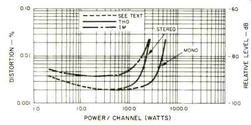
Fig. 2--Power output into 8-ohm loads vs. distortion.
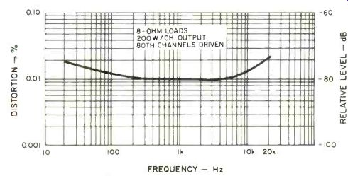
Fig. 3--Total harmonic distortion vs. frequency.
To begin with, we were advised to measure the amplifier with its power cord not connected to our usual Variac, but directly to an outlet. The reason for this will become apparent if you read the accompanying article and, in simple terms, is because the phase angle between current (I) and voltage (E) can be rather extreme as power is delivered from the utility company to the amplifier. Thus, current may be very high while actual power consumed is much lower. This might tend to pop fuses which are rated at only 10 amperes in my bench Variac. All of this preface is simply to explain that at the time of measurement, my own local utility company was delivering only 117 volts instead of the required 120, so some of our measurements may be a bit on the low side, insofar as clipping levels are concerned.
At mid-frequencies we measured 231 watts per channel, both channels driven into 8 ohm loads, before reaching the rated THD of 0.05 percent. SMPTE IM turned out to be just about the same, as shown in the graphs of Fig. 2. The high-end power output is still the limiting factor for this amplifier, but now we were able to read 210 watts per channel output at 20 kHz for rated THD. We must point out that anyone attempting to duplicate our measurement had better make the test quickly. Carver's amp begins to behave more like a conventional amp at high frequencies and therefore cannot deliver continuous rated power at 20,000 Hz for any sustained period. Clearly, this will never constitute a problem during actual use as a music-reproducing amplifier. Distribution of musical frequencies is such that when mid-frequencies are driving an amplifier to full power output, high frequency content is much lower (often 20 dB lower, on aver age, for an ordinary selection).
Even on the test bench, subjecting the amp to 20-kHz inputs for more than a few seconds will not do any harm. It simply shuts down the amplifier. Remove the signal and, after a few seconds, things pop right back to normal with the amp none the worse for the experience.
Harmonic distortion versus frequency for rated power output into 8-ohm loads is plotted in Fig. 3. Referring back to Fig. 2, we should point out that it was somewhat difficult to quantify distortion at low power levels simply because the Magnetic Field Amplifier's unique method of operation generates minute output components which Carver calls "com mutation noise." Some of these components are harmonically related to the test signal, but in general are well outside the audio band. Thus, while our distortion analyzer may read distortion levels of 0.03 percent, if we interject a low-pass filter between the output of the amplifier and the input of our Sound Technology 1700 Analyzer we find that the distortion level drops to the residual value of the generator (about 0.002 percent) even if the cut-off frequency of the filter is set to around 20 kHz.
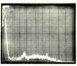
Fig. 4--Wide, linear spectrum analyzer sweep from 0Hzto110 kHz discloses that "commutation
noise" occurs above the audio frequency range. (Scale is 10 kHz per horizontal
division.)
To further verify this point, we reduced the output way down to 1 watt--to reduce the dynamic difference between the signal peak and these residual "noise" components--and swept our spectrum analyzer over its widest range, linearly, from 0 Hz to 110 kHz. In the photo of Fig. 4, disregard the logarithmic frequency notation, and read frequency linearly as 10 kHz per horizontal division. On that basis, the commutation noise peaks at around 28 kHz, well outside the audio band. Even at that, the peak measures about 75 dB below the 1-watt level (reference spike at the left of the display). That works out to a percentage of only 0.0178 percent, whether you call it a distortion component or commutation noise.
Applying an A weighting filter, we measured a signal-to noise ratio (re: 1 watt output) of 81 dB or 104 dB below rated (201 watt) output. Overall frequency response was down 3 dB at 45 kHz, rolled off deliberately by Carver's built-in output filter. The amplifier had a very high damping factor. We measured it using a 50-Hz test signal and results were a DF of 170. Dynamic headroom was a higher than average 1.6 dB.
That means that under short-term musical peaks, the amp could deliver around 290 watts per channel without evidence of clipping! IHF IM and CCIF IM were both too low to be reliably measured. Slewing factor measured slightly higher than the 40 volts per microsecond claimed by Carver. Allowing for the wide spread between LEDs in the display, we found these indicators to be reasonably accurate. As evidently happened to Bob Carver, we weren't able to read significant amounts of TIM when we tried to measure that parameter either.
One of Carver's claims concerning his amplifier has to do with efficiency. Indeed, for an amplifier to pump out that kind of power without heating up to well beyond the melting point of solder, it would have to be pumping most of its power into the load and not into the chassis (what there is of it) in the form of wasted heat. Here are some power consumption numbers to compare with those of any amplifier you may be familiar with: Under quiescent conditions (no signal applied), the amp's total power consumption is a mere 26 watts! When delivering 100 watts per channel to 8-ohm loads, total power consumption is only 550 watts. At full power output (200 watts per channel), total power consumed by the amp was only a bit under 800 watts. During actual use, when reproducing music signals, average power consumption would, of course, be much closer to the 26-watt figure, since average power output will be only a couple of watts per channel.
Listening Tests
We hooked up the amplifier to our latest pair of reference speakers (KEF Model 105-II), which are of medium to high efficiency. We must admit that, having "seen" that commutation noise outside the audio band, we suspected that it might contribute some audible effect during our listening tests. It did not. Music reproduction was superb and completely free of any false bass coloration or muddiness. The amplifier handled the toughest transients we were able to feed to it with ease. To insure against introducing any sonic aberrations from our reference preamp, we switched back and forth using a tuner program source (created via closed circuit in our lab) first fed to the amp via a preamp and then fed directly to the amp.
At no time did the amplifier shut down during our listening tests, despite the fact that we did occasionally push it to clipping or overload for brief periods. Needless to say, at such listening levels we couldn't stay in the room with our speakers for very long and we seriously doubt whether any one would want to listen to such levels on an ongoing basis. Reproduction remained accurate right up to the point of clipping, and there was none of that brittle quality that one often detects from amplifiers that are beginning to strain.
Carver prints a warning on his little amplifier to the effect that it is designed and warranted for consumer hi-fi use only and is not intended for industrial or pro-audio applications. I'm not sure why he did that, but I will predict with a reason able amount of certainty that the incredible portability and small size of this amp is going to tempt many a professional to disregard that warning and use it "on the road" and in live performances. I suspect, too, that it will hold up under such "illegal usage." Even if it does shut down when subjected to unreasonable overload, my own tests suggest that it has so many levels of protection circuitry (none of which, by the way, affected sound quality as far as I could tell) that recovery will be swift and no permanent damage will result.
I must admit that for the better part of last year I was beginning to wonder whether Carver would ever get beyond the prototype stage on this revolutionary new amplifier. Now, having tested and listened to this mighty midget of an amp, I feel that the wait was more than worthwhile.
-Leonard Feldman
================
OPERATION OF THE MAGNETIC FIELD AMPLIFIER
According to Bob Carver, President and founder of Carver Corp., there are two concepts associated with the Magnetic Field Amplifier that combine to give it its small size and weight. The first of these is the power supply which he calls a "magnetic field" power supply because energy storage is shared, to some extent, between the electric field that exists between the plates of the filter capacitors and the magnetic field that exists in the core of the magnetic field coil.
The magnetic field coil looks like a small transformer but its mode of operation differs from that of the conventional transformer. It has the ability to deliver extremely high power for power requirements that have a large crest factor, or high peak-to-average ratio, making it particularly suitable for musical signal applications.
The second concept is that the output of the amplifier is, in reality, the output of the power supply being switched on and off at a rate directly related to the incoming audio frequency. The switching is done by a so-called "commutator" which supplies an amplitude-modulated, step-like approximation of the audio signal to the output. This approximate waveform is then converted to a replica of the audio input by a small feedback linear amplifier. In effect, the small linear amplifier uses as its power supply rail the changing output of the commutator. Since the instantaneous voltage output of the commutator is very close to the instantaneous output of the power amplifier, the voltage drop across the output devices is small and the overall efficiency is high. This obviates the need for large heat sinks. Though more efficient than conventional amplifiers, the amplifier still requires cooling, and this is provided by the small chassis itself.
Theory of Operation of the Magnetic Field Coil
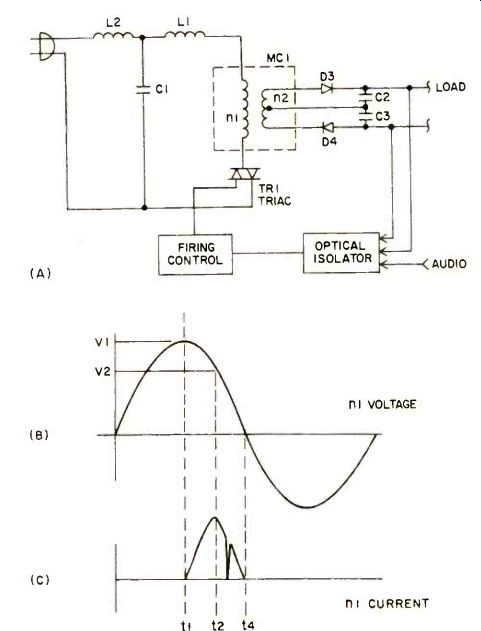
Fig. B1--Theory of operation of Magnetic Field Coil.
Referring to Figs. B1A, B1B and B1C, TR, is fired and turns on at time t1. Current flows into MC, from time t1 to time t2.
During this interval, current also flows in the secondary winding and charges C2 and C3 to voltage equal to V2 times the winding ratio of MC,. Since the output is clamped at ±80 volts by D3 and D4, C2 and C3, the difference between the reflected clamp voltage (V2) is: V2 = 80 (n1/n2). V, must appear, because of conservation of energy, somewhere. Ordinarily, the voltage drop (V1-V2) would appear as IR losses in the primary. However, by winding a magnetic shunt into the magnetic field coil (similar to a ferro-resonant transformer), a deliberate and controlled leakage inductance L1 is formed.
This causes V1-V2 to appear across L, in the form:
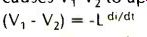
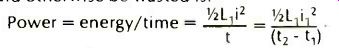
The energy associated with that quantity is stored in the field of L,. The amount of energy thus stored is'/ 1.1i2, where i is the current flowing at time t2. The amount of power that would otherwise be wasted is:
At time t2, the incoming 60-Hz line has fallen below the clamping voltage, hence D3 and D4 switch off. Once D3 and D4 are turned off, the tank circuit formed by L, (the leakage inductance) and C, (the commutating capacitor) begins to oscillate. However, since TR, commutates off as soon as its current passes through zero, only one half cycle of oscillation can take place. Once TR, has commutated off, the field surrounding L1 begins to collapse. Since the flux linkages of L, are common with n2 a flyback voltage appears on the secondary and causes D3 and D4 to switch on again, clamping the output to 80 volts. At time t4 current is no longer maintained by L1 since the stored energy has been transferred to the secondary of MC, and to the load. The same sequence of events takes place during the negative half of the input voltage cycle.
Commutator Details
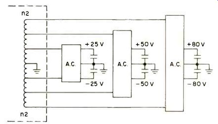
Fig B2--Detailed view of secondary taps of Magnetic Field Coil.
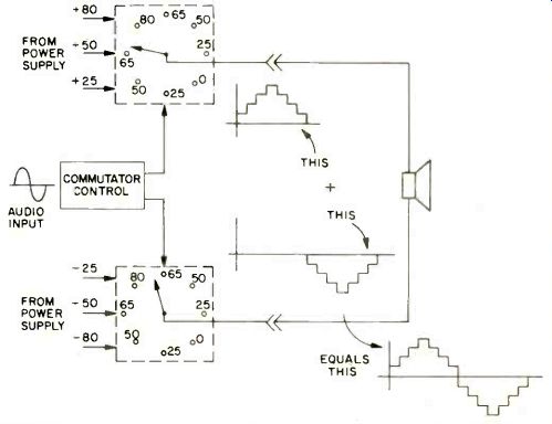
Fig. B3--Conceptual explanation of commutator action.
A more detailed circuit diagram of the power supply, as shown in Fig. B2, reveals that the secondary of the magnetic field coil has multiple taps which drive three full-wave bridge rectifiers to form six different levels of supply voltage: ± 25, ±50, and ±80 volts. A duty-cycle control circuit maintains these three voltage levels relatively constant, with some "softness" of regulation programmed into the system for good dynamic headroom of the amplifier. The output of these six voltage levels goes to the input of the commutator.
In concept, the commutator may be thought of as a rotary switch which is controlled by the input signal (or the output signal, since input and output are identical except for 30 dB of gain). The commutator delivers an output voltage that is a step-like approximation of the audio envelope, as illustrated in the diagram of Fig. B3.
The loudspeaker loads could be connected directly to the outputs of the commutators as shown in Fig. B3, but such an approach would obviously result in highly distorted sound reproduction. Furthermore, for signal levels between 0 and 25 volts, there would either be zero output or 25 volts of d.c. at the speaker! Consequently, the time-varying, conjugate-output voltages of the commutator go to a pair of complementary transistors, which may be thought of as a filter, to remove the steps, or as a small 15-watt amplifier whose B+ and B- supplies vary in level with the audio signal, as shown in Fig. 4. Note that this amplifier, composed of A1, Q1, Q2 and associated drive circuitry is a linear amplifier, biased so that both Q1 and Q2 con duct simultaneously for small signals. A conceptually complete block diagram of the entire Magnetic Field Amplifier is shown in Fig. B5.
As indicated in Fig. B5, there is an assortment of protective circuits all designed to make the amplifier as fail-safe as possible. Carver also supplied us with details and descriptions of how some of these protection circuits work.
The Clipping Detector
This circuit senses the presence of high-frequency components that occur during clipping. It will allow some clipping to occur, but if too much occurs for too long (and at too high a frequency content), the circuit will shut down the amplifier for a while. The circuit, detailed in Fig. 86, has two inputs: The input audio signal and the output audio signal from the amplifier. So long as the output follows the input, the output of the differential amplifier, A2, will be zero. If the output fails to follow the input because of clipping or overload, A2 will have an output that is then differentiated by C1R1 and peak rectified by D1C2. This positive d.c. voltage is then time integrated by D2C3. The voltage appearing at C3 represents the "stress history" imparted to the high-frequency driver during prolonged clipping. Too much clipping will cause the trip threshold to be exceeded, shutting off the supply.
Voice-Coil Temperature Integrator
Referring next to Fig. B7, this circuit represents a first-approximation analog of a high-fidelity loudspeaker's thermal properties. The audio output of the amplifier is rectified and filtered by D, and C1. Average voltage on C1 is related to the spectral energy distribution and to signal amplitude. C., charges through R1. The voltage on C2 represents, to a first approximation, the thermal stress history of the loudspeaker system, taken as a whole. The integral Vi dT, the volt-amp-time product, increases faster for high frequencies than for low frequencies. (Tweeters break down more easily than woofers, generally speaking.) The logarithmic junction of Q1 is used to get the product of v x i (power) delivered to the speaker.
Over-Current Trip Circuit
If too much current flows in the 0.1-ohm resistors in the output circuit, transistor Q1 in Fig. B8 turns on Q2 which trips the power supply. R1C1 serve as an integrating circuit (with an approximate time constant of 200 milliseconds) to prevent shut-down during very brief overloads.
Differential Low-Frequency Trip
Since the output of the left-channel amplifier is 180 degrees out of phase with the right channel (see Equipment Profile), in-phase signals at the input to the left and right channels will result in a small signal at Tp,. Out-of-phase signals, on the other hand, will produce a large signal at Tp,.
Accordingly, the low-frequency response at Tp, is small for (L+R) signal components, and large for (L-R) signal components. Response for high-frequency signals is virtually zero for both (L+R) and (L-R) signals because of the bypassing effect of C1.
A dropped tonearm, for example, will generate large (L-R) signals, whereas musical bass tones generate primarily (L+R) in-phase signals. Therefore, a low-frequency shutdown is arranged so that it will allow high-power, low-frequency musical signals to pass through, but will shut down for high-power, low-frequency faults.
Additional blocks shown in Fig. B5 but not fully described here are a d.c. fault trip, an over-temperature trip (a simple thermal switch on the chassis) and a circuit which is a voice-coil over-temperature trip, the details of which Mr. Carver asked me not to divulge.
Basic Shutdown Circuitry
While several fault types will cause circuit shutdown, the shutdown circuitry itself is illustrated in Fig. B9. When a "trip command" reaches amplifier A, (for whatever reason and from whatever fault detection circuit), its output goes high in voltage, turning on Q1 and charging C1. Q2 turns on and discharges the power supply capacitors through R1 and the LED that shines in the vicinity of the LDR. The R2C1 time constant determines the minimum amount of time that the power supply can remain in the shutdown state. Once the power supply capacitors discharge, the power supply will come on again. If one of the trip lines to Al is still high, the power supply will try to come on again but will turn off almost immediately (in about 20 milliseconds) after rising in voltage only slightly.
It should be clear from all of the above that the Carver Magnetic Field Amplifier is an extremely sophisticated piece of audio equipment that, despite its long gestation period, has left little to chance insofar as long-term reliability is concerned.
-L.F.
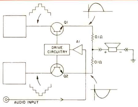
Fig. B4--"Filter" amplifier translates step waveform into replica
of audio input.
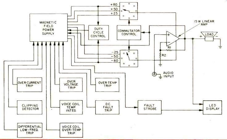
Fig. B5--Block diagram of Carver Magnetic Field Amplifier.
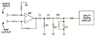
Fig. B6--Clipping detector circuit.
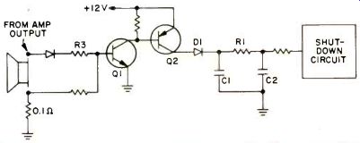
Fig. B7--Voice-coil temperature integrating circuit
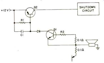
Fig. B8--Overcurrent trip circuit.
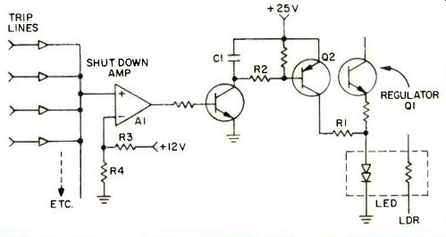
Fig. B9--Shutdown circuit.
=================
(Source: Audio magazine, Nov. 1980)
Also see:
Carver Compact Disc Player (Ad, March 1985)
Carver TX-11 FM Stereo Tuner (Dec. 1982)
= = = =