Manufacturer's Specifications:
TPT 3001A Tuner
(Note: All specifications are listed for wide/normal/narrow i.f. settings.)
Usable Sensitivity, Mono: 7.5/6.8/ 8.2 dBf.
50-dB Quieting Sensitivity: Mono, 11.3/10.3/9.3 dBf; stereo, 32.1/32.1/ 32.1 dBf.
S/N at 65 dBf: Mono, 95/95/95 dB; stereo, 82/82/82 dB.
Muting Threshold: 1 µV to 3 mV, variable (all i.f. bandwidth settings).
Stereo Threshold: 5 µV (all i.f. bandwidth settings).
Frequency Response: Mono and stereo, 30 Hz to 15 kHz, + 0.2,-0.5 dB, all i.f. bandwidth settings.
Distortion at 65 dBf, Mono: 0.03%/0.06%/0.12% at 100 Hz; 0.03%/0.06%/0.25% at 1 kHz; 0.03%/0.06%/0.45% at 6 kHz.
Distortion at 65 dBf, Stereo: 0.04%/0.05%/0.08% at 100 Hz; 0.04%/0.05%/0.2% at 1 kHz; 0.1%/0.25%/1.0% at 6 kHz.
IM Distortion: Mono, 0.1%/0.15%/0.5%; stereo, 0.1%/0.15%/0.8%.
Capture Ratio: 0.4/1.0/3.0 dB.
Adjacent Channel Selectivity: 3/ 12/40 dB.
Alternate Channel Selectivity: 30/90/90 dB.
AM Suppression: 70 dB (all i.f. bandwidth settings).
I.f. Rejection: 135 dB (all i.f. bandwidth settings).
Spurious Response Rejection: 135 dB (all i.f. bandwidth settings).
Stereo Separation: 60/60/55 dB at 100 Hz; 70/60/55 dB at 1 kHz; 50/45/ 35 dB at 10 kHz.
Subcarrier Product Rejection: 95 dB (all i.f. bandwidth settings).
Power Consumption: 34 watts.
Dimensions: 17 1/4 in. (43.5 cm) W x 13 3/4 in. (35 cm) D x 3 1/4 in. (8.3 cm) H.
Weight: 15.3 lbs. (7 kg).
Price: $1,195.00.
TIA 3012 Integrated Amplifier
Power Output: 100 watts continuous average power per channel, 8 ohm loads, 20 Hz to 20 kHz.
Rated THD: 0.02%.
Dynamic Headroom: 0.35 dB.
Frequency Response: Linear inputs, 5 Hz to 100 kHz, + 0,-3 dB; MM and MC phono inputs, RIAA 20 Hz to 20 kHz, ±0.2 dB. Input Sensitivity: MC phono, 16 µV; MM phono, 190 µV; high level, 15 mV. S/N: MC phono, 73 dB; MM phono, 78 dB; high level, 84 dB. Maximum Input Signal: MC phono, 20 mV; MM phono, 250 mV; D.D. and AUX, greater than 20 V; tuner and tape, 5 V.
Dimensions: 17 1/8 in. (43.5 cm) W x 3 1/4 in. (8.3 cm) H x 13 3/4 in. (35 cm)
D. Weight: 22 lbs. (9.7 kg).
Price: $995.00.
Company Address: Labriola Court, Armonk, N.Y. 10504.
I had the good fortune of visiting the Tandberg factories in Norway a few years ago. During that factory-sponsored junket I was shown some magnificent prototypes of audio components, each of which had been painstakingly designed by Tandberg's dedicated staff of engineers. Those prototypes were later to become the 3000 series of components, of which the TPT 3001A tuner and the TIA 3012 integrated amplifier are the latest examples. Since these two units are so obviously made for each other, Audio's editors thought it would be a good idea to evaluate them as a pair, and I heartily agree. That's not to suggest for a moment that each of these magnificent examples of Scandinavian craftsmanship doesn't deserve its own detailed test report and analysis. The new 3001A tuner is, in my opinion, one of the finest FM tuners I have ever tested, while the 3012 integrated amplifier was obviously designed to take into account the demands of new and better program sources, such as Compact Discs. Further, it incorporates the latest thinking concerning the influence of components on ultimate sound quality, the desirability of eliminating protection circuitry components from the signal path, the superiority of MOSFET output devices and much, much more.
Tuner Layout
The front panel bespeaks the simple elegance typical of Tandberg products. At the upper left are eight small station preset buttons. Below these are a power switch and an output level control, plus a "Store Program" button. A small display area nearby shows either an F (for manual tuning on the main FM dial scale), a P (for programming a preset station) or a number from 1 to 8 (indicating which of the preset buttons has been depressed). The signal-strength meter just to the right is an auto-ranging type, providing accurate signal-strength readings in microvolts (across 75 ohms). If signal strength exceeds 1,000 µV, a light comes on, telling you to multiply all readings by 1,000. A second meter, just to the right of the signal-strength meter, serves either as a center-of-channel tuning indicator (top scale) or as a frequency meter (lower scale), when using the preselect mode of tuning. The manual frequency scale and dial pointer are further to the right, with a large, machined tuning knob to its right. Two indicator lights are located just below the left edge of the tuning dial. The first lights when approaching propercenter-tuning of a station, telling the user that the center-tune function of the dual-purpose meter is now operative. The second indicator is the usual stereo multiplex light.
Four pushbuttons below the main tuning dial handle mono/stereo selection, automatic noise-cancelling circuit activation, a.f.c. (which Tandberg prefers to call "Servo"), and muting on/off. A continuously variable muting control knob sets desired muting threshold over a very wide range.
Finally, a three-position bandwidth selector offers choices of wide, normal or narrow i.f. response to meet the precise requirements of any reception condition or environment.
The rear panel of the 3001A is equipped with a 75-ohm coaxial cable connection. Since there are no 300-ohm antenna terminals, Tandberg supplies a 75/300-ohm matching transformer for those who prefer to use 300-ohm twin-lead transmission lines. In addition to a fixed and a variable pair of audio output jacks, the rear panel also houses a pair of horizontal and vertical output jacks intended for connection to an oscilloscope for observation of multipath effects. A detector output jack delivers a signal ahead of any de emphasis network and ahead of the built-in multiplex decoder. It might find application in the future for some sort of four-channel decoding, should such discrete multi-channel broadcasting ever become a reality in this country. A three position de-emphasis selector switch (25, 50 or 75 µS), line fuseholder, and detachable power cord complete the rear panel layout.
Tuner Circuit Highlights
The varactor diodes used in the tuning circuitry of the 3001A are equivalent to an 8-gang tuning circuit. Dual-gate MOS-FETs are used in the r.f. and mixer stages. The pre tuning circuitry used for the eight station presets is based upon the voltage-synthesis principle combined with a fast analog servo loop, which Tandberg feels is a better approach to achieving high S/N ratios and frequency stability than the more familiar frequency synthesizing circuits.
The i.f. system includes phase-linear block filters and pure LC filters. Tandberg uses a decoder consisting of discrete components, rather than the usual single IC chip.
The chief advantage of their design is the great reduction in beats observed when treble tones are received in the stereo mode. Tandberg attributes this improvement in part, at least, to the use of C-MOS technology. An automatic noise cancelling circuit comes into play during weak signal reception, improving signal-to-noise ratios at the expense of stereo separation, which then drops to around 10 dB. The servo tuning system uses a type of frequency feedback to lock the tuning to station frequency after the incoming signal has been properly tuned in. This servo action is automatically disabled when you touch the tuning knob.
Tuner Measurements
I was actually able to measure a signal-to-noise ratio of 90 dB for this tuner in mono and 84 dB in stereo. I strongly suspect that these measurements were limited by my signal generator, since they are the highest (for mono) that I have ever read for any tuner. While signal-to-noise characteristics did not vary much as I switched from wide, through normal, to narrow i.f. bandwidth, distortion did increase as I switched to the narrower bandwidths, as is to be expected.
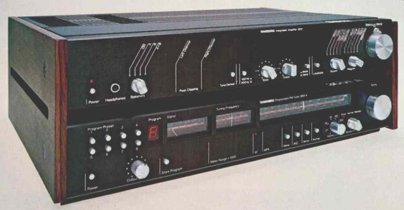
Plots of noise and distortion versus signal input for mono operation are shown in Fig. 1, while stereo performance with respect to noise and mid-frequency distortion is plotted in Fig. 2, for the sake of clarity. In the wideband mode, I measured the lowest distortion I have ever recorded for any tuner: 0.02% in mono and 0.03% in stereo for a 1-kHz modulating test signal. While distortion rose when I switched to the narrow bandwidth setting, it was still quite acceptable, with readings of 0.25% in mono and 0.35% in stereo for a 1-kHz test signal.
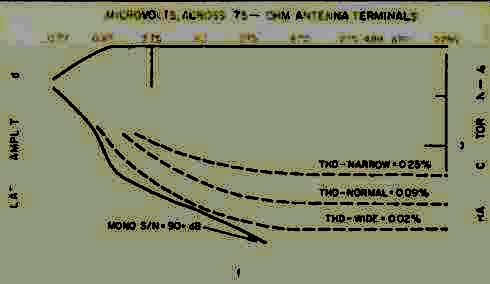
Fig. 1--FM quieting and distortion characteristics, monophonic mode.
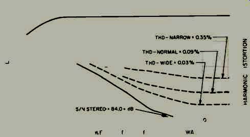
Fig. 2--FM quieting and distortion characteristics, stereo mode.
Fig. 3--Distortion vs. frequency, TPT-3001 A tuner.
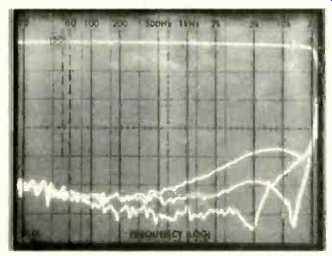
Fig. 4--Tuner frequency response and stereo separation.
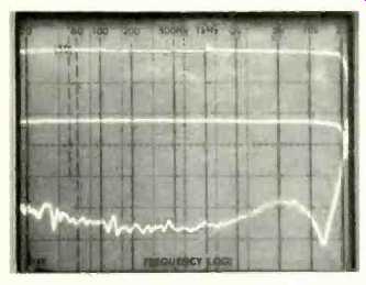
Fig. 5--Action of automatic noise cancelling circuit. Center curve is separation
with noise-canceller activated.
More significant differences in tuner performance show up when a high-frequency modulating signal is used (see Fig. 3). With a 6-kHz modulating signal, THD in the stereo mode measured only 0.06% in the wide setting, but increased to 0.5% when the bandwidth was switched to the narrow mode. That, however, is still far better than I often measure for tuners having only one bandwidth setting. Bear in mind, too, that in the narrow setting it is actually possible to separate stations that are only a single channel (200 kHz) apart, thanks to the high adjacent-channel selectivity, which I measured at 42 dB as against Tandberg's 40 dB claim.
Figure 4 is a spectrum-analysis multiple-sweep 'scope photo in which the upper trace represents frequency response of the desired, modulated stereo channel, while the three lower curves show separation versus frequency. As you might have guessed, the highest separation (lowest trace on the photo) was achieved with the wide setting, with somewhat poorer separation occurring in the normal mode and some further decrease in separation (particularly at the higher frequencies) occurring in the narrow-bandwidth setting. In the wide-bandwidth mode, I measured a separation of 62 dB at mid-frequencies, 50 dB at 100 Hz, and 48 dB at 10 kHz. Figure 5 shows what happens when signal levels are decreased sufficiently for the automatic noise-cancelling circuit to take over. The lower curve is identical to that obtained for the normal bandwidth setting shown in Fig. 4, while the curve midway between the desired channel output response and the normal separation shows the sacrifice in separation that occurs when this noise-cancelling circuit is operating. Typically conservative, Tandberg stated that separation would be reduced to something around 10 dB. In fact, separation remained greater than 20 dB (my 'scope photos here have a vertical sensitivity scale of 10 dB per division). Furthermore, unlike many simple blend circuits (which this definitely is not), channel separation remains virtually constant over the entire frequency range from 30 Hz to 15 kHz.
Figures 6.and 7 show crosstalk and distortion products observed at the output of the unmodulated right channel when a 5-kHz signal is used to modulate the left channel 100%. In Fig. 6, the tuner was set to its wide-bandwidth mode, while in Fig. 7, the narrow setting was employed.
These two photos demonstrate most dramatically, I think, the advantages of using a wideband tuner where reception circumstances permit. The undesired crosstalk and distortion products emanating from the output of the unmodulated channel are often audible since they are not masked by other sounds coming from that same loudspeaker when the primary program content is coming from the opposite channel.
Trying to measure capture ratio while in the wide mode was next to impossible. When capture ratio gets this low, I find that I have difficulty getting the same results twice in a row. Suffice it to say that capture ratio under those conditions was well under 1.0 dB, though I was able to confirm a consistent 1.0 dB for the normal mode and a 2.8 dB figure for the narrow mode.
I measured AM suppression slightly higher than the 70 dB claimed by Tandberg, as high as I have ever measured for any tuner. As usual, I could not confirm the claim of 135 dB for i.f., image and spurious response rejection, since 100 dB is about the best I can measure in my lab. Nor could I confirm subcarrier product rejection, except to say that it was superb, and below the 84 dB noise floor imposed by my signal generator. SCA rejection was better than 70 dB. As for sensitivity, I suspect that the matching transformer supplied by Tandberg introduces a couple of dB of loss.
Unfortunately, since my generator has a 50-ohm output and is coupled to a 50/300-ohm transformer, it was necessary to use Tandberg's 300/75-ohm transformer to get a correct match to their antenna connector. As a result, I was unable to precisely verify sensitivity and 50-dB quieting figures. I can state, however, that if you allow about 2 to 3 dB for transformer losses, Tandberg's figures come out right on the money. Of course, once full limiting is achieved, the slight amount of loss induced by those transformers becomes negligible, so you can take Figs. 1 and 2 as being essentially accurate above around 15 dBf.
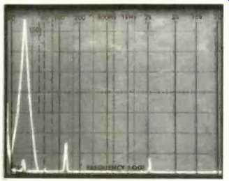
Fig. 6--Crosstalk for a 5-kHz modulating signal, wide i.f.-bandwidth setting.
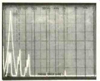
Fig.-7--Crosstalk for a 5-kHz modulating signal, narrow i.f.-bandwidth setting.
Amplifier Layout
The front panel layout of Tandberg's 3012 integrated amplifier blends nicely with the 3001A tuner. The on/off power switch and a headphone jack are located at the left, with a four-position rotary speaker-selector knob nearby.
Further to the right are a pair of peak clipping indicators, one for each channel. A tone control defeat button comes next, followed by a bass turnover selector (100 or 200 Hz), the bass control itself, a treble control, a treble turnover selector (3 or 6 kHz), and a loudness control button. Separate five-position record and program selector knobs come next, allowing the user to record one program source while listening to another. At the extreme right are concentrically mounted balance and volume controls.
The rear panel of this amplifier is equipped with the usual array of input and tape output jacks. Two tape monitor circuits are provided. Separate pairs of jacks for MM and MC phono cartridges are located at the extreme left of the rear panel, together with chassis ground terminals. There is no front-panel switch to select the correct (MM or MC) phono preamp circuit. Color-coded binding posts are supplied for two pairs of speaker systems; switched and unswitched convenience a.c. receptacles, a line fuseholder, and a detachable power cord make up the balance of the rear panel layout.
Amplifier Circuit Highlights
Tandberg's engineers, in a white paper issued recently, discussed the design philosophy behind this newest amplifier of theirs. They cited a series of design steps and features which they feel distinguish this amplifier from other units which might offer similar or identical bench measurements.
Because MOS-FET power transistors are used in the 3012, there is no need for current or voltage limiting of the output, and therefore, the 3012 is very suitable for use with electrostatic speakers, which often trigger such limiting devices and cause audible distortion.
Direct current must never be allowed to appear at an amplifier's output. In the 3012, d.c. voltage is controlled by Tandberg's new "Thermic Servo Loop" (pat. pend.), which utilizes heat-difference sensing devices to detect d.c. offset voltage and to adjust operating parameters so as to eliminate any d.c. voltage at the output. This system, unlike any other, has no direct connection to the audio signal path and therefore it cannot degrade sound quality.
The tone control circuitry of the 3012 is passive, with 1% calibrated resistors providing 2-dB steps and switchable turnover; these controls can be totally bypassed. The loudness compensation function increases bass response by up to 6 dB at low volume settings. The phono preamplifiers employ semi-passive RIAA equalization and conform with the new recommendations for phono equalization of IEC Amendment 4, 1976, specifying a roll-off of at least 12 dB per octave below 20 Hz. There are very good reasons for this modified equalization curve since part of the signal of a phono cartridge is produced by record warps and center hole offset, and such signals in the infrasonic region carry no music program information. They can, however, load down a power amplifier, limit its usable output power, and cause in-band intermodulation products which are audible.
In addition to causing problems within the amplifier's power stages, the infrasonic content of this cartridge signal has a tendency to force the woofer's voice-coil out of its linear operating region, causing increased intermodulation and harmonic distortion. The addition of an infrasonic (or subsonic) filter avoids these problems.
The MC and MM sections of the 3012 have three stages. First, there is a linear stage with moderate gain, to optimize the signal-to-noise ratio and overload margin. This is followed by the 18 dB/octave subsonic filter. Finally, a passive 75-1S RIAA treble equalization section, followed by an amplifier with active RIAA bass and midrange equalization, completes the system. The first linear stage is automatically matched to the MM or MC cartridge. It has a low impedance push-pull output to minimize distortion and effectively drive the subsonic filter which follows. The high-level tuner and tape inputs have separate input buffers with low-impedance push-pull outputs to prevent crosstalk or bleed-through from one program source to another. The special digital-disc input, however, has no amplification at all before the volume control and power amplifier. Furthermore, it can handle the extremely high input signal levels such as are likely to occur with digital program sources having extremely high dynamic ranges.
Amplifier Measurements
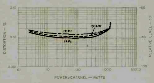
Fig. 8--Power output vs. THD, TIA 3012 amplifier.
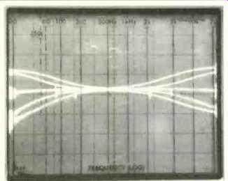
Fig. 9--Tone control characteristics.
The 3012 delivered just under 109 watts of power per channel at mid-frequencies into an 8-ohm load for its rated THD of 0.02%. At 20 kHz, output for this level of THD reached 106 watts while at 20 Hz, the amplifier delivered just a bit over its rated 100 watts per channel. The stiff power supply did, indeed, limit dynamic headroom, but I measured a full 1.0 dB for this parameter as opposed to Tandberg's conservative claim of only 0.35 dB. Figure 8 is a graphic plot of power output versus distortion for 20 Hz, 1kHz and 20-kHz test signals. CCIF (twin tone) IM measured a negligible 0.0086%, while IHF-IM was less than 0.01% (the lowest level I am able to detect using my spectrum analyzer, which has a dynamic range of 80 dB). SMPTE-IM measured 0.06% at rated output and decreased rapidly at lower power output levels.
Overall frequency response, using the high-level inputs, extended from 3 Hz to 105 kHz for the -3 dB cutoff points and from 6 Hz to 55 kHz for a -1 dB roll-off. My own inverse RIAA filter does not incorporate the new IEC subsonic roll off characteristic As a result, though the phono response was absolutely flat (to within 0.1 dB) above 100 Hz and all the way out to 20 kHz, I did measure a deviation of-0.7 dB at 30 Hz, which is just about what you'd expect when a preamplifier employs the modified IEC version of the RIAA curve.
Input sensitivity measured 0.17 mV for the MM phono inputs, 15 uV for the MC inputs, and 16 mV for the high level inputs. I should point out that Tandberg is one of a very few companies that conforms in every last detail to the EIA standards for specifying amplifier performance. I don't have to apologize, therefore, for any difference in reference levels between my readings and their published specs; they are one and the same, making it simple to compare their claims with my measured results. Other companies who continue to ignore these standards, please take note! Signal-to-noise measurements turned out to be consistently better than claimed. I measured 83 dB for the MM phono inputs, 79 dB for the MC inputs, 84 dB (as claimed) for the high level inputs, and 91 dB for minimum settings of the volume control. All S/N measurements are with respect to 1-watt output levels. The carefully configured tone control characteristics are shown in the multiple frequency sweeps of the spectrum analyzer display in Fig. 9. Loudness control action was extremely minimal and affected only bass tones.
Use and Listening Tests
At a recent digital audio seminar which I presented, the Tandberg 3012 integrated amplifier was specifically chosen by the management of the audio dealership as the amplifier to use when demonstrating Compact Discs. Having now had an opportunity to listen extensively to this remarkable amplifier, I can see why that choice was made. The amp delivers an open sound that is ideally suited to the new, noise-free, wide dynamic range Compact Discs. Where I disagreed with the recording engineers' ideas of sweetening, the simple but versatile tone control arrangement on the 3012 allowed me to adjust tonal balance without upsetting half the audio spectrum. Certainly, there may be instances where 100 watts per channel will not be enough to handle the dynamics of CDs (especially if you own an inefficient set of loudspeakers, as I do), but so long as you keep levels below clipping (the 3012 warns you about this with a reliable indicator for each channel), you're not likely to find an integrated amplifier that delivers cleaner, more accurate sound. Tandberg has never been known as a company that grinds out new models year after year, in a big hurry. In the case of the 3012, the long gestation period was justified. It's a top-performing amplifier well worth its price.
As for the 3001A tuner, here the answers are not all that simple. I think $1,195.00 is a lot of money to pay for any FM tuner--especially when there are some superb FM tuners around which sell for less than half that price (Sony, Carver and NAD, to name just a few). Certainly, the Tandberg has a few more things going for it than any of the above-named lower cost tuners, but the question is, will these extra features result in audibly better FM reception or sound quality? Are there enough high-quality FM stations around to justify such an expenditure? I asked these questions of Joel Rosenblatt, Director of Sales and Marketing for Tandberg, and, as is typical of Tandberg people, he gave me a very honest answer, with absolutely no hype attached. He pointed out that a Mercedes or a Rolls-Royce can't get you through rush-hour traffic any faster than a lower cost automobile and yet, as he put it, there are some people who just have to have the best there is, no matter what it costs, even if there's no way to avail themselves of all its inherent benefits. Evidently enough people feel that way about this new tuner to make it worthwhile for Tandberg to produce and sell it.
Being a dedicated FM listener, I wouldn't mind owning one of these Norwegian tuner masterpieces myself. I'm willing to wait until station practice catches up with it!
-Leonard Feldman
(Source: Audio magazine, Nov. 1983)
Also see: Tandberg TCA 3018A Preamp and TPA 3026A Amp (Apr. 1987)
Tandberg 3080A FM Receiver (July 1989)
Tandberg 3008A Preamp and 3009A Amp (Jan. 1986)
= = = =