by F. ALTON EVEREST
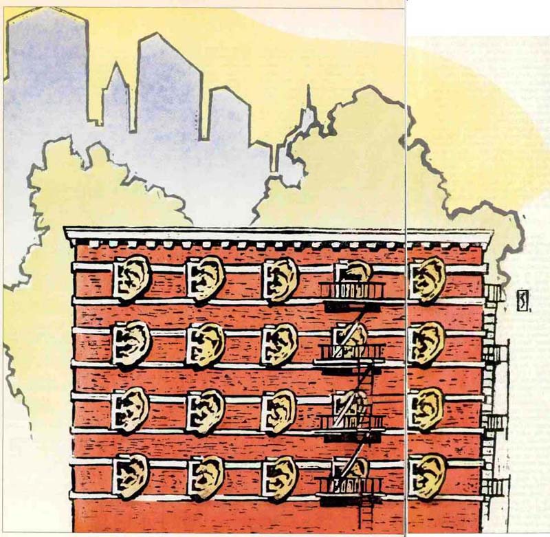
Living in an apartment or condominium means living close to neighbors. Though we may not even know their names, those living next door often inject themselves into our lives. Their daily noises aggravate us like the smell of their stir-fry seeping into the hallways. Exasperating as such things are, when my low Brahms passages are profaned by a cacophony of drum sounds from the loudspeaker in the next apartment, I become a raging hawk in the party-wall battle.
Consternation leads to disgust as one realizes how this whole problem could so easily have been solved as the apartment building was erected. It is all too easy to point a finger at the architect. He or she may merely have conformed to inadequate local building codes. Another possibility is that poor workmanship ruined a good design. But the increased cost of an effective wall is extremely small, so the cost argument evaporates.
What is initially important is a good design followed by adequate supervision to assure that .the design is implemented to the most minute detail. Ignorance and distorted ideas of economy are the basic reasons for the poor sound insulation prevalent in so many apartments and condominiums today. As we dig into the problem, we shall see that corrective procedures are both messy and costly.
What follows will provide an orderly introduction to the subject of sound leakage from one apartment to the next.
This is not a "do these ten things and the problem is solved" approach. Rather, it is a logical consideration of the factors involved. Once these factors are understood, the solutions to specific sound intrusion problems become evident.
GO TO THE SOURCE
In any noise-reduction problem, the acoustics consultant always asks what can be done at the source. The bothersome heel taps upstairs may be cured by a carpet. The noise of a business machine may be reduced to acceptable levels simply by putting an inch thick felt pad under it. Why tear up the place if such a simple approach will solve the problem? If the neighbor's stereo is too loud in your apartment, it is possible that the neighbor would be cooperative enough to lower the volume to an acceptable level. But this is not acoustics, it's "psycho"-acoustics. It presupposes a kid-gloves approach and a cooperative neighbor, but it is worth considering because it is the fastest and the cheapest solution. It is also a two-way street: You may be asked to lower the volume of your own stereo.
Establishing a friendly relationship with your neighbor is not only the human thing to do, but it may also increase the neighbor's tolerance of you if you must do a lot of hammering as an alternate solution.
IT'S A THREE-PART PROBLEM
The annoyance a neighbor's noise creates in your apartment depends on three things-the level of the neighbor's sound in his apartment, the transmission loss of the party wall, and the background noise in your own apartment. The overall annoyance, of course, is a combination of all three effects. Before you tackle beefing up the wall, for example, it would be well to consider the first and third items.
Undoubtedly you have already formed some pretty strong opinions on the excessive volume of the neighbor's stereo system and the deficiencies of the party wall, but the background noise level in your own apartment determines whether a given intruding noise is annoying or not. If you live in a very quiet apartment, you may be disturbed by almost every sound, even if the wall is a good one. If your own household noises are louder, they will tend to mask intruding noises. If your stereo is played often, you may not hear your neighbor, but your neighbor may hear you. Table I lists some common background-noise levels in "noise criteria" (NC) and in dBA relative to the threshold of hearing.
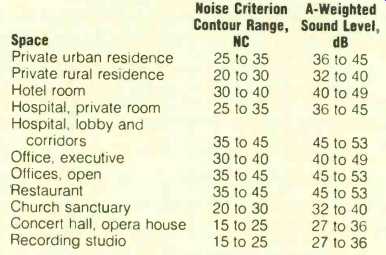
TABLE I--Common background-noise levels for typical spaces, measured with
all heating, ventilating, and air-conditioning equipment running [2].
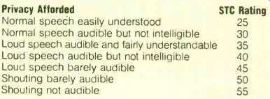
TABLE II--Criteria for roughly estimating sound transmission class of
a party wall [4].
ESTIMATING PARTY-WALL EFFECTIVENESS
Only when we are able to put some numbers to it are we in any position to move on to a solution of the party-wall problem. The industry has adopted the concept of Sound Transmission Class (STC) to reduce to a single-number rating all the complicated factors involved in the attenuation of sound as it passes through a wall [1]. Of course, such a single number rating is a compromise, but it is convenient, practical, and accurate enough for our purposes.
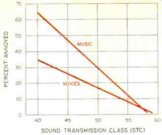
Fig. 1--Relative annoyance values of music and speech for various party-wall sound transmission classes, based on a survey of 100 apartments by Bradley [2].
Bradley's study of 100 apartment dwellers and the 50 party walls between them has shown that the annoyance resulting from music and speech in the next apartment is related to the STC of the party wall, as can be seen in Fig. 1 [2]. His study also shows that people are far more sensitive to neighbors' music than to their speech.
To illustrate just how the Sound Transmission Class of a partition is determined, actual measurements on a common type of wall construction are shown in Fig. 2. The transmission loss of the wall, measured at third-octave intervals, is poor at low frequencies but improves at the higher frequencies in a rather erratic way. Fortunately, the poor sensitivity of the human ear tends to compensate for low transmission loss of walls at the low frequencies.
The standard STC contour, made up of three straight lines, is also shown in Fig. 2. The general procedure is to plot the STC contour on tracing paper to the same scales as the graph of measured values of transmission loss. The tracing is placed over the measured graph with the frequency scales coinciding. Neglecting all measured points above it, the STC contour is moved up and down until the measured points below the STC curve reach a certain standard limit. (This is defined in [1]. If you are interested in the process, see [3] for a step-by-step determination of STC.) The single-number STC rating for this particular measured transmission loss graph is read off at 500 Hz.
The partition of Fig. 2 is then said to be in the Sound Transmission Class of STC-44. This shorthand method of classifying complicated transmission loss curves is now used throughout the building trades. As a very rough indication, you may think of a partition rated at STC-44 as giving approximately 44 dB of transmission loss at 500 Hz.
In this particular case, the measured transmission loss at 500 Hz is actually 46 dB. The transmission loss of partitions will generally be less than the STC single-figure rating below 500 Hz and greater above 500 Hz.
Right now we are interested in one partition only, and that is the party wall between you and your neighbor. What STC rating does it have? We could drag in a pink-noise generator, powerful amplifier, loudspeaker, and sound level meter and measure it at 1/3-octave points and make correction for the absorption in the receiving room, but that is a bit beyond our present purpose.
To get a very rough indication of that wall's performance, send someone into the room the noise is coming from and have them speak at various levels.
Then compare what you hear with the ratings in Table II. If your neighbor cooperates, you should be able to estimate the STC of your party wall. Remember that number while we consider other factors involved in sound transmission through walls.
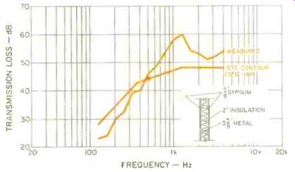
Fig. 2. Spectrum of noise transmission loss and sound transmission class
(STC 44) of a common type of wall construction (Kodaris Acoustical Labs).
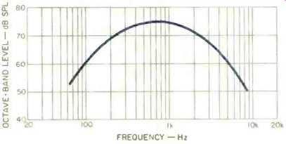
Fig. 3--Assumed spectrum of annoying music in adjacent apartment.
The level calculated from this spectrum is 71 dBA.
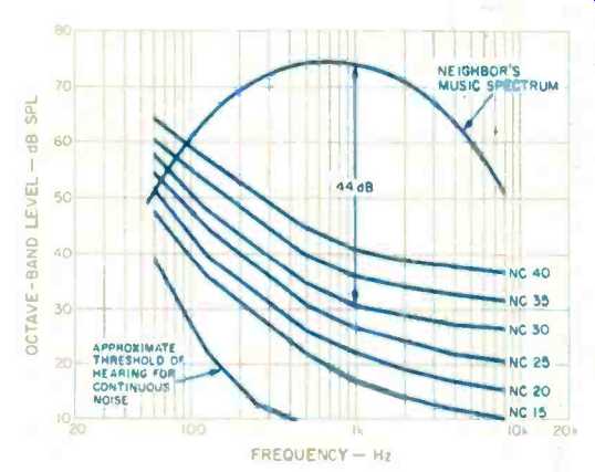
Fig. 4--Family of noise criteria (NC) contours commonly used to specify
background noise level in sound-sensitive spaces, plotted against music
spectrum of Fig. 3. To achieve an NC-311 contour in the listener's apartment
under these conditions, the party wall must provide 44 dB of transmission
loss at 1 kHz. The difference between the NC-30 contour and the noise spectrum
at each frequency determines the minimum performance of the party mall
required to reach NC-30.
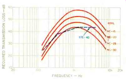
Fig. 5--Minimum transmission loss required of a party mall to reach various
noise criteria with the noise source of Fig. 3. In This case, a mall with
a sound transmission class of 40 is required to achieve NC-30.
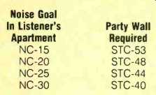
TABLE III--Party-wall attenuation requirements to meet various noise goals
for the example given in Fig. 5.
RELATING STC TO NOISE LEVELS
Let us assume that, on the neighbor's side of the party wall, the "noise" is a musical selection with the spectrum shown in Fig. 3. The sound level computed from this spectrum is 78 dBA, which is a rather low level. The energy falls off at low and high frequencies in a way that is characteristic of normal sounds.
To describe the background noise in your own apartment, we can use the NC concept. Like STC, noise criterion is a method of expressing a noise spectrum in a single NC number. Note that both the STC and the NC single numbers are approximate representations of spectra, taking advantage of the fact that background noise spectra tend to have similar shapes, as do transmission loss curves.
A family of NC curves is shown in Fig. 4. The general shape' of these curves takes into consideration not only the general spectrum shape, but also the human ear's lesser sensitivity to low-frequency sounds. Table I lists ranges of NC numbers applied to background noise in numerous real-life situations. The NC-15 curve would be a quite stringent background-noise goal for a professional recording studio. The NC-25 curve would represent about the highest background noise allowable in a public auditorium; the air-conditioning contractor might have to go to some pains to meet such a specification. As for your apartment, considering both household noises and the intrusion of environmental noise from the outside, NC-30 might be a reasonable point of departure.
The neighbor's spectrum from Fig. 3 has been added to Fig. 4 at its actual level. The neighbor's "noise" spectrum, as measured in the apartment next door, is 44 dB above the NC-30 contour at 1 kHz. Therefore, the party wall must attenuate the noise by 44 dB to reduce the 75-dB octave-band level at 1 kHz on the neighbor's side to the desired NC-30 contour in your apartment. Measuring the difference between the spectrum of the neighbor's "noise" and the NC-30 contour of Fig. 4 at other frequencies defines the minimum transmission loss required of the party wall. This has been done in Fig. 5, not only for the NC-30 contour but for three lower NC contours as well.
The curve labeled NC-30 in Fig. 5 defines the attenuation required of the party wall between the two apartments.
The dashed STC contour, which is fitted to the NC-30 attenuation-required curve according to standard rules, reads 40 dB at 500 Hz, or STC40. An STC-40 wall, which is easily achieved, is all that would be required to attenuate the 78 dBA music in the neighbor's apartment to the NC-30 contour in your own apartment. Louder music would require a heavier wall.
A lower NC in your apartment would also require a heavier wall, even for this relatively quiet music. Party-wall attenuation requirements for NC-25, NC-20, and NC-15 are also shown in Fig. 5. Fitting the STC line to each of these yields the STC wall ratings shown in Table III. And this is for a relatively quiet "noise" on the neighbor's side (78 dBA for music). We must avoid the temptation to add ten STC points if a neighbor's music level is 10 dB higher. It is necessary to go through all these steps to take into proper consideration the spectral distribution of energy in the neighbor's music and the background noise in our apartment, as well as the variation of wall transmission loss with frequency.
SOUND PATHS
By this time, as a result of our yelling, we have formed some idea of the STC of the existing party wall (Table II). In addition to that we now have a better feel for the relationship between wall STC and noise levels on both sides of the wall (Figs. 1 to 5). Now we will consider the myriad ways sound travels from one apartment to the other.
Sound travelling through air seems quite natural, but sound travels through solid structures as well. Solid paths between our apartment and neighboring spaces are illustrated in Fig. 6. The solid arrows labeled D represent sound that travels directly through a wall that is subject to a transmission loss already considered. Walls are commonly made up of wood or metal studs with sheets of drywall (also called plasterboard, gypsum board, or sheetrock) or other materials on each side. The sound in a room causes the drywall panels to vibrate as diaphragms. Some of the energy in the vibrating panel on one side is transmitted to the diaphragm on the other side directly through the studs. Vibrating diaphragm energy also sets the air in the cavity between the two wall faces to vibrating, which, in turn, excites the opposite diaphragm. Both airborne and structure-borne sound are thus involved in this process.
The broken arrows and lines of Fig. 6 represent sound that travels through the structure itself. Such solid-borne sound travelling to adjacent rooms is usually not a direct threat. The problem arises when the solid-borne sound sets large wall diaphragms to vibrating and radiating sound in adjacent rooms with relatively high efficiency.
I will never forget a visit to a newly constructed, multi-million-dollar radio studio. Inside one of the studios a distinct hammering sound was clearly audible. The embarrassed host engineer explained that the hammering was quite far from the studio. They had been sure to insulate the studios from the noise of aircraft on a nearby approach path, but they had not provided for suitable isolation from structure borne noise within the building. Structure-borne sound is a reality, coupling our listening space to distant events such as heel taps, plumbing pipe noises, and elevator sounds, as well as the neighbor's stereo. The level of such sounds is often lower than the sound that comes through the party wall.
Figure 6 is a plan view. The elevation view of Fig. 7 suggests other flanking paths that may involve both airborne and structure-borne paths. Sound can readily travel from one apartment to another through an "attic" space above the ceiling or crawlspace beneath the floor. Solid barriers at positions A and B of Fig. 7 are required to minimize the effect of such unwanted paths.
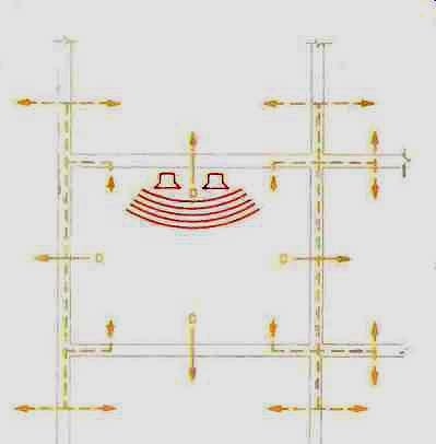
Fig. 6--Plan view showing direct sound-transmission paths (solid arrows)
and flanking paths (dashed arrows).
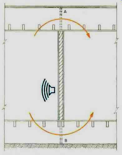
Fig. 7--Sound transmission between rooms or apartments in flanking paths
above the ceiling or beneath the floor. Solid barriers at points A and
B are required to block such paths.
Sound can travel from one apartment to another through heating ducts acting like speaking tubes. This can be reduced by increasing the length of ducting between apartments, using ducts with absorbent linings, increasing the number of bends, or installing noise-reducing plenums.
SOUND LEAKAGE
The tiniest hole or crack can ruin the insulating effect of an otherwise good party wall. Cracks at the floor line are notorious in this regard. The 2 x 4-inch plate or steel runner that rests on the structural floor invariably makes poor contact due to the floor's rough texture.
In new construction, an excellent acoustical precaution would be to set this plate or runner in non-hardening acoustical sealant. Using ordinary mastic is not an answer because, when it hardens, it tends to pull away from the surfaces it should seal.
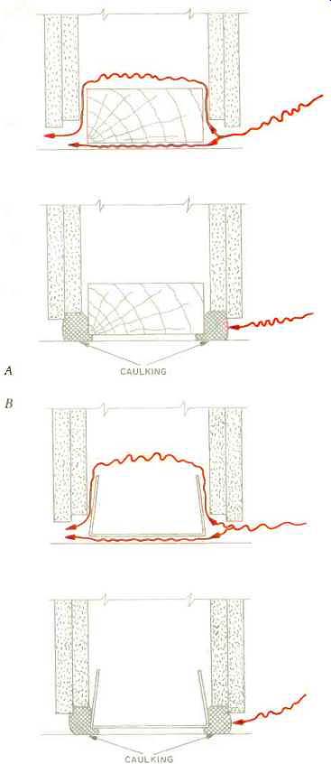
Fig. 8--Plan view showing common leakage paths through party walls using
wood studs (A) and steel studs (B). Caulking with non-hardening sealant
stops such leaks.
Figure 8A illustrates the problem with walls resting on 2 x 4-inch wood plates. Sound may leak between the drywall and the plate as well as under the plate. A generous, running bead of acoustical sealant on both sides of the wall, as shown, will eliminate this source of leakage sound. A similar situation exists for steel runner track for steel-stud construction, as shown in Fig. 8B. Rolling the carpet back and introducing beads of sealant on each side of a party wall will take care of sound leaking under it. Similar possibilities of leakage exist around the rest of the periphery of the walls. Beads of acoustical sealant along the vertical joints as well as at the ceiling will help to assure tightness.
Electrical service boxes in the party wall should receive a critical inspection. An especially weak condition would result if such boxes were back to back. Look for crevices and holes in the boxes, which should be daubed with sealant. Conduits running between the two wall faces can be neutralized by ramming glass fiber tightly into each conduit between the wires. In eliminating sound leakage, the wall must be treated as though you were making the room airtight.
USE THOSE GOLDEN EARS
Audiophiles reading this are uniquely equipped to perform the next test.
After all, anyone who can detect the difference between 0.01% and 0.02% distortion and between $2 and $100 loudspeaker cables should be ideally suited to finding leaks in a party wall.
Seriously, an acute and trained human ear can tell a lot about how sound travels from the neighbor's apartment to your own. By careful listening, you may be able to tell whether the sound comes through the walls (the normal first assumption) or whether some flanking paths are involved. Check for sound leaks around the periphery of the wall and around electrical, television, and telephone service outlets. If flanking paths seem to be major contributors to the intruding sound from the next apartment, it may be an exercise in futility to strengthen the party wall. It may be wiser to go after the flanking paths.
IMPROVING THE PARTY WALL
You must consider wall constructions and their relationship to sound insulation. This is not only good information for solving existing noise intrusion problems but is also basic for new construction. Remember that the STC values to be considered are based on laboratory measurements. Great effort has been expended toward conforming measurements made at different laboratories or measurements made in the same laboratory at different times.
There may be internal inconsistencies of an STC point or two that should not be allowed to overshadow the fundamental principles being considered.
Figure 9 shows eight different wall constructions based on 2 x 4-inch wood studs spaced 16 inches on centers, each with its STC rating. Note that 2 1/2-inch glass fiberfill is specified for each of the eight. Construction A is all too commonly encountered in party walls-2 x 4-inch studs with a single layer of drywall, usually 1/2 inch, on each side. The rating is only STC-36, weak enough to result in real tenant annoyance if used between apartments. Adding other layers of drywall to this ubiquitous but deficient party wall will yield only minor increases in STC rating.
An entirely new principle is used in the construction shown in Fig. 9B. This is the staggered-stud method of avoiding direct connection between the facing on one side and that on the other side. With only a single layer of drywall on each side, we see a significant jump from STC-36 to STC-49, an increase of 13 points attributable solely to isolating one face of the wall from the other. In Fig. 9C we note that adding a second layer of drywall on one side of the staggered-stud construction adds only four points, to bring it to STC-53. More mass has been added, but there has been no change of design principle such as occurred between Figs. 9A and 9B. The construction of Fig. 9D, with double drywall on both sides of the staggered-stud wall, increases the rating only another three points, to STC-56. We conclude that doubling the mass on one side adds only three or four points.
While the construction of Fig. 9E goes back to the straight 2 x 4-inch stud wall, it still isolates one wall facing from the other. But rather than using staggered studs, it uses Z-shaped resilient channels to mount the double drywall facing on one side. This results in the same STC-56 rating as the staggered-stud construction of Fig. 9D. Figure 9F shows a double-wall construction, with two separate rows of studs on separate plates, spaced an inch or two apart. This complete separation of the two wall surfaces achieves an STC rating of 56 with only a single drywall surface on each side. In Figs. 9G and 9H, we find, once again, an increase of four points by doubling the drywall on one side and three more points by adding double drywall on the other side. Figs. 9B, 9C, and 9D constitute a staggered-stud family, Figs. 9F, 9G, and 9H a double-wall family. In either case, doubling the drywall layers on one side adds four STC points, and doubling the drywall layers on the other side adds only another three points.
The wall constructions of Fig. 9 run the gamut from STC-36 to STC-63 from deficient to excellent when used as party walls in apartments and evaluated on the basis of annoyance as in Fig. 1.
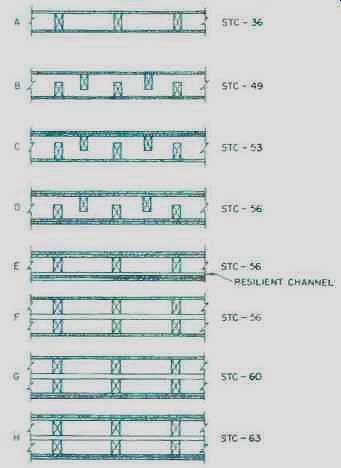
Fig. 9--Typical walls using 2 x 4-inch wood .studs spaced on 16-inch centers,
and the STC ratings for each. Note the great improvement in STC when the
two faces of the wall are decoupled from each other by the staggering of
studs (B, C, and D), the insertion of resilient channels (E), or double-wall
function (F, C, and H); [6]. All cases include 2 1/2 inch insulation (not
shown) between stud.
Figure 10 shows six wall constructions based on 3 5/8-inch steel studs spaced 24 inches on centers. It is fortunate that steel studs are widely used in new construction today because the stud itself introduces a modest degree of resiliency lacking in the wood 2 x 4.
In Fig. 10A, the STC rating is increased eight points by the addition of 2 1/2 inches of thermal insulation as fill.
This is greater than the three to five point improvement normally found when such insulation is added to wood-stud construction. This glass fiber serves to reduce the coupling between wall faces by discouraging the resonance of the air in the cavity.
Figure 10B tells us something about how much insulation fill should be used. The STC-47 is reduced to STC45 by jamming 4 inches of glass fiber into the 3 5/8-inch space. It is not wise to place too much value on the two-point difference, but it suggests that nothing is to be gained by adding more than the usual 2 1/2 inches of insulation into the cavity. It is possible that compressing the 4 inches of insulation introduces a slight direct coupling between the two faces of the wall, which accounts for the reduction of two STC points.
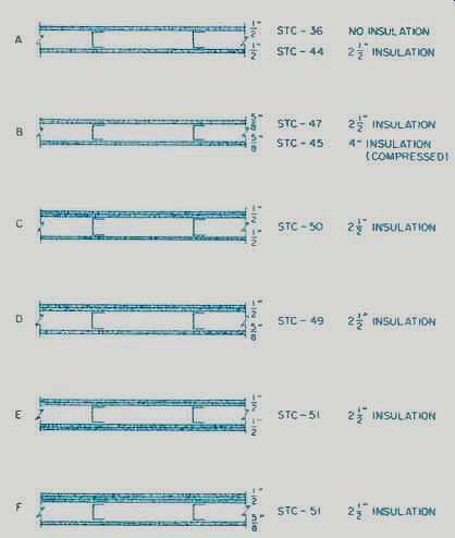
Fig. 10--Typical malls using sled studs on 2.1-inch centers, and STC ratings
for each. The resilience of steel studs tends to decouple the two faces
of the wall [6].
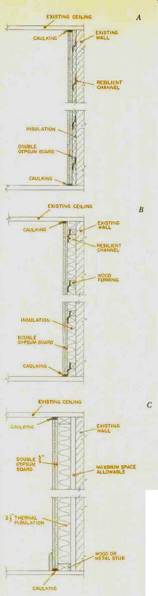
Fig. 11--Three approaches to strengthening an existing party wall, in
ascending order of effectiveness: Double drywall mounted on resilient Z-channels
(A): the same, with wood furring to increase the air gap (B): and double
wall for even greater air space and decoupling (C).
With various numbers of layers of drywall in the constructions of Figs. 10C through 10F, the ratings vary only between STC-49 and STC-51. This may or may not be sufficient for a party wall. If not, staggered-stud or double-wall techniques, or resilient Z-channels, may be called into play.
If investigation suggests the need to strengthen the party wall between you and the offending stereo noise in the next apartment, how does one go about it? In Fig. 11, three approaches are shown. If only a modest increase in party-wall transmission loss is needed, the wall supplement shown in Fig. 11A may be sufficient. In this case, two layers of drywall are added, but they are added resiliently by the use of Z channels. It would hardly be worthwhile adding the drywall directly to the existing wall, as this would add only three or four points to the existing STC. The air space provided by the Z-channels, while small, improves the low frequency absorption and should be filled with some thermal-type glass-fiber insulation.
A higher STC rating can be achieved with essentially the same labor and little additional materials by using the plan of Fig. 11B. Mounting the Z-channels on 2 x 2-inch wood furring strips increases the air space and thus the wall's transmission loss. The party-wall supplement of Fig. 11A is not recommended (it has been included only as an instructional first step); that of Fig. 11B has superior performance at essentially the same cost.
If the loss of space can be justified, the party-wall supplement shown in Fig. 11C should solve any problem attributable to sound transmission directly through the party wall. This construction makes the party wall a double wall and should yield an STC of 60 or thereabouts. Table I would tell us that shouting in the other room should not be audible in a room with such an improved party wall. Flanking paths, however, could very well become significant with such a wall supplement.
IMPROVING THE FLOOR/CEILING BOUNDARY
The tacit assumption, to this time, has been that only the walls are suspect if the neighbor's stereo bothers you. This assumption may not be valid.
You may annoy the tenants below or above you, or they may annoy you. The same principles we have considered for walls apply to floors and ceilings except that structure-borne sound may be more dominant.
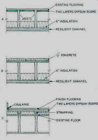
Fig. 12--Three approaches to strengthening the floor/ ceiling or ceiling/floor
boundaries of a room, requiring access to the ceiling alone (A), both
floor and ceiling (B), and floor alone (C).
The three constructions of Fig. 12 are arranged in order of progressively greater transmission loss. In Fig. 12A, it is assumed that there is no control over what happens above, that all changes must be made from below. A double layer of gypsum board is fitted between the joists and cemented to the subflooring. This increases the mass of the floor diaphragm. A 6-inch layer of thermal glass fiber is then introduced in the space between the joists. A second gypsum-board ceiling layer should then be supported by resilient Z-channels.
Figure 12B is the same as 12A on the lower portion, but changes have been made in the flooring. A 1 1/2-inch layer of lightweight concrete is poured on a subfloor of two layers of plywood.
The mass of the concrete makes a significant contribution to the transmission loss.
There is much interest in "floating floors." The concrete of Fig. 12B could have been poured on top of a proprietary glass-fiber layer, but the cost would have been much higher. Another possibility is to pour the concrete on a soft-fiber soundboard over which a plastic sheet has been laid.
In Fig. 12C, a less expensive (and somewhat less effective) floating floor is illustrated. A framework of wooden strapping rests resiliently on a layer of glass fiber. A double layer of gypsum board rests on the strapping and is topped by the finish flooring. It is imperative that no solid part of the floating structure makes contact with the existing floor or walls. An edging of denser glass fiber is one way of assuring this. Non-hardening sealant traps the air beneath the flooring so this air's springiness will be retained.
The density of the glass fiber on which the strapping of Fig. 12C rests is important. If it is too flimsy, the strapping will make solid contact with the existing floor. On the other hand, if too dense and hard, there will be little resilience and, again, a virtual solid contact will result. It is easy to build a floating floor but not so easy to design one that will perform properly. Floating floors require proper design to assure proper performance.
STC ratings are not normally applied to floor/ceiling structures. Instead, Impact Insulation Class IIC applies. This involves a standardized floor tapper as a sound source. However, the IIC ratings are not available.
PRACTICAL HINTS
Make sure you understand the importance of mass in building a barrier with high transmission loss. For example, if anyone suggests cementing a layer of carpet, acoustical tile, or other lightweight material on your party wall as a sound barrier, forget it. These techniques may be good for absorbing sound reflections, but, because of their low mass, they have little effect on stopping sound transmission.
The insulation in the wall cavity is not put there to stop sound. It is there to reduce the cavity resonance, which tends to couple the two faces and thus lower the transmission loss.
Drywall is a relatively inexpensive material with significant mass, and its use helps achieve high transmission loss and high STC ratings. Half-inch thick drywall is widely used in construction. When mass is needed, why not use 5/8-inch or even thicker drywall? The cost increase is modest, and the labor costs will be essentially the same.
As important as mass is in stopping sound, staggered-stud or double-stud walls far outperform mass alone.
The greater the air space between two wall surfaces, the greater the transmission loss of the wall, especially at low frequencies--and all walls need help in the low-frequency region.
Metal studs are better than wood studs in walls in which transmission loss is important. Metal studs are made of relatively flimsy steel, so they act as a sort of resilient channels. Therefore, less sound is transmitted from one wall face to the other.
Be sure to investigate potential flanking paths around a party wall. If they tend to dominate, there is little to be gained by strengthening the wall itself.
Be alert to the possibility of flanking paths through the windows of your and your neighbor's apartments, or by way of doors (or the cracks around their edges) and hallways.
If a neighbor's loudspeaker is resting on the bare floor or is otherwise in direct contact with the structure, flanking sound via the structure will be increased. Placing loudspeakers on a carpet, rug, or other resilient material will help.
While lightweight sound-absorptive materials will not block sound transmission (due to their low mass), they can still reduce unwanted sound levels slightly. By doubling the sound absorbents in your apartment, the level of all sound in your room will be reduced by 3 dB (which isn't much). If you then raise your stereo system's gain by 3 dB, a net signal-to-noise improvement of 3 dB (which again isn't much) will result. Of course, your room would probably then be too dead for your musical tastes, unless it was far too live to start with. Increasing room absorption is a very questionable way of reducing the effects of your neighbor's noise.
REFERENCES
1. Determination of Sound Transmission Class, American Society for Testing Materials, designation E413-701.
2. Bradley, J. S., Subjective Rating of the Sound Insulation of Party Walls--A Pilot Study, Division of Building Research, National Research Council of Canada, No. 196, October 1982.
3. Everest, F. Alton, "Common Factors in All Audio Rooms," Handbook for Sound Engineers--The New Audio Cyclopedia (Glen Ballou, editor), Howard W. Sams & Co., Indianapolis, Ind., 1987.
4. Warnock, A.C.C., How to Reduce Noise Transmission Between Homes (Apartments), Division of Building Research, National Research Council of Canada, Ottawa, No. 44, July 1983.
5. ASHRAE Handbook and Product Directory--1977, Chapter 7, "Sound and Vibration Control Fundamentals," American Society of HVAC Engineers, Inc., 345 East 47th St., New York.
6. Northwood, T. D., Transmission Loss of Plasterboard Walls. Division of Building Research, National Research Council of Canada, Ottawa, No. 66, October 1968, revised July 1970.
(adapted from Audio magazine, Nov. 1990)
Also see:
Earning a Deaf Ear: Loud Music & Hearing Loss (Jan. 1989)
Good Walls Make Good Neighbors (Dec. 1990)
The Mosaic Reissues: Standards of Excellence (Nov. 1990)
= = = =