By WILLIAM R. SHORT
[William R. Short is Principal Engineer of the research staff of Bose Corp., Framingham, Mass.]
Contemporary movie soundtracks often pack a tremendous wallop in the octave between 25 and 50 Hz. Because of speaker limitations and the extremely small amount of ordinary music that contains significant energy at such low frequencies, home playback systems are seldom capable of much output in that band. A well-equipped motion picture theater, on the other hand, can reproduce every growl, rumble, and explosion.
The Bose Cinema Sound System uses Bose's Acoustic Wave technology to meet the extraordinary sonic demands of today's films with loudspeakers that are smaller, more versatile, and easier to install than conventional designs.
The current method of recording sound optically on 35-mm motion picture film dates from the 1920s. Although there have been major improvements over the decades in film emulsions, and in practices and standards, the performance of a mono optical track is somewhat limited. A major improvement was made in the 1970s by the introduction of the Dolby Stereo system to the cinema.
The Dolby Stereo system is more than the familiar noise-reduction system applied to film. There is room for only two discrete soundtrack channels on 35-mm film. The Dolby cinema processor reads these two tracks off the film and applies Dolby A-type noise reduction. (Currently, Dolby SR noise reduction is being used more and more, instead of A-type, which provides further performance advantages ) The two tracks feed a decoder to generate the four channels which are reproduced in the theater.
(The left, center, and right speakers are placed behind the screen, while the surround channel is reproduced by many speakers on the side and rear walls.) In addition, the two tracks feed an optical bass-enhancement (OBE) circuit which cleans up the bass signal and sends it to a separate subwoofer output.
Finally, room equalization is provided on all four main channels and on the bass channel.
Most of this processing is familiar to audio enthusiasts. For example, the two-to-four-channel matrix is now widely used in home theater systems to generate the surround channel from home video releases, which frequently use the same two-channel mix as exists on 35-mm film. The one unusual processing step is the OBE circuit. Before describing how it works to clean up the low frequencies on film, let's look at why it is needed.
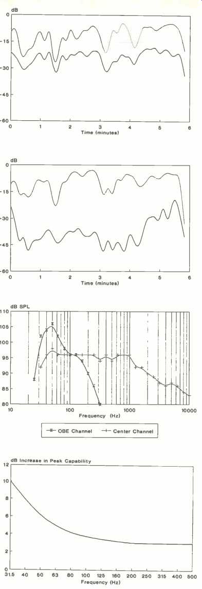
Fig. 1--Program level (top) and low-frequency noise level (bottom) for a clip from the 35-mm release print of Amadeus.
Fig. 2--Same as Fig. 1 but film clip is from videodisc.
Fig. 3-Peak level requirements for center and subwoofer channels, as measured from eleven Dolby Stereo 35-mm films.
Fig. 4--Additional peak level capability of films using Dolby SR noise reduction as compared to those using Dolby A NR.
Low-Frequency Noise on Film
Optical soundtracks on film can suffer from several sources of signal degradation. Many of these degradations result in the generation of low-frequency noise and distortion components.
Optical soundtracks inherently have cross-modulation distortion. This type of distortion results from nonlinearities in the film process and causes distortion products whose frequencies are the sum and difference of frequencies in the original audio source material.
The exposure and processing of both the original sound negative and of the release print are carefully controlled to minimize cross-modulation distortion at one frequency. However, a paper presented recently shows that optimizing the distortion at one frequency does not necessarily minimize it at all frequencies [1). Cross-modulation from mid- and high-frequency components can result in distortion products being created at low frequencies. As the level and content of the recorded audio change, the level of the low-frequency distortion products changes as well.
Low-frequency noise can also be generated by the single-ended noise-reduction system that is universally used while recording the original sound negative. This system takes advantage of the fact that opaque film is quieter than clear film. During recording, the d.c. level of the audio is dynamically shifted so as to minimize the amount of clear area on the film soundtrack. Unless carefully designed, this d.c. shift can cause low-frequency noise to be generated.
Additional low-frequency noise can result from uneven processing steps in the film laboratory making the release print. Any streaking or other unevenness in the soundtrack area can result in low-frequency noise.
In order to show the presence of these types of low-frequency noise, I measured the signal content of an optical soundtrack in a low-frequency band and compared it to the signal content in the mid- and high-frequency portion of the audio band. I used the "Don Giovanni" section of the film Amadeus because this clip contains wide-range music with some dialog over the music. Since music contains very little energy below 40 Hz, any significant low-frequency energy in this clip is likely to be due to noise and distortion products. The only effects which might contribute to low-frequency energy occur at the very beginning and end of the clip.
At regular intervals, I sampled the energy level in a low-frequency band, below the frequencies normally present in music, and in a band containing most of the musical energy. The low-frequency band covered the third-octaves from 20 to 32 Hz; the mid- and high-frequency band covered the third-octaves from 160 Hz to 5 kHz.
The two bands were sampled simultaneously over the six-minute duration of the film clip. I measured this level for the two tracks on the 35-mm Dolby Stereo release print of the movie. The measured energy level in the two bands is shown in Fig. 1. The low-frequency energy is shown in the lower curve, while the mid- and high-frequency energy is seen in the upper curve. The curves show that the level of low-frequency noise is significant and that its level follows that of the mids and highs closely.
To verify that this low-frequency noise is due to the optical sound process, I made the same test on the same portion of Amadeus using the digital audio tracks of a videodisc version of this film (Fig. 2). Whatever low-frequency signal is present on the videodisc is at a much lower and less correlated level.
These measurements show substantial low-frequency noise is present in the 35-mm release print. Low-frequency noise and distortion are especially objectionable since there is rarely any program material at sufficiently low frequencies to allow the psychoacoustic phenomenon of masking to make the noise inaudible. Low-frequency noise is especially undesirable because it is very disturbing, rather than simply annoying. So a system which simply reads the low frequencies off the film and reproduces them is unacceptable, as it will also reproduce low-frequency noise and distortion which will be quite audible and objectionable to members of the audience.
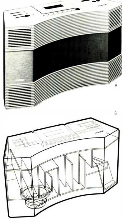
Fig. 5--Exterior (A) and cutaway view (B) of Bose’s Acoustic Wave Music System.
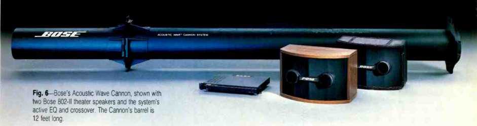
Fig. 6--Bose s Acoustic Wave Cannon, shown with two Bose 802-II theater speakers
and the system's active EQ and crossover. The Cannon's barrel is 12 feet long.
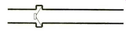
Fig. 7--The Acoustic Wave Cannon's internal construction.
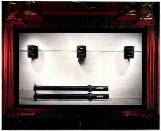
Fig. 8--Typical behind-the-screen installation of Bose’s Cinema Sound System,
showing the Acoustic Wave Cannon and three Model 802s.
The OBE Solution
The optical bass-enhancement circuit reduces the audibility of the low-frequency noise through the use of a single-ended, downward-expansion system for noise reduction. Very simply, when the bass level recovered off the film is low, the OBE circuit assumes that it is primarily noise and reduces its level further. Bass energy at moderate and high levels is allowed to pass unaltered. About 10 dB of noise reduction is possible.
Since the optical film sound system doesn't have any inherent limit to low-frequency reproduction, the use of the OBE circuit allows optical film sound systems to record and reproduce deep bass with an acceptable level of low-frequency noise.
The Use of Bass in Film
Film sound consists of three elements: Music, dialog, and effects. It's usually the effects that provide the deep bass energy. One type of deep bass effect is meant to be subtle: Low levels of continuous, deep bass energy can be used to help create a sense of fear or danger in the audience. The other deep bass effect is not so subtle: Explosions, spaceships, and similar effects can literally shake the room in a well-equipped theater.
These sorts of effects simply are not present in typical music. Except for pipe organs or synthesizers, there is rarely acoustic energy below 40 Hz in music [2]. Modern recordings having deep bass energy usually have it because of the addition Of sound effects to the music.
When we began designing the Bose Cinema Sound System, we needed to determine typical spectra present in film soundtracks. Such studies have been done several times in the past few decades for music recordings.
One study that had been done in the field of cinema sound involved measuring the peak sound pressure levels in third-octave bands in the theater as the film played. Such a study doesn't tell us all we need to know. The amplifiers and speakers in the theater were assumed to be fully capable of reproducing the peaks on the film. However, if a power amplifier clipped momentarily on a peak, or if a speaker began to reach its range of nonlinear operation during the measurement, the actual peak level on the film would not be reproduced in the theater and thus would not be measured there.
Thus, in order to determine the requirements for a cinema speaker, we had to measure the optical tracks on release prints of typical films. The Dolby cinema system has specific requirements for playback level. A given level on the film is played back at a specific sound pressure level in the theater when the Dolby Stereo processor is set up to Dolby specifications.
So, by measuring the peak level in each third-octave band on the film, we could calculate what sound pressure level would be needed to reproduce that sound in the theater. In this manner, we found the peak levels needed in each third-octave band to reproduce these films in a theater.
We examined 11 films in release at the time the experiment was performed, in the mid-1980s. The films ranged from Return of the Jedi and Ghostbusters to Gandhi and Passage to India. A third-octave real-time analyzer was used to find the peak level on 35-mm Dolby Stereo release prints in each third-octave band for the center channel and for the subwoofer OBE channel. By making additional measurements on the Dolby cinema processor and by using Dolby specifications for playback levels in the theater, we calculated the peak sound pressure level required to play these films.
The results are shown in Fig. 3. The center-channel amplifier and loudspeaker must be able to produce peaks of 96 dB SPL in each third-octave band from 40 Hz up to 1 kHz, with a gradual roll-off at either end of the spectrum. However, the subwoofer amplifier and speaker must be able to produce over 100 dB SPL in each third-octave band between 30 and 60 Hz. This is a prodigious amount of low-frequency energy.
If we were to make similar measurements on newer films, I suspect that we would find even higher peak levels.
All of the films in our original study were encoded with Dolby A-type noise reduction. As mentioned, an increasing number of current films are using Dolby SR noise reduction. According to information published by Dolby Laboratories [3], Dolby SR allows substantially higher peak levels at the extreme low end of the spectrum, as shown in Fig. 4. It's likely that this greater peak level capability is used by sound mixers and designers, and this places even greater demands on low-frequency loudspeakers.
Bass Reproducers
Knowing the enormous demands placed on bass speakers in the cinema, how do we meet those demands? In order to generate high sound pressure levels at low frequencies, it is necessary to move a lot of air. The most common approach is to use a ported enclosure. The work of Thiele and Small has made the design of such enclosures much more straightforward than it once was. Such boxes end up being large, with large speaker cones, in order to generate the needed sound pressure level.
Fig. 9 Wire-frame model of typical movie theater, produced with Bose Modeler software. Letters A, K, and B indicate the location of left, center, and right Bose 802 loudspeakers; L indicates the location of the Acoustic Wave Cannon, and C through J show locations of the surround-channel Bose Model 102 speakers.
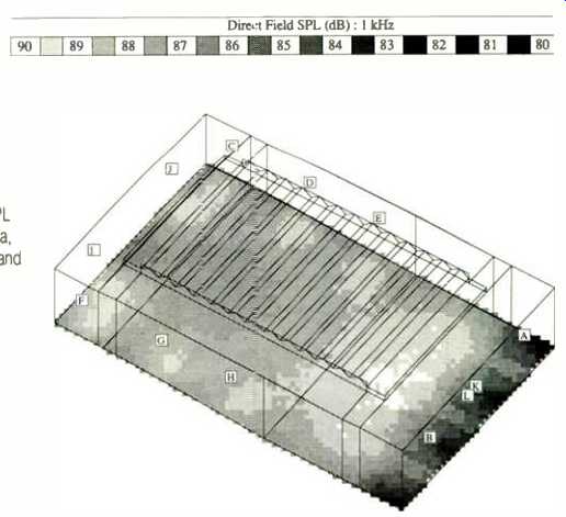
Fig. 10--Prediction by Modeler software of SPL in theater's seating area,
for the 1-kHz octave band with 1 watt fed to each loudspeaker.
Fig. 11--A single-sided Bose Acoustic Waveguide system's internal construction.
Fig. 12-Typical velocity standing-wave envelope.
Fig. 13--Velocity standing-wave envelope for the frequency at which the waveguide’s length is slightly less than 1/4 wavelength.
Fig. 14--Same as Fig. 13 but waveguide is slightly less than 3/4 wavelength.
Another approach is to use horn-loaded loudspeakers. Horns can have high efficiency, which is one reason why they have traditionally been used in cinemas. However, a simple calculation shows that, in order to reproduce down to 25 Hz, the mouth of the horn must cover 150 square feet; this results in an impractically large structure.
At Bose, we chose to use our Acoustic Waveguide technology to make a bass speaker for cinema applications.
This technology allows us to make an efficient bass loudspeaker in a small volume, allowing for a wide variety of installations. The Acoustic Waveguide principle was invented by Amar Bose and me in the early 1980s. Because of my frustration with existing subwoofers while installing Dolby cinema processors in the late 1970s, one of the first Acoustic Waveguide speaker prototypes I built was a subwoofer for cinema applications.
The first commercial product to use the Acoustic Waveguide technology was the Bose Acoustic Wave Music System, introduced in 1984. This unit, shown in Fig. 5, is an all-in-one system consisting of an AM/FM tuner, a cassette deck, amplifiers, and speakers using the Acoustic Waveguide principle. The waveguide is folded, allowing its nearly 7-foot length to fit within the cabinet. Despite the system's small size, Acoustic Waveguide technology allows it to have solid, efficient bass performance down to 50 Hz.
The Acoustic Waveguide technology was applied to cinema with the introduction of the Acoustic Wave Cannon, designed by Ken Jacob at Bose, in 1987 (Fig. 6). It consists of a single 12-inch woofer captured between two Acoustic Waveguides totaling 150 inches in length (Fig. 7). Hardware built into the waveguide allows multiple units to be stacked in large installations, and allows the stack to be suspended or wall-mounted if needed.
The complete Bose Cinema System consists of Acoustic Wave Cannons for bass reproduction, Bose 802 speakers behind the screen for the mid and high frequencies, and Bose 102 speakers for the surround channel. A typical behind-screen installation is shown in Fig. 8. An active equalizer and crossover are used. Bose Modeler design software allows designers to predict accurately the audience coverage of the system, the placement and required number of speakers, and the required amplifier power. The designer begins by creating in the computer a "wire-frame" model of the theater, as shown in Fig. 9, and specifying dimensions and materials. Using the model, speakers are placed and aimed, and the resulting sound field is predicted (Fig. 10).
Acoustic Wave Technology
How is it possible to create the high sound pressure levels at bass frequencies that films demand, using a speaker as small as the Cannon? The answer lies in Acoustic Wave technology. It permits a relatively small loudspeaker to produce large amounts of low-frequency energy.
The Acoustic Waveguide matches the motion of the loudspeaker cone with the motion of the air more efficiently than can be done by the speaker alone. Its operation is not unlike a lever. If you need to move a stone too heavy for you to lift unaided, you might use a lever to move it. The lever matches your available force and range of motion to a force and motion more suitable for moving the stone. Similarly, a loudspeaker cone is not ideally suited for moving air. Typical loudspeaker technologies have efficiencies of under 1%. An Acoustic Waveguide allows for a sensitivity improvement of 6 dB or more.
Acoustic matching devices are not uncommon. A flute or an organ pipe is a matching device. A relatively small breath of air at one end of a flute can create a note loud enough to fill a concert hall. This is possible due to the matching action of the flute. However, a flute or organ pipe matches only one frequency (and its harmonics) at a time. In order to apply this principle to a loudspeaker, we need to be able to make the matching occur over a wide range of frequencies simultaneously.
We can achieve this goal with Acoustic Wave technology, but the details are complex. However, it is possible to get a sense of how Acoustic Wave technology works without having to use a lot of mathematics, by using some explanations and diagrams.
First, we'll look at a one-sided Acoustic Waveguide (Fig. 11) before looking at the two-sided Acoustic Waveguide that is used in the Acoustic Wave Cannon. In a one-sided Acoustic Wave-guide, one side of the loudspeaker diaphragm is coupled to the waveguide, while the other side radiates into the listening area.
The Acoustic Waveguide can be modeled as an acoustic transmission line. In the case of an Acoustic Wave-guide speaker, one end of the transmission line is coupled to the speaker, which we will crudely model as a velocity source at first, and the other end is open to the air. The velocity source launches velocity waves into the wave-guide.
Because the acoustical impedance of the waveguide's open end is a poor match for that of the room, velocity waves launched by the speaker in the waveguide are reflected at the open end, setting up standing waves inside the waveguide. Putting it simply, the boundary conditions are that the air-particle velocity at the speaker end of the waveguide must match the velocity of the speaker diaphragm and that the incremental air pressure at the open end of the waveguide must equal zero.
The latter condition means that there is no sudden change in air pressure from just inside the open end of the wave-guide to just outside it.
At a given point along the wave-guide, the air velocity varies sinusoidally in time, with a frequency equal to the driving frequency of the source and with a particular magnitude. The magnitude depends on the boundary conditions and on the length of the tube relative to the wavelength of sound for the source frequency. If the magnitude is plotted along the length of the waveguide, we can see the envelope of the velocity standing wave.
Figure 12 shows one possible standing wave envelope. Distance along the waveguide is plotted horizontally, with the source located at 0 and the open end at L. The velocity magnitude is plotted vertically; the velocity of the source is indicated by Vs.
Note that a fundamental difference exists between Acoustic Wave technology and the more familiar transmission line or labyrinth speaker systems.
Typical transmission line speakers use absorptive material or other acoustic resistances to damp out standing waves. In such systems, standing waves are undesirable, and so designers of such systems try to prevent their formation. In Acoustic Wave speakers, though, the standing waves are an essential part of the system's operation.
As we will see, the standing waves permit the sensitivity increase that is one of the major benefits of the Acoustic Wave technology. Thus, in designing an Acoustic Wave system, we do everything possible to maximize the generation of standing waves.
If we solve the wave equation in the waveguide for a range of frequencies, we find there are several key frequencies. At frequencies where the length of the waveguide is an odd multiple of one-quarter wavelength (such as 1/4, 3/4, 5/4, etc.), the air velocity at the open end of the waveguide is very much larger than that of the source. This condition is shown in Figs. 13 and 14.
Virtually all of the acoustical energy is radiated from the open end. Since the air velocity at the open end is greater than the velocity of the speaker cone, the energy radiated by the waveguide system is very much greater than the speaker could produce alone.
===========
Bose Cinema Sound Installations
UNITED STATES
Arkansas
Fayetteville: Malco Twin Jonesboio: Malco's Cinema 10 Little Rock: UA Park Plaza 7
Illinois
Champaign: Country Fair Cinema
Ohio
Alliance: Carnation Mall Cinema Bowling Green: Woodland Cinema
Chillicothe: The Movies at Shawnee Square Piqua: Miami Valley Cinema
Michigan
Bay City: Westtown Theater
Oregon Portland: Moyer Theaters Tennessee Union City: Hollywood Theaters
Virginia Christiansburg: RC Theaters/New River Valley Mall
OVERSEAS
Australia
Brisbane: Hawthorne Twin Cinemas
Sydney: Bondi Junction Mall
China
Jia Shátcity: Jia Shan Movie Theatre
Germany
Buckeburg: Residenz-Kino Wuppertal: City-Kino
Japan
Tokyo: Cine Saison
South Korea Seoul: Seoul Cinema Town
Switzerland
Lausanne: Open Air Cinema Lugano: Open Air Cinema
Zurich: Open Air Cinema
===========
At frequencies where the length of the waveguide is an even multiple of one-quarter wavelength (such as 1/2, 1, 3/2, 2, etc.), the air velocity at the open end of the waveguide is the same as that of the source. For some of these frequencies, where the waveguide is an odd multiple of one-half wavelength (1/2, 3/2, etc.), the air velocity at the open end of the waveguide is the same as the source's but with the opposite polarity. This case is shown in Fig. 15. Since the source for the wave-guide is the rear of the speaker cone, which has the opposite polarity from the front of the cone, the front of the cone and the open end of the wave-guide have the same air velocity and polarity. They add in phase, resulting in a doubling, or 6-dB increase, in acoustic output compared to the same speaker in an infinite baffle.
Problems occur when the wave-guide length is a multiple of 1 wavelength, shown in Fig. 16. Here, the air velocities at the front of the speaker and at the open end of the waveguide are the same but with opposite polarities. The system acts like an acoustic dipole and has little acoustic output.
So the waveguide provides both a velocity gain and a polarity reversal that is periodic with frequency. The general form of the velocity gain (for the ideal lossless case) is represented in Fig. 17. As a result of this velocity gain, the Acoustic Wave system provides much more acoustic output than the same speaker in an infinite baffle.
This improvement in speaker sensitivity for a single-sided Acoustic Wave-guide is sketched in Fig. 18. For a range of frequencies slightly greater than three to one, the Acoustic Wave-guide system provides substantially greater speaker sensitivity.
Fig. 15-Same as Fig. 13 but waveguide is slightly less than y wavelength.
Fig. 16-Same as Fig. 13 but waveguide is slightly less than 1 wavelength.
Fig. 17-Waveguide velocity gain as a function of wavelength relative to the waveguide length.
The presence of the notch, at the frequency where the waveguide length equals 1 wavelength, might prevent using the system over a broad frequency range, even though the speaker's sensitivity improves again at some frequencies above the notch. However, we can control the depth of the notch through adjustment of some waveguide parameters, allowing us to build full-bandwidth Acoustic Wave systems, such as the system used in the Ensoniq Acoustic Wave Piano with Sound by Bose.
Another approach is to move the notch to a frequency outside the band where the speaker will be used. We can achieve this goal by placing an additional waveguide to the front of the speaker, as is done in the Acoustic Wave Cannon. This second waveguide reverses the polarity of the velocity contributed by the front of the speaker diaphragm at the appropriate frequency. Since this front waveguide will also provide velocity gain, its addition to the system not only extends the bandwidth but also further improves the system sensitivity.
The front waveguide must be one-third the length of the rear waveguide.
Under this condition, the velocity gains of the two waveguides are as shown in Fig. 19. At the frequency where the rear waveguide is three-quarters of a wavelength, both waveguides provide considerable gain, and both change their polarities. Thus, the outputs of both waveguides continue to add in phase until the rear waveguide changes polarity at the frequency at which it is five quarter wavelengths long.
As a result, the addition of the front waveguide increases the bandwidth of the Acoustic Waveguide system to a frequency range of greater than five to one. The null which results when both waveguides have the same velocity magnitude but opposite polarity now occurs at the frequency where the rear waveguide length is three half wavelengths. A sketch of the sensitivity improvement for a double-sided Acoustic Waveguide loudspeaker is shown in Fig. 20. In practice, the operation of an Acoustic Waveguide system is complicated by the fact that the waveguides significantly load the speaker diaphragm. Thus, the loudspeaker is not the stiff velocity source assumed above. The velocity of the speaker cone at the frequencies where the waveguides have significant gain is considerably smaller when loaded by the waveguide than when loaded in an infinite baffle. In addition, the gain of the waveguide is not as great as expected due to the fact that the wave-guide has some loss, and because the waveguide is not truly open at one end but, rather, has some air load. Thus, the response of the Acoustic Wave-guide speaker cannot be inferred easily from the figures shown.
A more accurate model requires the blending of two different modeling techniques. The first, in which the wave nature of sound is put aside, is called lumped parameter modeling and is commonly used for speaker analysis.
In such a model, the loudspeaker and enclosure are represented by acoustical and mechanical springs, masses, and resistances. However, such a model is impractical for modeling devices in which wave phenomena play an important role. The second technique is wave analysis. Wave analysis requires solution of the full wave equation, which is the physical basis for our understanding of acoustics.
In order to model an Acoustic Wave speaker system, we first generate a lumped parameter model of the speaker and couple this model to the solution of the wave equation inside the Acoustic Waveguide. Rather than obtaining one equation, we get several equations that must be solved simultaneously. There is no closed-form solution, as there is with conventional loudspeaker enclosures, that would allow us to predict speaker performance quickly.
Fig. 18--Improvement in loudspeaker sensitivity for a sing e-sided Acoustic
Waveguide system, shown as a function of wavelength relative to the waveguide
length.
Fig. 19--Waveguide velocity gain as a function of frequency for the long waveguide (dotted curve) and the short waveguide (solid curve) in a double-sided Acoustic Waveguide system. Frequency is shown as a function of wavelength relative to the longer waveguide's length.
Fig. 20--Improvement in loudspeaker sensitivity for a double-sided Acoustic Waveguide system, shown as a function of wavelength relative to the longer waveguide's length.
From the equations, we see that there are about a dozen key parameters in an Acoustic Wave system. The electrical and mechanical properties of the speaker, and the physical properties of the waveguide, must be harmoniously selected to create a system with a smooth response while maintaining high efficiency.
Normally, simply placing a loudspeaker at the end of a tube results in resonances, giving a peaky characteristic to the reproduced sound. An appropriate combination of loudspeaker electrical, magnetic, and mechanical properties damps the resonances to the point of inaudibility while maintaining a high system efficiency.
Because of the complexity and interlocking nature of the equations, and because of the large number of key parameters, design of Acoustic Wave-guide speakers relies heavily on computer design aids, which can solve the equations and predict a frequency response in a matter of seconds. These aids allow us to design systems to meet the particular needs of specific applications.
Once the acoustic design is completed, careful mechanical design is required to minimize air turbulence in the high-velocity sections of the wave-guide and to minimize wall flexing in the high-pressure sections. Correctly constructed units have acoustical performance that matches the computer model to within a fraction of a decibel.
Future Trends
Through the use of Acoustic Wave technology, it is possible to meet the requirements for bass performance for current films. However, some exciting developments are on the horizon. Eastman Kodak and Optical Radiation have announced a joint program to put a digital stereo optical soundtrack on motion picture film. The Cinema Digital Sound (CDS) system records five full-bandwidth channels plus a bass channel in the normal soundtrack area on motion picture film using 16-bit samples at 44,100 samples per second [4]. This is an extraordinary achievement, since the required bit size is extremely small. Also, since film has no protective layer over its image surface as a Compact Disc does, the error-correction algorithms of digital cinema sound have to be very robust.
The performance of the five channels is comparable to that of Compact Discs. Frequency response is 20 Hz to 20 kHz, "0.5 dB, with low distortion, extremely low noise (S/N greater than 90 dB), unmeasurable wow and flutter, and minimal crosstalk between channels (channel separation greater than 90 dB). Three of the five channels are placed at the left, in the center, and right behind the screen; the two remaining channels are used for left surround and right surround. The separate bass channel allows prodigious bass effects without diminishing the dynamic range of the other five channels. Further, a digital control channel is used for control signals, including a MIDI track and SMPTE time code, and can be used for purposes such as projection-booth automation, special effects in the theater, and quality-control assurance of the release print and of the theater projection and sound equipment. Originally available only on 70-mm film, the Cinema Digital Sound system is now available on the more commonly used 35-mm film, with exactly the same specifications and performance. To date, six films have been released with CDS soundtracks, and more than 40 theaters have installed CDS playback equipment.
In June 1991, Dolby Laboratories gave a public demonstration of their competing digital optical film sound system, Dolby Stereo SR-D. It has similar performance specifications to the CDS system's. However, the Dolby system keeps the normal analog optical soundtrack in its standard position, and adds the digital information between the sprocket holes along one edge of the film. Digital data compression is used in order to fit all of the audio data into the limited space. The first SRD release is expected in early 1992, with widespread availability late in 1992.
For the first time in decades, cinemas will routinely be able to play source material having performance equal or better to that of the very best home stereo systems. Like the change that occurred in the recording industry when Compact Discs were introduced, a digital film sound system will require changes in the way film soundtracks are recorded and mixed. Sloppy practices that currently are hidden in the noise of an analog soundtrack will be painfully obvious to audiences listening to a digital cinema system. The introduction of digital systems will place even greater demands on cinema loudspeakers all across the audio band, and especially in the low-frequency end of the spectrum. We believe that the Bose Cinema Sound System is ready for the demands of digital soundtracks. For over a year, a Bose Cinema Sound System has been used in the Optical Radiation laboratory where the CDS digital film system has been developed. The two digital systems are certain to make a major improvement in the sound quality obtainable from motion pictures.
Conclusions
Recent films have been shown to contain signals requiring very high sound pressure levels in the bottom octave of the audio band. Current films using Dolby SR noise reduction potentially have even greater demands.
And, shortly, there will be digitally encoded film soundtracks capable of enormous dynamic range at frequencies as low as 20 Hz.
The Acoustic Wave technology, as used in the Bose Cinema Sound System, allows accurate reproduction of this bass energy in a small, efficient package. It can meet the demands of soundtracks now, and in the future as the art and science of film soundtracks continue to improve.
References
1. Nairn, Charles and Bruce Hofer, "Extended Range Cross-Modulation Testing," 131st SMPTE Technical Conference, October 1989.
2. Fielder, Louis and Eric Benjamin, "Subwoofer Performance for Accurate Reproduction of Music," Journal of the Audio Engineering Society, Vol. 36, No. 6 (June 1988).
3. Allen, loan, "Technical Requirements of Theaters Playing Back Dolby Spectral Recording Photographic Sound Tracks," 131st SMPTE Technical Conference, October 1989.
4. Flemming, Howard and Ronald Uhlig, "Cinema Digital Sound-The Technology," 132nd SMPTE Technical Conference, October 1990.
(source: Audio magazine, Nov. 1991)
Also see:
What Ever Became of Frequency Response? (Jun. 1991)
FORTÉ AUDIO MODEL 4 POWER AMP (Nov. 1991)
= = = =