by Martin Clifford
EVERY ELECTRONIC SIGNAL from whatever source ultimately appears at the signal input of the main or power amplifier. The FM signal has shucked off the cocoon supplied by the radio-frequency carrier wave; the phono signal becomes the electronic equivalent of the twists and gyrations of the stylus in the record grooves; the tape signal has emerged from the magnetic whirls that produced it. Thus, at the input to the main amplifier, all of these signals resemble each other closely, and you can select any one of them for processing by the main amp.
Up to this point, we have been interested only in the voltage amplitude of the signal, and we've talked in terms of signal voltage, not signal current or power. It is true that the main amp will provide some further voltage amplification, but that is incidental to its main job. What we need is electrical power for our speakers. In this sense, we may regard the amp as an appliance-a device for turning electrical power into some other kind of energy-just as a toaster, broiler, or a steam iron is an appliance which converts electrical energy into heat.
Although the terms "power amp" and "main amp" are often used interchangeably, "power amp" unfortunately suggests that it somehow manages to amplify power; this is wrong. This amplifier takes electrical energy out of the household electrical outlet and delivers it to one's loudspeakers. However, it doesn't do this directly--changes must first be made in the frequency and amplitude of the electrical power. These changes will be dictated by the audio signal input to the main amp.
Whence the Power
While the signal at the input to the power amp is a complex a.c. waveform, it is just a voltage and can exist at the amp's input without any sound coming out of the speakers.
This is comparable to the case in your home in which an a.c. voltage is present at every power outlet along the baseboard, yet whether power is used or not is your decision.
The moment you decide to use it (by plugging in an appliance), we are no longer dealing just with voltage (which is pressure), but with voltage and current (electrons flowing). Taken together, these two constitute power.
The power amp does not generate power-it is simply a device for controlling the power made available to it by its power supply (usually on the same chassis). (See Fig. 1.) And that power supply gets its power from your a.c. power line outlet. This may seem like a Rube Goldberg way of doing things, but it's the only way we have. The ideal method would be to eliminate the amplifier by connecting the signal voltage to the a.c. power line, and connect the result to the speakers. Instead we must take from the a.c. line the a.c. power, which consists of a sine wave voltage and a sine wave current, and convert it to d.c. This is the function of the amplifier's power supply.
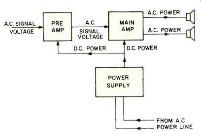
Fig. 1--The power delivered to the speakers by the power amplifier comes
from the power supply, but is controlled by the signal voltage.
The power amp, then, is a component which receives d.c. power from its power supply section and reconverts it to a.c., which varies in frequency and amplitude according to the input signal (program material). The power line supplies current which is a sine wave, usually 60 Hz in frequency. The audio power coming out of the amplifier varies from about 30 to 20,000 Hz (depending on the amp design), and its amplitude is continuously changing. This current, flowing through the voice coil of the speaker, accomplishes work. It's forced into the voice coil by voltage. Together the two may be measured to compute the amount of power the speaker uses.
Function of the Audio Signal
One way to describe the relationship between the audio input signal voltage and the amplifier is to say that the amp is a faucet and the input signal voltage is the valve in that faucet. While the amplifier directs the current to its appointed location, the input signal controls how much of that signal will reach the locations. The current flowing through the speaker voice coil should also have the same waveshape as the controlling signal. If it's exactly the same (it can never be a perfect copy-that would mean zero distortion!), the amp has done its job perfectly. If it changes very little, it's done a good job. If the output power has things in it that weren't in the input signal, or if it changes their relative amplitude, we have distortion.
Power Amp and Power Supply
Since the power amp gets its power from the power supply, it should be obvious that it cannot deliver more power than it receives from the house current a.c. line. The function of the power supply is quite simple-to rectify the power line a.c. current and deliver d.c. to the power amp. It may help if you consider the power supply as a d.c. power reservoir. The power supply consists of three important parts: a transformer, a rectifier, and the filters. The transformer changes the house current at 115 volts to whatever the amp requires (in tube days it was 300 to 500 volts; generally today it's between 30 and 80 volts). In addition the transformer isolates the amplifier from the power line. If it did not, we'd have the good possibility of lethal shock, which is present in most small TV sets and many other appliances connected directly to the power line (they all have insulated cabinets to protect the user). The rectifier converts the a.c. into pulsating d.c. And the filters, consisting mostly of large capacitors, smoothes the pulsating d.c. supplied by the rectifier into nearly perfectly smooth d.c. In the days of tube equipment, power-supply capacitors ranged up to 500 microfarads (NF). But today, with much lower working voltages, the size of many capacitors is in the 10,000 if range and up.
Describing Power
Measuring d.c. power is easy. Nor is it all that difficult to measure sinewave a.c. power. But it becomes troublesome when we are talking about complex wave signal currents and signal voltages-that is, signal power. For d.c., we just multiply voltage and current to get power in watts. For example, two amperes of current at 30 volts equals 60 watts power. Simple. For sine wave a.c. (if the voltage and current are in phase), the same simple multiplication process is used: Voltage (E) times current (I) equals watts power (W). The formula is written IxE= W. However, because we use a.c. power in many ways, we make several different measurements of a.c. waves, as may be seen in Fig. 2.
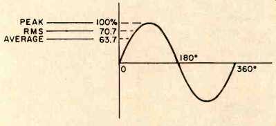
Fig. 2-Peak, rms, and average amplitude points on a sine wave of voltage
or current.
There are three main points at which a sine wave is usually measured. One is at the top, called the peak (though it could as well be the bottom). Another is the rms value, which is equal to 70.7% of the peak value. This is also called the effective value. Finally we come to the average, which is equal to 60.3% of the peak value. Note that the sine wave values we're discussing here may be either voltage or current but not power.
Remember that except for test purposes, the wave shapes a speaker receives are very rarely simple sine waves. Instead they're complex shapes produced by voices and instruments. Further, the speaker doesn't use just need voltage, or just current, but both, which is power. Now, while many measuring instruments are calibrated in rms units (voltmeters and ammeters), a wattmeter measures average watts.
That's because the product of rms volts and rms amperes (voltage and current) is not rms watts, as you might imagine, but average watts. Thus, when you read a spec sheet saying so many watts rms, think average watts instead. While rms watts is thus a misnomer, you might also hear rms power sometimes also called continuous power because this is the amount of power the amp can handle for an indefinite period of time without interruption.
Power amps are able to deliver more than their average (so-called rms) power for short periods of time, depending on the demands of the program material. If there is a pianissimo passage followed by a sudden clash of cymbals, the demand for additional power is comparable to momentarily turning on the air conditioner in your room-either the power company delivers or you will remain just as warm as you were. Ditto with the power amp. It will deliver more than the average power, but how much more depends on the size of the filter capacitor reservoir and the current passing ability of the rectifiers (and the transformer) in the power supply. This emergency power is variously called maximum power, dynamic output, or music power. Music power is the maximum power available for a very short period from the main amp and used to be seen fairly widely on spec sheets and in catalogs until late 1974 when the Federal Trade Commission (FTC) power-rating rule went into effect.
Music power described the amp's ability to handle brief power peaks as compared to sustained power levels. Thus, an amplifier capable of delivering 50 watts of power continuously might also be capable of delivering 80 watts for a short period of time. It was this 80 watts which would have been the amp's music power rating. With the FTC amplifier power-rating rule in effect now, only one kind of power rating, continuous, will be used for good high fidelity equipment. All other ratings are now obsolete.
Power Output vs. Frequency
Ideally, for a fixed amplitude input signal, a power amp should be able to deliver the same amount of output power over a wide frequency range, extending from sub-audible to super-audible, say 20 Hz to 20,000 Hz. Maximum available power output can vary within these limits, sometimes dropping off substantially at the ends of the spectrum or having various peaks in between. At the ends, the power may even decrease by 50 percent or more. In fact, the frequencies at which available power is 3-dB down (which happens to be 50 percent) at each end of the audio spectrum were called the half-power points, and they were used to define the useful power bandwidth of an amplifier previous to the FTC ruling. Under the new ruling, however, the full power of the amplifier must be available at all frequencies mentioned, with no decrease allowed at the ends of the frequency spectrum.
Power Handling Capability
Speakers, as well as power amps, may be treated in terms of their power-handling capabilities, just as electric light bulbs are marked 10, 60, or 75 watts. We cannot draw further parallels between speakers, amps, and light bulbs, however, because the marking on a light bulb ¡Weans that it always dissipates just that number of watts, not less, not more (provided it's being fed the nominal 115 V a.c.). However, if a speaker is rated at, say, 60 watts, that means it can handle power up to (but not exceeding) that level. It doesn't demand (as does the light bulb) that much power when it's hooked up to the amplifier. If we try to run more power through the speaker (by feeding it signals of higher voltage pressure), thus resulting in too much power being dissipated in its voice coil, one of three undesirable things is likely to transpire. Either the voice coil will move too far out of its magnetic gap and stick, never to return, the voice coil may just burn out, or the speaker will just make horribly distorted sounds.
Impedance Matching
A high quality power amp will deliver its rated power provided the load (the speaker) is designed to accept this amount of power. One of the problems here is that the impedance of the speaker is not a fixed value. It varies from its nominal value all over the lot, changing as it goes up and down the audio spectrum; at 70, 80, or 100 Hz the impedance may be five times higher than nominal, and it may also measure 40 ohms or more at the high end of the frequency range. This may sound discouraging, and it is, because the result of the peak is a droop in power transfer. If the peak occurs at the low frequency end, there is a reduction in the transfer of power from the amplifier by the speaker, just where we need extra power for those deep bass notes. There is an even bigger problem with impedance dips which, if deep enough, will give the amplifier fits.
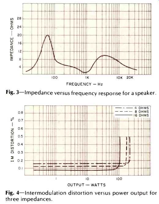
Fig. 3--Impedance versus frequency response for a speaker.
Fig. 4--Intermodulation distortion versus power output for three impedances.
Figure 3 is an impedance curve for a hypothetical loudspeaker. At about 100 Hertz this unit does indeed have an impedance of 8 ohms. However, the curve shows that the impedance of this speaker wanders all over the place, with a peak somewhere around 60 Hertz. This peak decreases the amount of current delivered to the speaker at that frequency, resulting in lowered acoustic output. Fortunately, the peak in the curve at that point is due to speaker resonance.
Now, a speaker is more efficient around its resonant frequency than anywhere else on its curve. Thus, even though less current is delivered to the unit at resonance, the bass loss there isn't as severe as it might otherwise be, due to its increased mechanical efficiency at that point.
Note also the severe dip in the mid-range region around 1 kHz. The low impedance at that frequency can put excessive current drain on the amplifier, possibly causing the amp's protective relay or fuse to open. Whether this happens or not will depend on the setting of the preamp's gain control as well as the signal level fed into the preamp.
Damping Factor
Many speaker terminals are labeled 4-8 ohms so you might think that this represents the impedance of the amplifier. Not so at all! This is simply a direction to the installer, "Attach the two speaker wires here." There is actually a tremendous mismatch, since the internal impedance of the amp may be measured in tenths of an ohm. The ratio of the impedance of the amplifier to the speaker's voice coil impedance is called the damping factor, which describes the amp's ability to control or minimize unwanted, residual speaker movements such as hangover and ringing. If a speaker has an impedance of 4 ohms and the amplifier has an internal impedance of 0.04 ohms, the damping factor would be 100.
Total Harmonic Distortion (THD)
The amplifier must not only deliver power to the speakers, but should do so with the least possible distortion. To indicate that an amp has a certain amount of THD at a particular frequency is analogous to saying that an auto gets 18 miles per gallon when moving along at 10 MPH. But what about 40 MPH, or more relevantly, 60 MPH? An amp that is listed as having less than 1 percent THD at 1 kHz could easily have several percentage points of THD elsewhere in the sound spectrum. With amps it is best to know the maximum THD over the entire frequency range at maximum power.
Then you can be certain that at most frequencies and power levels there will be less distortion than maximum-a reassuring feeling.
Distortion is also related to the power output in watts (Fig. 4). Maximum distortion appears at the maximum power output of the amplifier, where waveform clipping begins to take place as the distortion rises sharply. Figure 5 shows percentages of total harmonic distortion for 4and 8-ohm arrangements working single channel and dual channel.
THD is a main limiting factor in power amp ratings. If there were no specified THD, then power output would become a "numbers game" and have no real meaning. The power specification of amplifiers, then, must list, in addition to THD, the sine wave continuous or average power output, in watts per channel, for each load impedance, with all channels driven, and with the power bandwidth in Hertz.
Frequency Response
At one time the frequency response of an amp was a sacred cow, and for good reason. The amp, in those olden days, was about as guilty as the phono cartridge (or other signal source) or the speaker in contributing to degradation of sound. But not any more, so far as amps are concerned, since the frequency response of a quality amplifier can range from a low of 7 Hertz or so to a high of 80 or more kHz with a variation of +0,-1 dB, usually measured at a 1-watt level. Now that is a mighty flat response. When plotted on a graph, it looks as though it was drawn with a straightedge.
But before you clap your hands with joy, consider that the load (the speaker) has a response curve quite different-more like a mountain range.
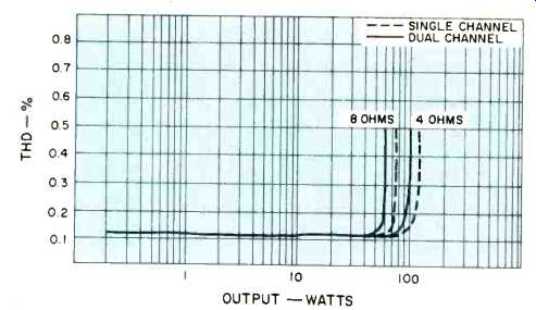
Fig. 5--Total harmonic distortion versus power output for two impedances,
showing effect of single versus dual channel operation on power output.
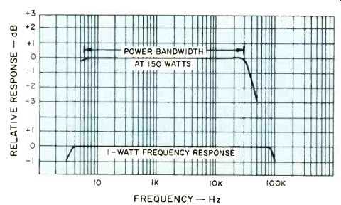
Fig. 6--One-watt frequency response and bandwidth at full power for a 150-watt
amplifier.
And if you are going to use low and high filters and tone controls before the signal reaches the main amp, getting terribly perturbed about a 1-dB variation in an amp's frequency response is fretting unnecessarily. This doesn't mean you shouldn't pay attention to frequency response. You should, for having an amp with a flat frequency response eliminates an undesired variable from at least one component. But it does not mean you are automatically guaranteed an equally automatically faithful sound output. High fidelity is more than a goal; it is a proper perspective. (See Fig. 6).
Two-Channel Amplifiers
Stereo amps are two-channel devices, that is, two amplifiers built on one chassis, with the power supply for both also on that chassis. In the past specification sheets often indicated the total wattage of both channels when specifying power output. Usually, too, there is less power available when both channels are driven simultaneously, than if one channel is operated alone. The new FTC power statement ruling requires that they be stated per channel and with both channels driven at once.
Amplifier Protection Circuits
At one time speakers were isolated from the output stages of the main amp by transformers. These devices transferred the audio current to speaker voice coil while they blocked d.c. current (coming from the power supply). The main amp needs d.c. for its transistor elements and gets this from the power supply. What the speaker voice coil requires, however, is an alternating current whose waveform resembles that of the voltage signal input to the main amp. But while transformers perform the separation function admirably, they are frequency-sensitive devices and so pass some frequencies on easily to the loudspeaker while impeding others.
A direct-coupled stage, now used in most modern amps, is one in which the output stage is directly coupled to the speakers. A problem arising from this practice is that failure of an output transistor may produce a heavy flow of current though the speaker's voice coil, damaging or destroying it.
Another possible cause of trouble can be damage to the transistor amplifier output stage caused by a short circuit across the speaker leads.
To prevent these problems, amps now have a variety of protection circuits which shut down the power amp at the first sign of trouble. These can be simple thermal fuses or complex circuits which detect any severe drop in output load impedance, especially a short circuit. Some power amplifiers use protective relays which can open the connection between the amp and the speakers, a somewhat more expensive arrangement than a simple fuse. Silicon controlled rectifiers (SCRs), which are faster and thus protect more quickly, are also used to protect the output stage. Still other and even more sophisticated circuits sense the levels of voltage and/or amperage and can shut down the amplifier very quickly should an excessive level of either occur.
Yet another form of protection exists in the speaker relay found in most amplifiers and receivers nowadays. You've probably noticed the few second delay between the time the unit is turned on and when sound begins to be produced by the speakers; this is the action of the relay, which prevents transient current peaks which occur at turn-on from reaching and possibly damaging the speakers.
Speakers and power amplifiers are hi-fi's electronically married couple. They not only work together closely, but the actions of one affects the other. It is this relationship we will explore in the next installment.
--------------------
From Microvolts to Femtovolts
By Len Feldman
AS MANY of our readers may already know, new standards for measurement of FM tuners and receivers were recently approved by the three major electronic organizations in this country, The Institute of High Fidelity, The Electronic Industry Association, and the Institute of Electrical and Electronic Engineers. Many new measurements of FM products are now called for in the new standard, including a host of previously omitted performance specifications having to do with stereo FM performance.(We will publish a definitive article on the new standards in the near future; meanwhile, those interested in the new standard can obtain a copy by sending $6.00 to the Institute of High Fidelity, 489 Fifth Avenue, New York, N.Y. 10017 and requesting a copy of Standard IHF-T-200, 1975.) One important change in terminology needs a bit of explaining right now, since our test reports dealing with FM products already reflect the use of this term-the dBf. dBf stands for "dB referred to 1 Femtowatt" and, for the uninitiated, a Femtowatt is 1 x 10^-15 watts-a very small power figure indeed. The new standards require that signal strengths, formerly given in microvolts, now be given in terms of power-or actually in dB referred to 1 Femtowatt.
The purpose of this change is to avoid certain ambiguities which were possible so long as the "microvolt" was used. It is the power of an incoming radio signal that really counts, and power involves a voltage developed across a known impedance. Clearly, 2 microvolts across 75 ohms represents exactly twice as much power as 2 microvolts across a 300-ohm impedance (P = Ez/Z). A manufacturer who chooses to measure his microvolts by feeding them into the 75-ohm antenna terminals of his FM product will therefore come up looking twice as good (or having half as much signal requirement) as a competitor in terms of such specifications as usable sensitivity (IHF sensitivity), 50-dB quieting signal, stereo threshold signal strength, etc.
By converting to statements of power rather than voltage, such ambiguities are eliminated, since power is power no matter what the impedance involved. The new dBf system will take some getting used to, and in fact, in our test reports of FM product performance we plan to give both µV numbers as the reference, and the resulting dBf numbers that correspond when the most popularly used 300-ohm antenna terminals are used.
To determine the dBf value for microvolt readings not listed (assuming a 300-ohm impedance and the old IHF "terminated" microvolts), the following formula should prove useful:
dBf = 20 log 10 uV/0.55,
in which µV equals the number of "terminated microvolts" you wish to translate to dBf.
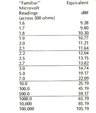
Table 1: MicroVolts versus dB re 1 Femtowatt.
--------------------
(Audio magazine, Dec. 1975)
Also see:
Harmonic Distortion by Richard C. Heyser (Feb. 1976)
= = = =