Manufacturer's Specifications:
Power Output: 60 watts per channel, continuous, 8 ohms (120 watts, 4 ohms), 20 Hz to 20 kHz.
Rated THD: Less than 0.25%, 20 Hz to 20 kHz at 8 ohms; less than 1%, 20 Hz to 20 kHz at 4 ohms.
IM Distortion: Less than 0.25%, from 0.25 to 70 watts at 8 ohms.
Damping Factor: 150 from 20 Hz to 1 kHz.
Rise Time: 3µS at 8 ohms and at rated output.
Hum and Noise: 100 dB (wide band) below rated output.
Input Sensitivity: 1.0 volt rms for 70 watts output, 8 ohms.
Dimensions: 19 in. (48 cm) W x 81/2 in. (22 cm) H x 7 in. (18 cm) D.
Weight: 35 lbs. (16 kg).
Price: $779.00.
Company Address: All-American Audio, 31316 Via Colinas, Westlake Village, Cal. 91362.
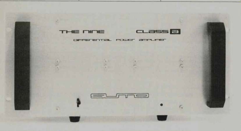
The Sumo Model Nine stereo amplifier is an interesting attempt at producing a Class-A amplifier, not least because of its suggested retail list price of $779, which is far less than the $3,000 the firm puts on the previous Class-A model, The Gold. The circuitry achieves some cost effectiveness by utilizing only two active stages. James Bongiorno, a designer credited with the classic Dynaco 400 and GAS Ampzilla amplifiers, engineered the Nine's circuitry and holds a patent on its special method of Class-A operation.
Physically, the Nine's sixteenth-inch anodized aluminum chassis is bent into two touching U-shaped sections which form the top, bottom, front and back of the unit. Eight-inch high heat-sinks are joined to both sections, forming the sides. The U-shaped top, which holds the single-speed fan, is attached to the heat-sinks, front plate, and bottom chassis by 20 bolts. Opening this amplifier involves removing the top section, not an easy or quick task. Since there are no user adjustments inside, this should not be considered a problem. The four internal 5-amp fast-blow power-supply fuses serve as last-ditch protection from abuse and prevent accidental electrical fires should a user insert an oversized line fuse. A rack-width, 8 3/4-inch-high x 5-mm-thick front panel is bolted onto the front of the chassis with 12 hex socket bolts. With an additional front-to-back brace inside and the large handles on the front, the assembly is quite rugged.
The internal layout is clean and symmetrical, but the point-to-point wiring is not particularly neat. A large toroidal power transformer has been mounted with acceptable care at the center of the chassis bottom. Thermal cutout switches are installed at either side of the transformer to sense overheating there or excessive output-stage heat-sink temperatures. The single power supply p.c. board, containing rectifiers, four 10,000-µF capacitors, four output stage supplies, and a regulated ±20 V input circuitry supply, is suspended in a somewhat wobbly fashion from the front-to back chassis brace.
Audio circuitry for each channel is contained on a single circuit board running the full height of each heat-sink and parallel to it. Output-transistor signal connections are kept as short as possible by soldering their sockets to these master p.c. boards. Mounting bolts pass through the output transistors and heat-sinks to the circuit board/socket assembly. All circuit boards are high-quality, sixteenth-inch epoxy-glass with single-sided traces. The soldering quality is satisfactory but traces of flux remain. The high-current traces are very wide, and there are no tight or clumsy areas in the artwork. Component designator screening (helpful in servicing) and solder masking (useful in preventing air contaminants from shorting out or causing leaks between adjacent p.c. traces) are missing. Parts quality is mixed, with ceramic disc capacitors next to 1% metal-film resistors.
(Ceramic discs have been criticized by some for their temperature sensitivity and for high dielectric absorption. [Editor's Note: The manufacturer points out, however, that these capacitors are not used in the signal path.]) Certain mechanical connections, including push-on terminals, covered but not sealed trim pots, and clip-in fuses should not pose a reliability problem. However, faulty mechanical connections are one of the most common causes of equipment breakdown and bad sound. Power supply and speaker output wiring (here, recessed banana jacks) connect to the amplifier boards via push-on terminals. Input signals run directly to the p.c. boards from input jacks, with no level controls, via twisted pairs of leads. The internally mounted fan has a protective screen but no filter. Contaminants, inhaled by the fan, could find their way into the resistance tracks of the six non-sealed, preset trim pots, possibly causing problems in the unlikely event that these pots must be reset.
Externally, the large, anodized faceplate contains an on off switch, an LED power-on indicator, and the company logo. The rear panel has the signal input RCA jacks and a pair of recessed banana-jack speaker terminals. While more cost effective than five-way binding posts, banana plugs must be added to use this amplifier.
The Nine's output terminals are balanced (both "hot"). Unlike conventional bridged amplifiers in which the "hots" are both referenced to common, the Nine's outputs are referenced to common through a high-impedance network which determines bias. It is especially important to avoid any leakage from ground or a voltage to either side of the output terminals, as the bias point may change. This means that conventional speakers are acceptable but power meters, speaker switchers, or other devices that attach to the output must be inspected to be certain that they are floating, i.e., not referenced to ground.
Circuit Description
The Nine's basic circuit topology for one channel is illustrated in Fig. 1. The input jacks are connected to National Semiconductor's LF353 op-amps by a simple r.f. filter network. This provides an unusually high, 1-megohm input impedance at low frequencies. Although this op-amp is rated-±18 V max., ±20 V regulated supplies are used, which might mean a marginal life for this IC. At low frequencies, all but 20 dB of the op-amp's 100-dB open-loop gain is fed back, resulting in approximately 80 dB of negative feedback. By 20 kHz, falling open-loop gain of the LF353 reduces feedback to only 26 dB, partially explaining the rise in THD at high frequencies. As shown in Fig. 1, capacitor CC provides stability by routing feedback only around the op-amp itself above 500 kHz. Unity-gain bandwidth of the LF353 is 4 MHz, which is less than the bandwidth of the output stage. The use of a regulated supply to these op amps provides clean clipping before the output follower stage. The op-amp's drive capability to the base of the output transistors is only 20 mA. Since as much as 8 amps may be required to drive a 4-ohm load, the output transistors must have a beta of at least 400-a tall order! The designer has utilized a large number of special super-beta, high-frequency output transistors, with an f of 30 MHz, in an attempt to achieve the unusually high current gain (approximately 400) required. Ten TO-3 type output transistors, in two parallel groups of five, are used per channel. Multiple paralleled transistors tend to maintain beta linearity (current gain) at high currents and low voltages. Since the output circuitry operates without reactive load protection, a larger number of devices also affords the extra safe-operating area needed to maintain reliability. Furthermore, Class-A operation is less efficient than the usual Class AB and requires more power handling, and thus more output devices, in the output stage.
The output stages, with their floating power supplies, form a fully symmetrical, balanced bridge configuration using NPN transistors only. Each op-amp, output stage, and floating power supply acts as an independent Class-A amplifier (two per channel); one supplies most of the current for the positive half cycle, and the other for the negative half cycle.
Since each amplifier stays partially "on" during the other's half cycle, the circuit qualifies as Class A. These positive and negative push-pull amplifiers must be painstakingly matched to reduce asymmetrical distortion products. The power supplies for the op-amp drivers are highly regulated, whereas the floating output stage supplies are unregulated.
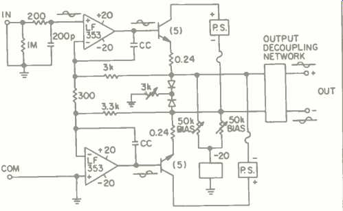
Fig. 1-Simplified schematic of one channel of the Sumo Model Nine
Measurements
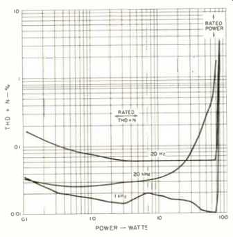
Fig. 2-Total harmonic distortion plus noise vs. power into 8 ohms at 20 Hz,
1 kHz, and 10 khz.
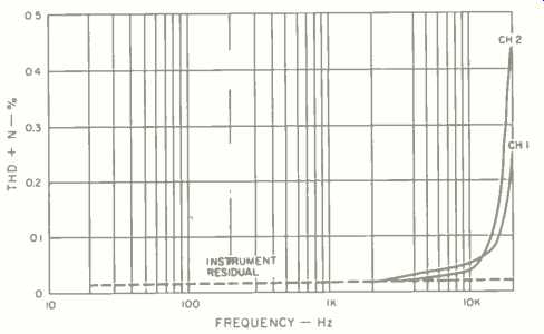
Fig. 3-Total harmonic distortion plus noise vs. frequency for 60 watts into
8 ohms.
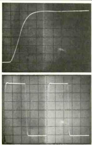
Fig. 4-Large-signal rise time measures 3.4 S. Scales: 2 uS/div., 10 V/div.
Fig. 5-Response to 10-kHz square wave input. Scales: 20 uS/div., 10 V/div.
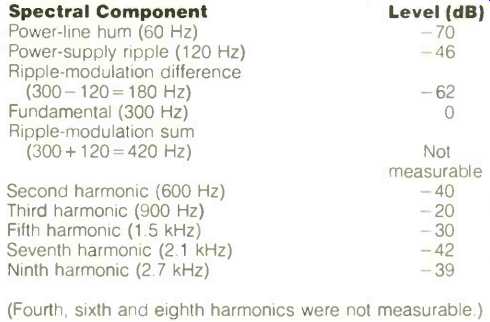
Table I-Clipping products with amp set for 10% THD overdrive with 300-Hz test
tone.
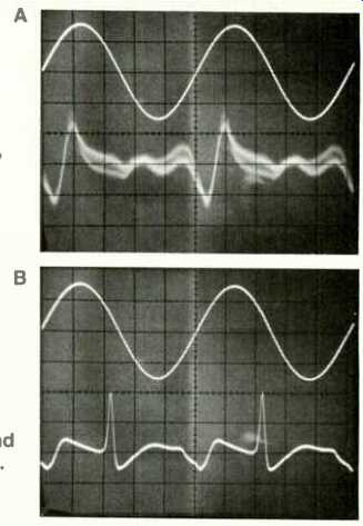
Fig.6 -- Distortion in Sumo Nine (A) looks much like crossover notch distortion
in a Class-AB amp (B), but at much lower level --0.04% vs. 0.25% THD. Both
sine waves are 15 W, 20 kHz. Scales: Horizontal, 10 µS/div. (all traces); vert.,
5 V/div. (both upper traces), approx. 5 mV'/div. (lower trace, A) and approx.
50 mV/div. (lower trace, B).
The Nine breezed through the FTC's one-hour, one-third power preconditioning at 8 and 4 ohms without "thermalling out," although the front panel and heat-sinks became fairly hot at 52° C and 83° C, respectively. To carry out power distortion tests, it was necessary to replace the 5-amp line fuse with an 8-amp fuse. The Nine then delivered 71 watts of continuous power per channel at 1 kHz for its rated distortion of 0.25% into 8-ohm resistive loads.
As shown in Fig. 2, the amplifier delivered 62 watts per channel at 20 kHz and 69 watts at 20 Hz into an 8-ohm load for its rated 0.25% distortion at its rated 60 watts. With a 4 ohm load, the amplifier delivered around 126 watts per channel at mid-frequencies, 120 watts at 20 Hz, but decreased to 76 watts at 20 kHz, for its rated 1.0% THD. Into 2 ohm loads, which the designer does not recommend, a visible distortion of the 1-kHz sine wave was seen above 17 watt (8.3 volts) power levels. Probably, the op-amp driver's current-output limits are the major performance drawback, producing an increase in distortion at 20 kHz. In some other audiophile amps, higher distortion results because of the use of low feedback around the output stage. In the Nine, output-stage feedback is used, but falls at 6 dB/octave. At 20 kHz the feedback is very low and, as a result, nonlinearities are higher. Figure 3 shows this rise in distortion at the upper frequency extreme.
The amplifier proved stable with both inductive and capacitive loads, with no reduction of maximum power before visible clipping when a 2-p.F capacitor was connected across the 8-ohm load in each channel. The 300-Hz clipping test showed excellent performance, with hum and side bands down more than 60 dB. In fact, the envelope of harmonics fell steadily as their frequency went up, which indicates a lack of sticking (an amplifier's tendency to continue clipping after the input signal has fallen back below the level which would normally make it clip). Table I shows that the Nine's clipping spectrum is superior to many other amps, and of particular note are the low levels of 60and 120-Hz hum, sum and difference products, and even-order harmonics (though there is some second), with no glitches, sticking or parasitics, as evidenced by the steadily falling distortion-spectrum envelope. While all distortion sounds bad, it is generally felt that small amounts of low-order odd harmonics sound reedy or suppressed, that low-order evens sound brassy, that high-order products of either type sound irritating and unmusical, and that modulation products sound dissonant, as they are not harmonically related.
Twin-tone or CCIF-IM measurements (mixed 19and 20-kHz signals) also showed products more than 60 dB down (i.e., below 0.1%), from 1 to 60 watts.
Figure 4 shows the large-signal rise-time, which was measured at 3.4 µS. The maximum slew rate is 15 volts per µS (symmetrical). The measured IHF slew factor, when rating the amp at 60 watts into 8 ohms, is 5.0. Figure 5 illustrates the Nine's square-wave response for a 10-kHz input signal driving the amplifier to just below clipping; there's only slight overshoot at the leading edge.
Signal-to-noise ratio, referred to 1-watt output, measured 91.75 dB (A weighted), somewhat poorer than claimed.
Input sensitivity for 70-watt output was 1.19 volts. A 0.132 volt input signal was required for 1-watt (2.28 volts) output.
Damping factor was 181 at 50 Hz, and exceeded 15 on wideband measures, about what Sumo claims. Power bandwidth extended from 3.2 Hz to 50 kHz.
On the 20-kHz sine-wave distortion measurement, as shown in Fig. 6A, a major distortion notch occurs at the positive-going zero crossing. Strangely enough, it has the visual appearance of crossover notch distortion, which is illustrated in a typical Class-AB amp in Fig. 6B, but it occurs only once per cycle. It is probably due to beta nonlinearities in the output transistors and the restricted current output capability in the op-amp driver.
Dynamic headroom, as specified by Sumo, showed a 0.0 dB reading at 4 and at 8 ohms. This is due to the regulated supply of the op-amp being fixed at 20 V.
Use and Listening Tests
The Sumo Nine was installed in Greenhill's home system and used to drive Dahlquist DO-10 and Snell Type A/11 electrodynamic loudspeakers. The amplifier was also auditioned in Clark's system, where it was inserted into one loop of an ABX RM-2 relay and compared to a Dyna 400 (an earlier Bongiorno design). Both amps were driving a low impedance, highly reactive speaker, consisting of an AR 1W woofer, a JBL 5-inch 2105 midrange, and an Electro voice EV-ST350 tweeter. Although rated at a nominal 4 ohms, the impedance dips to near 3 ohms each side of the bass resonance. Listening to the "Jungle Song" on Mark Levinson Presents (dbx record RTS-1), the Sumo amp played percussion passages smoothly and clipped unobtrusively. The gain-matched Dyna 400 clicked audibly on the same recording as its V-I limiting was triggered. The Sumo was clearly superior to this older, traditionally designed, but more powerful amplifier.
During listening, several operating characteristics of the Model 9 amplifier were noted. Hum and line frequency harmonics were audible at a low level until input leads were rerouted. The acoustical noise output of the fan was measured at 30 dBA at 1 meter when the amp was mounted on a shelf near a wall. Using a heavy-duty remote relay to turn the amplifier on, in order to place the amplifier away from the listening location, caused the Nine's 5-amp line fuse to occasionally blow from a turn-on surge.
This amplifier drove all three speaker systems with good overall definition and smooth, non-irritating clipping characteristics, though its power was inadequate for certain audiophile recordings of wide dynamic range, leading to frequent clipping.
The Sumo Model Nine amplifier is an intriguing design.
The symmetrical topology of its circuitry is appealing, and the design of its output stage does allow for Class-A operation in a cost-effective though limited manner. While the balanced outputs and frequently blown fuses on bench testing made measurements a challenge, the Nine functions smoothly when driving speakers in the listening room. Sumo's recommendation for the 5-amp line fuse will limit the continuous power of this amplifier to 23.3 watts into 8 ohms and 46.7 watts continuous into 4 ohms-more of a problem during bench testing than home listening.
Clearly, the transient behavior of , this amplifier, its clean clipping characteristics, its ability to drive reactive loads, and its wide power bandwidth make the Nine a good performer irrespective of the measurements.
--Laurence Greenhill and David Clark
( Audio magazine, Dec. 1983)
Also see:
Sumo Athena Preamp (Aug. 1989)
Spectrascan BPA-1 00B Power Amplifier (July 1984)
Streets Electronics Model 950 Power Amp (Jan. 1985)
= = = =