A FIXED STAIR
I get asked a lot of questions. The question that gets asked the most, and the one I find the hardest to answer, concerns the workings of digital oversampling filters. More and more CD players employ this method for output low-pass filtering, but I find that few people really understand what's going on. The situation hasn't been helped by the hocus-pocus advertising inflicted on consumers by some of the manufacturers trying to elevate their digital filter designs over those of the competition. Lackluster explanations in the audio press also haven't helped. I know I've tried, but I've never been satisfied that I've gotten the message across. This month (and next), let's delve into the topic of filtering, and specifically digital filtering. Although it's somewhat tricky, rest assured that when you understand digital filters, almost everything else in your CD player is cake.
Filtering is an unfortunate fact of life for digital audio systems. A recorder input anti-aliasing filter must precede the sampling circuit to uphold the Nyquist theorem's criterion for lossless sampling, i.e., the input signal must be band-limited to no more than half the sampling frequency. Similarly, a recorder or CD player must have an anti-imaging output filter following the D/A converter, again to filter out all frequencies above the half-sampling frequency, but its function differs. The analog signal at the output of the D/A converter is a pulse-amplitude-modulation waveform, easily spotted by its stair case appearance (Fig. 1). The sudden shifts in amplitude, which give it this shape, represent high-frequency components not present in the original analog waveform. These components include infinite series of multiples of the sampling frequency and of images of the original signal spectrum. Although above the highest audible frequencies, they are artifacts of sampling which must be removed to re-create the original, smooth waveform. The output filter is, in fact, sometimes referred to as a smoothing filter.
Sharp-eyed readers might question the need to worry about frequencies such as 88.2 or 176.4 kHz, since they lie so far above the limits of audibility.
Why waste money on such a filter when the ear itself is rather effective at filtering everything beyond 20 or 25 kHz? The original waveform is reproduced without filtering, but it is accompanied by image bands that could stress a CD player's or DAT recorder's output amplifier or cause intermodulation in downstream analog equipment through which the signal passes. For example, the high-frequency components might inter-modulate with the base-band frequencies to cause audible distortion or beat against an analog tape recorder's high-frequency bias signal to produce spurious tones. Filtering is mandated.
Thus, a low-pass filter must follow every audio digitization system. At first glance, this means an analog filter suit able for processing the analog signal as it leaves the digitization system. Engineers have been designing analog filters for a long time; there would seemingly be little trouble with this particular assignment. Ideally, we would like to attenuate all audio frequencies above the half-sampling frequency yet not affect the lower frequencies in the audio band. Moreover, we would like the transition from the unfiltered to the filtered frequencies to be very sharp.
This would let us make the usable band space as broad as possible to yield an extended and flat frequency response. An ideal filter would have a flat passband (the audio range which the filter passes), a steep or brick-wall filtering characteristic, and a stop-band (the frequencies which the filter eliminates) attenuated to below the system's quantization resolution. In addition to these criteria for frequency response, an ideal filter would not affect the phase of the signal or any other time-domain characteristic.
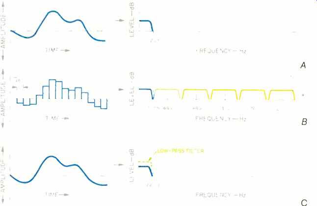
Fig. 1--In digital playback, a smooth waveform containing only audio-band
signals (A) is reconstructed by the D/A converter into a staircase shape
(B).
This contains the sampling frequency plus an infinite series of sampling-frequency multiples and images of the original signal's audio-band spectrum. Low-pass filtering smooths the waveform (C) and removes the images.
In practice, implementing such an ideal filter presents a number of engineering challenges: A brick-wall de sign means compromise in other parameters, such as flat pass-band and low phase distortion. To alleviate the problems inherent in a brick-wall response, we could design filters with more gradual cutoff; these, for example, would not exhibit phase nonlinearities. However, the frequency of the half-sampling point would have to be raised, to place it in a sufficiently attenuated part of the filter characteristic.
Therefore, a higher sampling frequency, much higher than that required for a sharp cutoff filter, would be needed to achieve the same flat frequency response. To limit the sampling rate and make full use of the band space below the half-sampling point, brick-wall filters at both input and output of the system are a necessity. Our problem is now stubbornly defined.
Basic filter elements of various types can be cascaded (repeated in series) to sharpen the cutoff. The greater the number of repeated stages, the steeper the filter-until the ideal filter frequency response is approximated. Un fortunately, as the cutoff steepens, the phase shift increases as well. Compact Disc players might require ninth-order filters; the cutoff would look like the North Rim of the Grand Canyon (that's good), but the phase shift might exceed 360° at 20 kHz (that's bad). Such a phase shift would introduce nonlinear time delay across the audio frequency band.
The resulting group delay, which measures the change of phase shift with respect to frequency, causes high frequencies to be delayed relative to lower frequencies. The delay increases toward the cutoff frequency of an analog filter, creating a kind of "time smear" in the signal. With an analog brick-wall filter, this frequency-dependent group delay at 20 kHz might be 100 uS relative to 0 Hz. Whether grossly audible or not, it is certainly measurable. Obviously, it is preferable to avoid any such group delays in the frequency response of a CD player.
Given the problems with analog filters, we might wonder, is there some way of interfacing digital storage with the analog world without using analog filters? The answer is yes and no.
When the output filter is placed after the D/A converter, it is necessarily an analog device. But there's an alternative: Filtering can be implemented in the digital domain before the D/A converter. Using digital filters, we can place the burden on the back of digital signal processing-a stronger and more versatile beast than analog circuitry. With clever manipulation of the numerical data itself, we can alleviate the need for an output brick-wall filter.
And yet, even then, we'll still need an analog filter, albeit a fairly harmless variety.
Next month, we'll see how digital filters work and what they and analog filters have in common. The delay until then is, as you'll see, appropriate.
(by KEN POHLMANN; adapted from Audio magazine, Dec. 1987)
= = = =