by Ken Kantor [Ken Kantor is president of Product Design and Evaluation Services, in San Francisco, and is co-founder of speaker manufacturer Now Hear This.]
In Part I of this article, with the help of a personal computer, we walked through the design of a two-way, 6 ½ inch loudspeaker system. We selected appropriate drivers, determined cabinet volume, and developed and refined a crossover network. Now we are ready to discuss the construction of our loudspeaker system. This won't be a step-by-step instruction manual, as you would find in a kit. Rather, it is assumed that the reader has the skill to work from sketches, so we will therefore concentrate on the general issues involved in loudspeaker construction (cabinet shape, driver placement. etc.) along with some specific construction guidelines.
Just as our previous selection of drivers and crossover topology avoided esoteric approaches in favor of quality elements and proven design techniques, so too our cabinet design will follow the same logic. Taking this course will result in a loudspeaker with very good performance. The inspired reader is encouraged to experiment with alternative materials, shapes, and construction techniques for the cabinet enclosure.
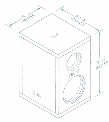
Fig. 8--How the finished enclosure fits together.
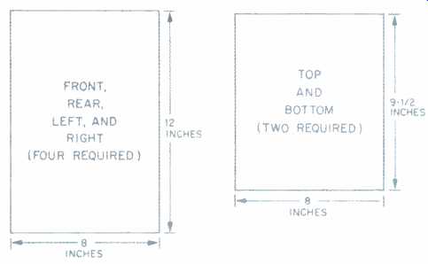
Fig. 9-- Dimensions of the enclosure's individual parts. Note that four
8 x 12-inch and two 8 x 9 1/2-inch pieces are required for each loudspeaker
Box Dimensions
As shown in Table VII, the first step of our construction will be to translate our calculated enclosure volume into working cabinet dimensions. Since we are leaving the realm of engineering to enter that of carpentry, we probably should make a transition from meters to inches. Doing this, our target enclosure volume of 10 liters translates into 610 cubic inches, which is equivalent to a cube of about 8.5 inches per side. In loudspeaker terms, a cubic enclosure is not really a very good idea, for two reasons. First, the more similar the three internal cabinet dimensions are , the more standing waves will tend to build up and reinforce one another.
This leads to irregular frequency response in the upper bass and midrange, with resulting coloration, particularly of vocals. The second problem is finding room for the tweeter on the same surface as the woofer.
Figure 8 shows an assembly that will allow the entire cabinet to be constructed from stock boards that are 3/4 inch thick and 8 inches wide. The stock material can be cut into six lengths to form the six sides of our enclosure. This technique will maximize the use of pre cut edges, thus making it easier to achieve tight, clean joints. The 8-inch boards result in an internal cross-sectional area of 52 square inches. Some quick calculating indicates that a height of 11 3/4 inches will provide a volume within 1% of our target of 610 cubic inches. Increasing this to 12 inches gives us 624 cubic inches, which is just about right to account for the space taken up by the rear section of the woofer. The dimensions of the six boards required for each speaker are given in Fig. 9.
Medium-density fiberboard (MDF) makes an excellent material for the construction of smaller loudspeakers.
"Medium density" refers to the ratio of fibers to adhesive in the composite; the actual stuff is much denser and more vibration-resistant than wood. A thickness of 3/4 of an inch is recommended, as this will provide adequate structural rigidity without the use of any bracing.
Particleboard will also provide enough strength, but it is harder to obtain a clean surface appearance, especially at the edges of the boards. If care is taken to assure good corner joints, a speaker this size should be very solid.
Parts and Parcels
A quick and convenient way to obtain material for our speaker box is to buy prefabricated shelves from a hard ware store. These are readily available in the 3/4 x 8-inch size, in several lengths, and can be purchased with a variety of relatively attractive finishes.
Two speaker cabinets require a total of 134 linear inches of material, but allow extra for cutting losses and be sure to consider how the required cuts fit into the particular lengths you buy. For example, if 36-inch prefab shelves are purchased, four should suffice for each pair of speakers built.
Table VIII lists the major parts required to build a single speaker. In many cases, substitutions or modifications are acceptable; these changes are noted in the text where appropriate. For this reason, it is a good idea to read carefully through the sections de scribing various assembly tasks. Plan out how you intend to approach the construction, and alter the parts list as you wish. Almost any hardware store should have the materials required for the box assembly. Finding crossover parts, however, will be more difficult.
Typical electronics supply stores do not carry the type of capacitors or inductors necessary to build speaker crossovers. A list of companies that specialize in the sale of speaker parts can be found in Table IX. All of these firms should be able to provide the crossover parts discussed here, and most will be happy to send a catalog of their offerings. Often, local audio shops, particularly those doing service work, sell inductors, capacitors, resistors, and even terminal cups. These may not be on display, so it pays to ask. Radio Shack sells a variety of speaker terminals and capacitors. Be sure that the terminal cup you get is specifically designed for speaker use, for terminals used on amplifiers are rarely airtight. Old Colony Sound Lab has arranged to provide Audio readers with the Tonegen 16K65 woofer and 94C70 tweeter. This company is, in fact, the only source of these driver units in the U.S. (see Table IX for terms of sale).

Fig. 10 Cutout details for front and rear boards.
If facilities for making the recesses shown are not available, false fronts incorporating the recesses can be glued on; see text.
===================
Table VII-Steps in the construction process.
1) Determine enclosure's internal dimensions
2) Purchase construction parts and materials
3) Cut six panels
4) Machine driver and terminal cutouts
5) Assemble enclosure
6) Assemble crossover and terminals into enclosure
7) Add polyester fiber material
8) Assemble drivers into enclosure
9) Test for air leaks and driver polarity
10) Hook up to stereo
11) Impress friends
12) Browbeat enemies
===================
Table VIII-Major parts required (per speaker).
Drivers:
Woofer--Tonegen 16K65.
Tweeter--Tonegen 94C70.
Crossover Terminal cup--Two-connector.
Capacitor--2.2 uF, 100 V, 10% non-polar electrolytic.
Inductor--0.6 mH, air core, 18 gauge (two needed).
Resistor--10 ohms, 15 watts, 5%.
Perfboard--3 x 5 inches.
Wire--18 gauge; approximately 40 inches red, 40 inches black.
Enclosure Construction:
Fiberboard--3/4 x 8 x 67 inches.
Mounting screws--3/4-inch pan head #6 (11 needed).
Foam weatherstrip tape—1/8-inch thick x ¼-inch wide; 48 inches needed.
Glue, screws, caulking--As required.
Polyester fiber-2 ounces.
====================
Cutting and Drilling
First off, cut and drill with care, especially when using power tools. Cut the lengths of board according to the dimensions given in Fig. 9. Try to get clean edges on the pieces. Not only will your speakers look better, it will be easier to get a good airtight seal from the finished enclosure. A table saw is recommended because of the straight edges and accurate right angles it provides. If you do not have access to one, a local lumberyard can cut your stock or even sell you cut pieces. Just impress upon them the need for accuracy. If you are good with a circular saw, or really good with a handsaw, best of luck. If you don't mind lots of caulking, you can even use a jigsaw or a saber saw.
Before the boards are assembled, holes must be cut in two of the 8 x 12-inch sheets for the drivers and terminals. These holes are shown in Fig. 10.
The terminal cutout dimensions given are typical for molded plastic cups which contain spring clips or binding posts. Of course, you should adjust the size and shape of these holes for the particular terminals you choose. It is best to leave the driver positions as indicated. The relative spacing between woofer and tweeter has a great influence on crossover design, since it affects how the sound waves add up in the transition-frequency region. In general, closer spacing is better, as long as enough material remains for solid support. The driver and terminal openings can be cut successfully with a hand-held jigsaw; many of these saws accept an inexpensive attachment for making clean circles. If yours does not, just draw a line in pencil and follow it by eye. Be sure to use the inner diameters shown in Fig. 10 when cutting holes for the two drivers. The outer circles, shown by a dotted line, are for recessing the drivers into the front pan el. These cutouts don't need to be super accurate or neat, just reasonably close. The little notch for the tweeter terminals should be filed away after the circle is cut.
The next step is probably the hardest one in this entire construction project. The job is to provide a routed band around the driver holes so that the drivers may be recessed back.
Flush-mounting the drivers, particularly the tweeter, provides a noticeably smoother response. Diffraction effects can cause up to 3 dB of boost at the lower part of the tweeter's range if the tweeter protrudes from the front panel.
Recessing the woofer is less important, but it will have some effect due to the reflection and diffraction of tweeter output. There isn't an easy way to ma chine these recesses with hand tools; it might be possible, but it probably would not be fun. The task would be simple for a wood shop worker with a router, however, and can be accomplished on a home drill press if care is taken.
Because routing is difficult, an alternative approach may be attractive. Using dense (not corrugated) 3/16-inch thick cardboard or poster board, cut a template and glue it onto the speaker front. The template should be 13 1/2 x 8 inches and should have cutout hole diameters of 3 3/4 and 6 5/8 inches. Attachment of this piece should be delayed until after the box is assembled.
If the cardboard is cut accurately and then painted, it should be undetectable--in fact, it will help hide the joint line formed by the top and bottom pieces, resulting in a nicer front view. If glued firmly, dense cardboard, poster board, or any other solid, smooth-surfaced material will serve our acoustic needs just fine.
Because of the wide variety of construction approaches possible, many of the final box assembly decisions are left to the reader. The important thing is to get a strong, airtight seal at every joint. (We will test the integrity of the seal after the drivers are installed.) The simplest technique would be to glue together the four sides with wood glue, securing them immediately with small nails. After the glue dries, the top and bottom can be glued and nailed on in the same way. Later, through the woofer hole, all the internal joints can be caulked with silicone sealer or hot-melt glue. Glue- and caulk-only methods are certainly possible. The result will be a nice outer appearance, but this approach does require clamping of some sort.
==============
Table IX--Parts sources.
Just Speakers, 3170 23rd St., San Francisco, Cal. 94110; (415) 641-9228.
Madisound Speaker Components, 8608 University Green, Box 4283, Madison, Wisc. 53711; (608) 831 3433.
Old Colony Sound Lab, P.O. Box 243, Peterborough, N.H. 03458; (603) 924-6371.
Drivers only: $127 for pair of woofers and pair of tweeters; price includes ship ping in U.S. Defective units will be replaced at no charge if they are returned with freight prepaid. Units damaged accidentally or because of abuse will not be replaced or repaired.
Option Audio, 32 Terrapin Lane, Mercerville, N.J. 08619; (609) 890-0520. Unfinished medium-density fiber board (MDF) front panels, $40 per pair, including ship ping. Entire completed enclosure also available; prices vary with materials and finishes specified.
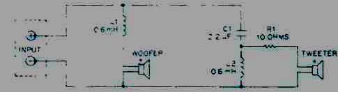
Fig. 11--Diagram of speaker and crossover wiring. See the Parts List (Table
VIII) for details on components.
==============
Soldering
The final crossover values are shown in Fig. 11. Even those not familiar with reading circuit diagrams should be able to handle this one. Connection polarity is not important on the resistor, capacitor, or inductors; it is important on the terminals and drivers, however, so observe the plus and minus signs here. The positive driver terminals are marked in red. All connections should be soldered using electronics-grade rosin-core solder. Do not use the plumbing or acid-core variety.
Most electronics supply stores should have the 2.2-p F capacitor value. Incidentally, the crossover response has been specifically designed for the characteristics of a bipolar electrolytic capacitor. You cannot simply replace this part with mylar or polypropylene types. Their lower internal resistance will result in several dB of excessive high-frequency energy. If you are inclined to make this substitution, add a 3.3-ohm, 10-watt resistor in series with the 10-ohm resistor, to re store proper tonal balance.
The circuit can be built free-form and then glued, piece by piece, to the in side bottom of the speaker box. Hot-melt glue works great for this, which is why so many manufacturers use it. The network may also be assembled onto a piece of perfboard, which in turn is glued or screwed down. There are three things to remember when laying out the crossover parts. Keep the two coils at least 2 inches apart; otherwise, they can affect one another electrically. Further, the resistor gets moderately hot under high-power conditions; don't let it touch other components. And finally, place the crossover circuit far enough back in the box so that it won't interfere with the woofer mounting.
It is a good idea to cut and attach leads for the drivers and terminals be fore the crossover goes into the box.
Strip and solder coat the loose ends of the wires. Use red wire for positive leads, black for negative ones, and be sure to label each wire as to its destination. This will make things much easier when it's time to insert the drivers. A length of 12 inches is recommended for the woofer leads, 16 inches for the tweeter leads, and 10 inches for the terminal leads.
Final Assembly
Once all the glue is completely dry, we can start final assembly. To get a truly airtight seal, it is necessary to have a soft gasket between the fiber board and the drivers and terminal cup. Adhesive-foam weatherstrip tape can be used for this. Buy the softest 1/8 x 1/4-inch material you can find. Lay the drivers face down on a table and wipe off their mounting flanges with a paper towel or clean cloth to remove dirt and oil. Now apply the foam tape completely around the driver flange, just to the point of overlap. On the woofer, the tape should lie toward the inner edge of the flange; on the tweeter, put the tape toward the outer edge.
You should also apply tape to the mounting flange of the crossover cup.
If any screw holes get covered, just pierce the tape with a pin. There is no need to clear the hole.
Now it's time to close things up.
Place the terminal cup in the back hole, and mark the screw locations.
Remove the cup and drill or punch small pilot holes to facilitate screw insertion. Find the leads for the terminals and pull them through the hole. With the cabinet resting on its front side, the terminal leads can be soldered to the terminals (observing polarity), and the cup can be screwed down to the cabinet. If there are no clear polarity markings on the terminals, use the red connector for positive.
Turning the cabinet over, pull the woofer and tweeter leads through their respective front-panel cutouts. It's a good idea to tape the leads to the cabinet with masking tape to avoid losing them when inserting the polyester fiber. Polyester can be obtained at a store that sells sewing materials or fabric; discount departments stores generally carry it too, for making or repairing pillows and blankets. If you have a choice, select the material which has the softest feel.
There are no formulas for calculating the exact amount of fiber to use in a speaker. With the mixed dimensional units that indicate a good, scientific rule-of-thumb, most designers try between 1 and 1.5 ounces per 5 liters of enclosure volume. We'll use 2 ounces.
The fiber can be weighed in a light plastic bag on a postage scale. Start with too much, and remove a little at a time. Throw away the torn bits, since small, unattached pieces could conceivably foul up a woofer. The fiber should be spread evenly throughout the box and should flow around and behind the wires.
Mark the driver screw holes as you did for the terminal cup. It will be easier to remove the drivers if you apply small tags of tape before dropping them into their openings. Resting the drivers on the cabinet, carefully solder on their leads (again observing polarity). Don't overheat the driver terminals as this may damage them. Lastly, screw the drivers securely into the box, tucking the leads back into the fiber. If you opted for a cardboard facia, glue it onto the enclosure now.
Basic Tests
There are two very basic tests to perform before connecting our completed speakers to an amplifier: Air seal and woofer polarity. Air seal is pretty easy. Gently push the woofer cone back into the cabinet until increased resistance is felt. Take care to push at several points at once, and don't press on the dust cap. Hold the cone down for about 5 seconds and then release it, watching closely. The cone should return slowly and evenly to its normal position, taking a good 1 or 2 seconds to do so. A more rapid return indicates one or more air leaks, in which case all joints and seals are suspect. Often, if a hissing sound is heard when pushing on the woofer, this is a clue to a leak. The flickering of a match flame can also help you locate a leak; to create the necessary wind, either push on the woofer or play music at a moderate level with your bass control all the way up. If you suspect a problem, be sure to check out the areas around the drivers and the terminal cup, as well as all the joined edges.
Caulk will usually fix a leaky edge. A bad driver seal can often be cured by simply removing and reseating the unit. Stubborn cases might require a second layer of foam tape.
The second test confirms proper woofer polarity. Use two lengths of wire to connect a 9-V transistor-radio battery directly to the speaker terminals for a few seconds. The positive battery terminal (the smaller one) must be connected to the positive speaker input (red). Proper polarity is indicated by an outward motion of the woofer. When the battery is disconnected, the woofer should slowly return to rest, which serves as a last check for air leaks.
Chances are very good that your system will work perfectly as soon as it is finished. All the component parts are extremely reliable, and there aren't many glitches that won't surface during our two simple tests. Almost all of your listening should be for pure enjoyment, not for analysis. However, it is a good idea to listen for a few potential problems that can arise, just as a pre caution. I won't say too much about listening tests; Audio readers probably do them a lot. Besides, speaker builders are like new parents: They think their creation is far and away the best-at least for the very first part of its new life. I've never been anything but overjoyed when listening to one-of my own designs . . . until the morning after.
This design has been balanced for mid-shelf placement. Corner or floor placement will increase deep bass output. Likewise, a more open placement-say, on stands moved out from the rear wall-will result in a lighter overall balance. Overly bad imaging and/or a suck-out in the midrange indicate that one or both tweeters are out of phase. No highs mean a tweeter problem, no lows a woofer problem.
Naming the Baby
At first, I wasn't going to name this loudspeaker, which has served to illustrate, among other things, the role of personal computers in speaker de sign. However, in the course of reading up on other published designs, I realized that naming the new baby is practically obligatory. Since I dislike futuristic, technical names for audio products, I hoped to find something warm and human.
After considerable reflection, I decided to dedicate my new design to the acclaimed editor of Audio magazine who, in truth, gave me my first big break in the writing business several years ago. I refer, of course, to Eugene Pitts III. Upon reflection, however, I realized that this name was too long for a 6 1/2-inch loudspeaker. So for the sake of simplicity, I'll call it "The Pitts."
(adapted from Audio magazine, Dec. 1988)
Also see: Speakers by Design by Ken Kantor -- Part 1 (Nov. 1988)
= = = =